


mboxler
-
Posts
574 -
Joined
-
Last visited
Content Type
Forums
Events
Gallery
Everything posted by mboxler
-
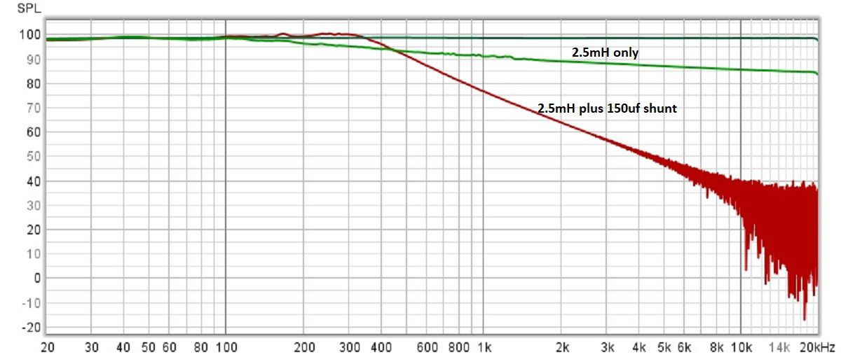
The more I learn about crossovers, the more confused I get. When one refers to a crossover point, is one referring to voltage or SPL? Since a crossover can only control voltage, I took a wild guess. I tested the voltage across a Khorn K-33E with a 150uf shunt, and it came pretty close to a second order, 400hz filter. The filter had to be underdamped to get to that point, hence the slight bump in voltage before it drops. Not sure how it would blend with the first order high pass to the squawker, though. Mike

-
I think it's actually more interesting than that. If the tweeter filter is connected before the 13uf capacitor, the load on the 13uf capacitor stays consistent, and the voltage drop across the capacitor will approach zero as frequency increases. Taps 0-5 will eventually get the full voltage. If the tweeter filter is connected to tap 5, the load on the 13uf capacitor becomes a bell curve, peaking out around 500-700hz. After that, the load drops quickly. At the rate the load is dropping, the voltage drop across the 13uf capacitor actually levels off, even though the frequency is increasing. That extra voltage drop never gets to taps 0-5. I'm guessing that's why Klipsch changed autoformers when they went with the elliptical tweeter filter. Since that filter is attached before the 13uf capacitor, it doesn't mess with the load on the capacitor, and more autoformer attenuation was needed.
-
Sounds like you are trying to turn the tweeter filter to a 3rd Order Butterworth, like the Universal's filter? Then yes, the second capacitor is 3 times larger than the first. If you want to get the the Universal's 6000hz crossover point, simply changing the second capacitor in an AA to 6uf won't work. An ideal 6000hz 3rd Order Butterworth filter into an 8 ohm load would be 2.2uf, 160uh, and 6.6uf values. Since the first 2uf capacitor on the AA is in series with the 13uf capacitor, it effectively becomes a 1.75uf cap. A 1.75uf, 245uh, 6uf combination ends up crossing around 8800hz. In order to get a 6000hz filter, you would need to replace the first cap with a 2.7uf, replace the inductor with a 160uh, and replace the third cap with a 6.6uf. A 2.7uf cap in series with a 13uf cap is around 2.2uf. Keep in mind, the tweeter filter attached to tap 5 in a stock AA drops the voltage to the squawker (tap 3) by an extra 1.5db or so. Looks like changing the tweeter filter to the 2.7uf, 160uh, 6.6uf values will drop it another .5db. I think I got my simulations correct. Mike
-
I was planning on connecting the common strap (and tap C) to squawker "+" and the 3619-ET output tap to squawker "-". Looking at Al's website picture of his Universal Economy, it sure looks like the 3619-ET tap "6" is connected to squawker "+". I assume tap C is connected to the common side of the "swamping" resistor and the common wire strap is connected to squawker "-". The picture is at a bad angle so I guess I'm seeing it wrong.
-
I've read quite a few threads about this filter. Here's my uneducated take on it... I believe this is a three pole Chebyshev "Constant K" filter combined with a null pole. As I understand it, "Constant K" implies that the filter is designed for a circuit with equal source and load impedances. That's why the two series capacitors are equal. When this filter is used with a source impedance much lower than the load impedance, you get the familiar Type AA tweeter transfer function. I found this calculator which works great. Took a lot of trial and error to make it work. Someone smarter than me should be able to explain why it works. https://rf-tools.com/lc-filter/ For a high pass filter, I multiply the desired crossover frequency (-6db point) by 1.6. For a 6000hz cross, that's 9600hz. The screenshot shows the data entered. Note that the input impedance and output impedance are both set to 8 ohms (Constant K?). The Klipsch elliptical filter closely matches the computed component values. The 125uh inductor appears lower the crossover by around 300hz. The values for the null pole are pretty straight forward. Use the same value capacitor in series with an inductor that's 4 times the value of the Chebyshev shunt inductor. That would be a 2uf capacitor in series with a 460uh inductor, or in Klipsch's case, a 500uh inductor. The second screenshot shows both the Chebyshev filter alone and the Chebyshev filter with the null. I used the calculator's values for the simulation. The same calculator can be used to design a low pass filter as well. Instead, though, you divide the desired crossover frequency by 1.6. For the null, use the Chebyshev calculated inductor value in series with a capacitor that's 25% of the Chebyshev shunt capacitor. Again, I'm no EE. Mike
-
Now I'm confused. As I understand it, the earlier Universal's with the 3619 left both squawker outputs floating...neither "+" or "-" were directly tied to common. This allowed the squawker output's polarity to be reversed by, say, connecting tap X to output "+" and tap 4 to output tap "-". It looks to me that the newer Universal with the 3619-ET has tap C connected to the squawker out "-", which is also connected to the common wire. Any one of the output taps 3 thru 18 is connected to squawker out "+". It seems to me that the polarity to the squawker is no longer reversed??? Am I seeing this wrong or was this also a design change with the newer Universal's? I assume the lowpass to the squawker is still second order. Mike
-
I think it's the other way around. A 2.5mh inductor is 4 ohms at 250hz, 8 ohms at 500hz, and 11 ohms at 700hz. I believe the Type E (2.5mh inductor) was designed for an 11 ohm woofer impedance (700hz).
-
K77 measuring 10db hotter than CT-125. Is that right?
mboxler replied to mboxler's topic in Technical/Restorations
One of them is 6.21 ohms, the other 6.23 ohms. -
I gotta be doing something wrong, but can't figure out what. I'm testing some crossovers I just built for my Khorns. They attach to ALK ES5800's for the squawker to tweeter cross, which has been a K55M and a CT-125. The CT-125 didn't seem to measure well using REW, so I thought I'd see how the original K77 looked. This is a direct swap, yet the K77 measures almost 10db higher than the CT-125. Is there really a 10db difference between the two? I was under the impression their sensitivities were pretty close. Graph is with the squawker on the -6db tap and tweeter on the -0db tap. Thanks, Mike
-
This was done so one could use an 8 or 16 ohm midrange and the load on the second order low pass filter will still be close to 8 ohms (due to the swamping resistor). As long as you don't plan on switching back and forth between 8 and 16 ohm drivers that "Universal" feature isn't as important, in my humble opinion. Not sure how many 8 ohm squawkers are in use. Mike
-
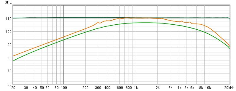
Has anyone experimented with placing the low pass to the squawker after the autoformer? It would seem that doing so would allow one to attach the tweeter circuit to any output tap for attenuation, if needed. Granted, the inductor and capacitor values would need to be changed, but this eliminates the need for a tweeter attenuator. For fun I whipped up a simple circuit. It consists of a 24uf capacitor in series with a .75mh inductor. I placed a 1.3uf capacitor across the squawker output terminals. On the following graph, the green plot is the voltage across a K55M using the ALK Universal (taps x - 4). The orange plot is the test circuit. Other than the voltage drop caused by the Universal's autoformer, the plots are pretty close. I'm sure with some component tweaking they could be even closer. Just a thought. Mike
-
Anyone using LTspice to simulate and REW to test crossovers?
mboxler replied to mboxler's topic in Technical/Restorations
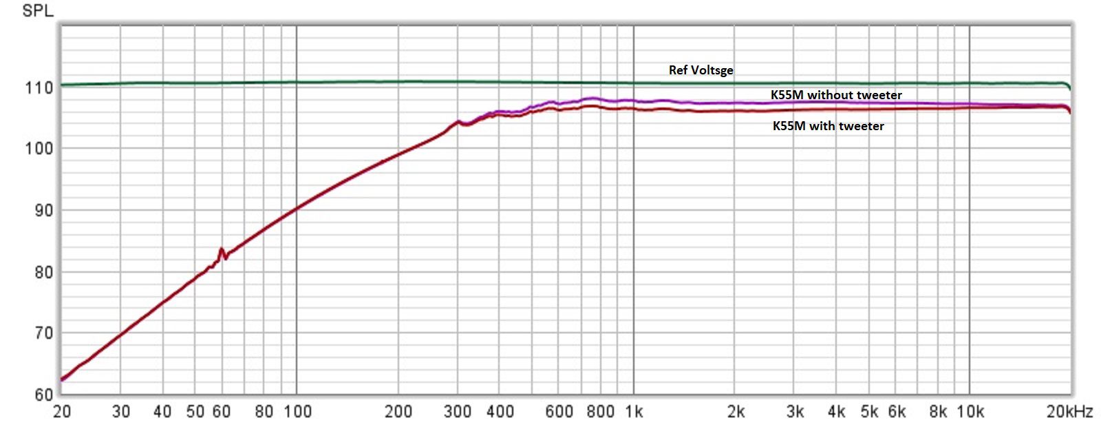
During my crossover tests, I noticed something interesting. Connecting a tweeter circuit to tap 5 of the autoformer attenuates the squawker by another 1.5db or so. I'm sure this is not news to some of you, but to others like me... I don't have a Type A crossover, so I simulated one. I don't have a 13uf capacitor, but was able to parallel a couple to reach 12.7uf...close enough. This was connected to tap 5 of a T2A, and I connected tap 4 to the K55M in my Khorn. The purple plot shows the voltage across the K55M. It's down around 3db. I then connected the tweeter circuit to tap 5 and noticed the extra 1.5db drop across the K55M (brown plot). That attenuation is pretty flat throughout the useful frequency response of the K55M. Was the reason Klipsch used a T4A due to the fact that the AK-3 tweeter filter is not connected to tap 5?
-
Are Shunt Capacitors in the Signal Path?
mboxler replied to mboxler's topic in Technical/Restorations
Nice! It's interesting how many ways one can describe what is happening. My description, although similar, works for me... A capacitor blocks everything, or to put it another way, electrons do not flow through a capacitor. When a capacitor is in a series circuit, current only flows when there is a change in voltage. The slower the voltage change, the less current will flow (think low frequency audio). The faster the voltage change, the more current will flow (think high frequency audio). -
Are Shunt Capacitors in the Signal Path?
mboxler replied to mboxler's topic in Technical/Restorations
I believe so. When I was testing I2S output pins on an ESP32 project, I had no scope. I knew, however, that the master clock pin should be varying from 0V to +3.3V at a 50% duty cycle. I set my DMM to DC and measured between ground and the MCLK pin and measured 1.65V DC, so at least I knew I had a clock. I'm pretty sure the measurement didn't work when I set the DMM to AC. -
Are Shunt Capacitors in the Signal Path?
mboxler replied to mboxler's topic in Technical/Restorations
I agree. However, if you change the signal to switch from +0V to +2V, is it still AC? I think, with a series capacitor, current will flow the exact same way in both circuits??? -
Are Shunt Capacitors in the Signal Path?
mboxler replied to mboxler's topic in Technical/Restorations
I guess in my simple mind it can also convert varying voltage DC into alternating current. Simpler yet, the capacitor removes the DC offset, if any. Perhaps this graph will explain my fuzzy thinking... The voltage source is a 100hz sine wave, 20 volts peak-to-peak, with a 10 volt DC offset (green plot). A series capacitor of 13uf. An 8 ohm resistor (red plot). As I see it, if the capacitor was not in the circuit, current would only flow in one direction, and that current would vary from 0 to 2.5 amps. The current through the resistor is not alternating(?). With the capacitor, the now current flows in both directions through the resistor...AC. This happens because the capacitor's plates are continuously charging and discharging through the resistor and voltage source. As everyone can tell, I'm no EE, so thanks for your patience.
-
Wouldn't the main advantage of a single resistor be the ability to use smaller value capacitors? A single series resistor equal to the impedance of the driver (-6db) would require a capacitor half the value vs a -6db lpad.
-
Are Shunt Capacitors in the Signal Path?
mboxler replied to mboxler's topic in Technical/Restorations
Thanks to all, and yes, It's great that Ohm's Law applies to reactive impedance as well as resistance. Using the components from my earlier post, I plotted the following... Top graph shows current. Red is resistor, blue is capacitor, and pink is the sum of these two components. Green is the current through the inductor. Since the inductor current is equal to the sum of the parallel components, the current through the parallel components is hidden (equal). Bottom graph shows reactive impedance. Green is the impedance of the entire circuit, and red is the impedance of the parallel resistor/capacitor. I realize it's hard to see, but they closely match the figures in my earlier post. Getting back to the original question, perhaps it's up to the speaker builder to determine the quality of the shunt capacitor. Or the shunt inductor for that matter. Mike
-
Are Shunt Capacitors in the Signal Path?
mboxler replied to mboxler's topic in Technical/Restorations
Thanks! Your words are much clearer than mine. I like your use of the phrase "alternating polarities". I guess in my simple mind the capacitor "creates" AC in the circuit as opposed to "passes" AC. Perhaps that thought process only works for me. -
Are Shunt Capacitors in the Signal Path?
mboxler replied to mboxler's topic in Technical/Restorations
Actually that's the video that I came across a couple of years ago. Really helped me understand reactive components. -
Are Shunt Capacitors in the Signal Path?
mboxler replied to mboxler's topic in Technical/Restorations
I agree, but it's not AC either. My point is that the phrase "blocks DC and let's AC pass" may be misleading to others interested in how capacitors work. -
Are Shunt Capacitors in the Signal Path?
mboxler replied to mboxler's topic in Technical/Restorations
Agree, but as I understand it no current can pass through a capacitor. As I stated above, no current can pass through a capacitor. Since a capacitor is an open circuit, current can only flow from one plate to the other via the circuit itself. Current only flows when there is a change in voltage, and the quicker the voltage change, the greater the current flow. This current flow is instantaneous, and is 90° ahead of the voltage change. An example that I would be afraid to try would be a capacitor is series with a driver. Hook this circuit to a 12 volt battery. The instant the battery is connected, current will flow through the circuit, including the driver. The current flow will decrease until the voltage across the capacitor is 12 volts, then will stop. I guess I wouldn't call this blocking DC. Again, this is how I understand it. Mike -
Are Shunt Capacitors in the Signal Path?
mboxler replied to mboxler's topic in Technical/Restorations
I find these explanations of current flow misleading, or I don't understand how capacitors work. Current cannot pass through a capacitor...it's an open circuit. Current (or charge) is stored on the capacitor plates, therefore the current can only flow two ways. From the "+" plate of the capacitor, through the inductor, through the amp, to the "-" plate of the capacitor. or From the "-" plate of the capacitor, through the amp, through the inductor, to the "+" plate of the capacitor. The capacitor is storing current that would otherwise pass through the woofer voice coil. It's not diverting that current back to the amp. Am I correct? -
Are Shunt Capacitors in the Signal Path?
mboxler replied to mboxler's topic in Technical/Restorations
Are you using the component values I stated above to get to these current levels? I seem to be coming up with something different. -
Are Shunt Capacitors in the Signal Path?
mboxler replied to mboxler's topic in Technical/Restorations
Is the choice between an electrolytic and a film capacitor based more on the "life" expectancy of the caps rather than the "quality" of the attenuated voltage across the driver?


.png.99a2ea6aae624b419a92fed51e596067.png)
.png.7ee1bea887eb131919e0f8c0936fa580.png)

.png.198741ccc4c8e885bdecb48ee82cc982.png)
.png.d5cd493a82e638a6eee09f5f9f27013f.png)