Langston
-
Posts
148 -
Joined
-
Last visited
Content Type
Forums
Events
Gallery
Everything posted by Langston
-
 Good question. Even the excellent link provided by the cool Frenchman with a taste for American cars is 1kHz oriented. I'll fix that and start another thread for it. : )
 -
I really like John Siau's audio philosophy, so when the Benchmark amp came out, it wasn't a question of whether to buy it, but how to get him to sign it! : ) The truth is I haven't had efficient enough loudspeakers to be able to use the amp enough to really get to know it, so I use it mainly to measure stuff. I love the fact that it has clip LED's! Like most amps these days, it'll throttle itself to prevent more than about 1% THD when overdriven, but I hate the idea not knowing when the amp is beginning to act like a compressor/limiter. I also love heavy symphonic music at live levels (OK, maybe a bit too live) and these '74 Klipschorns I've been working on recently probably won't take the AHB2 amp out of idle. With the Klipschorn, the high power portions of my inductor testing are silly, but I wanted to learn. I've actually never heard Klipschorns in my life, but I'm getting close - a couple of days from now and I'll find out what all the fuss is about. : ) On the 1kHz testing - I'm sure you're referring to the LCR meter results. I also looked at 100Hz, 120Hz, 10kHz and 100kHz, but I didn't think that was very enlightening. Everybody specs them at 1kHz - but I'm new at these things - let me know if you'd like to see the other frequencies for mH and Q. Another thing is that I've studied Q and know what it means and even how to calculate it without an LCR meter, but I still don't see how it applies in passive loudspeaker crossover applications. Please clue me in - I'd love to learn. Complex transfer function measurements agree with LTSpice simulations (of perfect inductors) at these "low" audio frequencies without the need to know anything other than mH and DCR. Above audio frequencies, I see why Q is a big deal. Thanks!

-
Heil Air motion transformer for Cornwalls
Langston replied to jwgorman's topic in Technical/Restorations
Thanks Mike! I just learned something new. : ) -
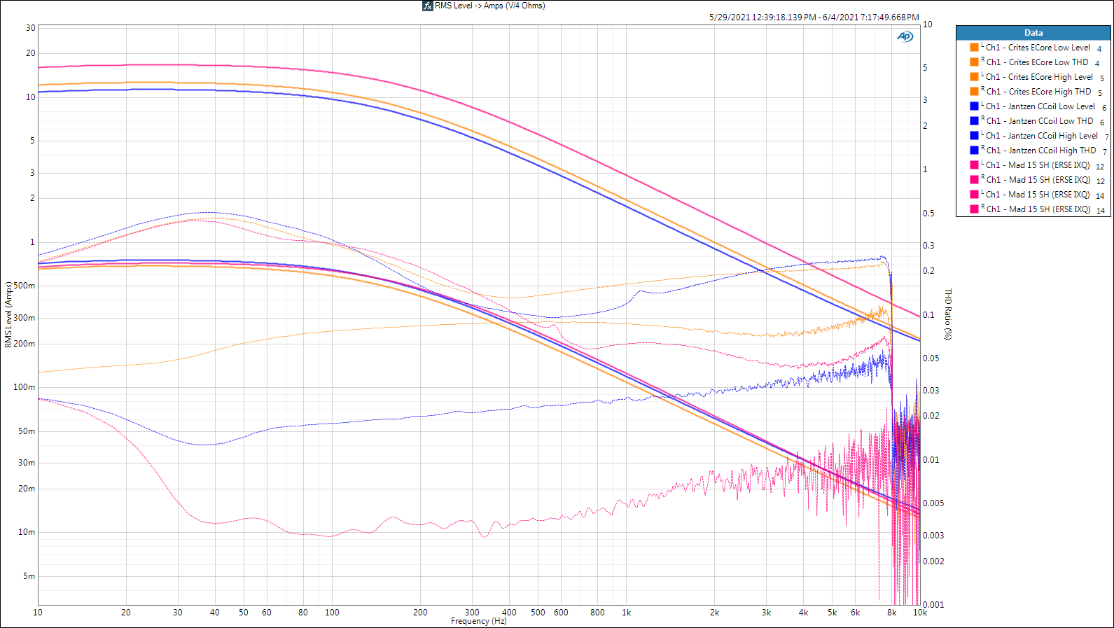
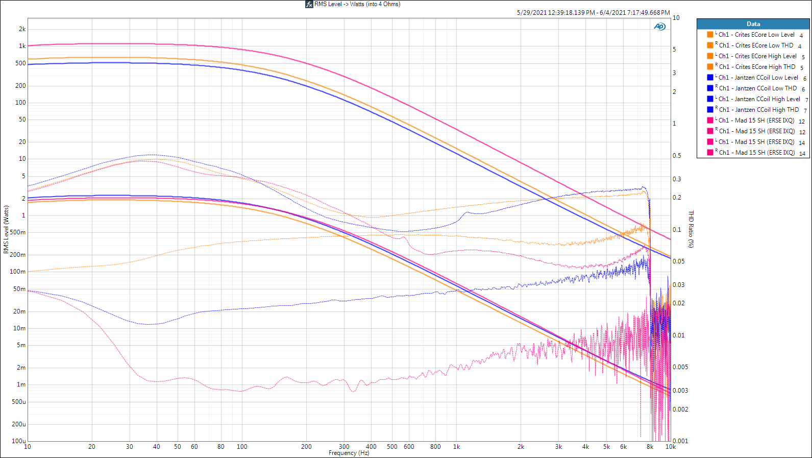
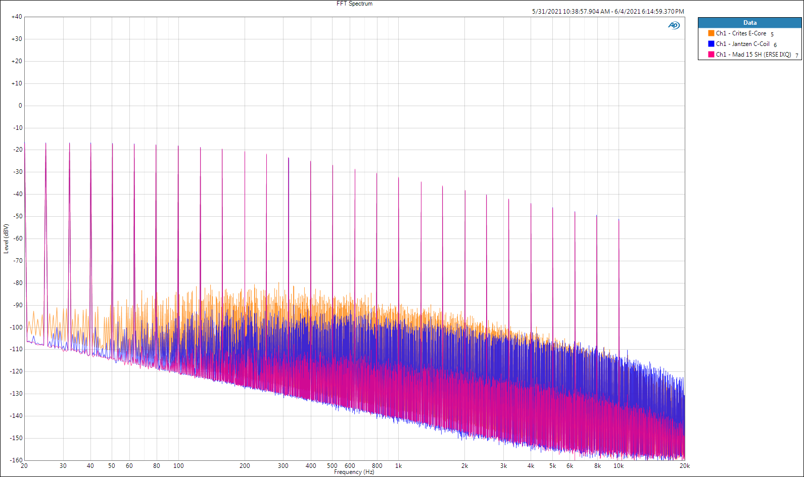
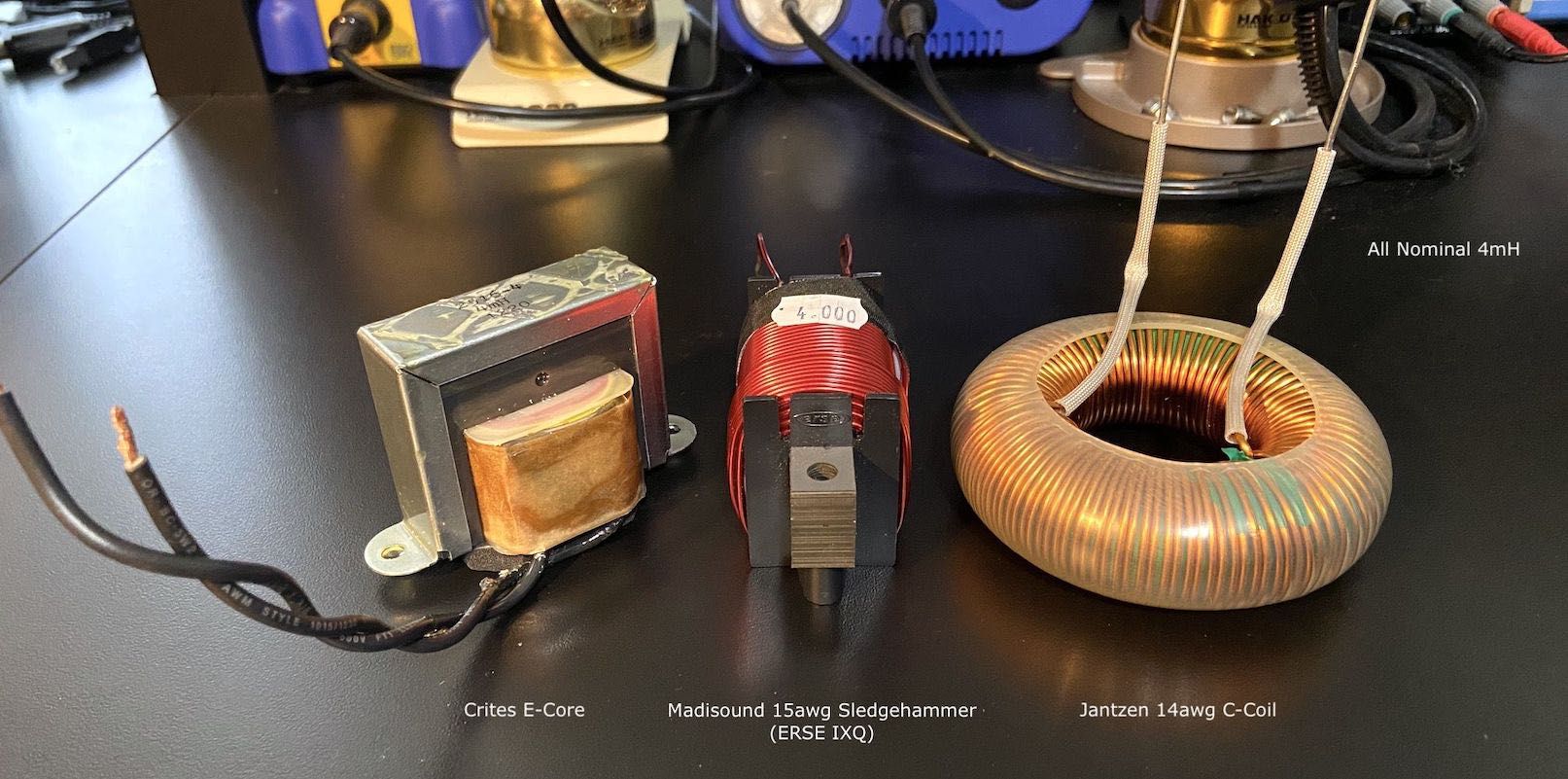
Today's Contenders L (1kHz) Q (1kHz) DCR Price 1. Crites E-Core: 4.077mH 17.8 0.4626Ω $19.00 2. Madisound 15awg SH: 3.963mH 33.0 0.2473Ω $20.70 3. Jantzen 14awg C-Coil: 3.478mH 9.2 0.0690Ω $54.98 (Keysight U1733C LCR meter) Inductance values 15% off spec better not be normal for Jantzen. Both C-Coils were labeled 3.9mH, one was as above, the other was 3.327mH. Conclusions 1. The 15awg Madisound Sledgehammer is an OEM ERSE IXQ inductor and it is the best performer by a large margin. If available with an acceptable DCR for your design, I doubt you'll find better regardless of cost (yes Virginia, that is a challenge). These are the only cored inductors to date that I'd consider as an alternative to air core in mid and high passbands. Secure them with stainless #10 bolts through the holes provided at either end and you're good to go. 2. My personal favorite is the Crites inductor that Bob worked with Universal Transformers to produce. They are tied with the IXQ as smallest and easiest to place, and the Crites seems completely immune to nearby ferrous material - which also means it transmits little magnetic interference. The build quality is second to none and with the varnish they're dipped it in it'll last a lot longer than any loudspeaker. The downside in my application is the DCR of 0.46Ω which would cost me a little over 1dB from the Klipschorn bass cabinet compared to the inductor I selected. 3. In highly efficient loudspeakers any of the (6) inductors I've reviewed will do well and their measurable differences will very likely be inaudible if placed properly in the system. With the ERSE IQ series, I'd heed Deang's warning and arrange a way to keep the plates from shifting (actually I'd just spend a little more for the IXQ). In less efficient loudspeakers where the inductor will pass peak currents exceeding a couple of amps, I suspect the distortion differences will become noticeable. THD You know the drill, this a marketing dept. measurement (for inductors) that I use to ballpark maximum current capability. One thing that the THD sweep was helpful for in this case was revealing a tiny resonance near 600Hz in the IXQ when passing an insane 16.6 amps (1.1kW into 4Ω) through it. The second IXQ sample had the resonance centered around 450Hz at that same "Honey! Get the fire extinguisher!" level. It's all quiet on the Western Front at lower levels. Fastening the units with stainless #10 bolts to stiffen the plates didn't help (or hurt). Finally, the C-Coil showed something similar around 1.2kHz. IMD I'd be very happy with any of these coils in my system. Again, my threshold of acceptance is 0.5% for this nasty and prevalent form of distortion. In my case I went with the Jantzen because of its near zero DCR. Multitone Multitone was born from engineers that wanted to take two-tone IMD to the next level, thus it's not surprising to see the results below tracking what we saw above. If you really want to know what's going on here you'll have to read through my earlier posts in this thread. I didn't repeat myself. Well, not that much. : ) I'm amazed at how hard it is to find objective comparisons of loudspeaker inductors or even objective data on them. I hope I filled in some gaps for you, it certainly did for me. God bless you and your precious family - Langston If someone separated the art of counting and measuring and weighing from all the other arts, what was left of each (of the others) would be, so to speak, insignificant. - Plato
-
Heil Air motion transformer for Cornwalls
Langston replied to jwgorman's topic in Technical/Restorations
Just for fun.. I videoed a Heil AMT in action at 750Hz driven by 3 watts (4Ω) just to see what the pleats were really doing. I used a frequency adjustable stroboscope to visually slow down the motion of the pleats, but this is a real time video - thus the irritating 750Hz is there to hear as well. I suggest muting your computer speakers and running the video in a loop. Heil AMT in Action What I noticed Approx. the 20% top and bottom of diaphragm moves very little, thus the primary output produced by middle 60% section. Additionally, approx. 20% outside edges of diaphragm move very little as well. This would be due to the magnetics or edge stiffness or both. Downside: reduced max SPL at a given distortion level. Upside: the reduced drive area acts like a smaller tweeter, thus resulting in wider dispersion. God bless you and your precious family - Langston -
Quartet with Crites modded crossover killing midrange driver
Langston replied to sparks12kv's topic in Technical/Restorations
You may be right about the cause, but it is possible that the replacement diaphragm was at fault. There was a several year period when the K77 tweeter was unrepairable according to my conversation with Bob Crites. He was one of the most knowledgable Klipsch guys on the planet, now his son runs things and is doing a great job. I mentioned the K77 diaphragm replacement available from Simply Speakers to Bob and he told me he tried several of them and they were inconsistent Chinese junk. Not that this proves everything from Simply Speakers is junk - but those diaphragms were. Like an idiot, I through away my K77's thinking they were history and now you can get the proper diaphragm replacements from Crites and others! : ) You really are going to need to make frequency response measurements of the voltage being supplied to the drivers. Do you know anyone that can do that for you? Welcome BTW! I'm a newbie too. Edit: I realize a K77 isn't involved here, it's just an anecdotal data point to illustrate that the problem might not be the crossover. I'm an idiot regardless! : ) -
Cranky soldermeister is right! At least the first part - I'd have to see some of your solder work to opine on the other (meister is German for master) : ) You just answered a question I've had about some Danley passive crossovers I replaced with my own a few years ago. They used ERSE 14awg IXQ steel plate cores that add mounting holes through the plates at either end, but they mounted them on a bed of silicone glue with wire ties and filled those holes. Why fill the holes? I think you nailed it - to keep the plates from shifting. I disagree with you about mutual inductance being purposeful, 'cause it's bad. How bad from an audibility point of view will vary, but I bet that input cup mounted three way crossover in my Heresy II's screws up the mids audibly. If you mean by "mutual inductance" the presence of nearby ferrous material or unmodulated magnetic fields (driver magnets), you're probably right and it's on the dog. Mutual inductance between (air core especially) inductors can be a big deal when modulated by audio. My measurements thus far show the skirts of mid and high pass passive networks beginning to fall apart -30dB to -50dB below the passband primarily due to poorly placed low pass inductor(s). You may say that's not audible, and I'd agree, but the crosstalk is different in phase, not just amplitude AND it's imbedded throughout the adjacent passband, not just the skirts, even if it's not apparent in the trace. That also means if you can hear some of the crosstalk, it'll be like IMD - unmusical - ugly - my guess is "grainy". Can you imagine a preamplifier or amplifier or active crossover manufacturer trying to sell a product that included the same kind and level of crosstalk between channels? They'd be bankrupt quicker than a knife fight in a phone booth (unless they plated the turd in gold and gave it a name like "Jupiter" or something.) Refrain: Why not do the best with what we have to work with? BTW, the Sledgehammer will arrive today (it looks to be ERSE IXQ OEM, TBD) that'll allow me to finish the shootout with the final (3) inductors. Cranky measurementmeister - Langston : )
-
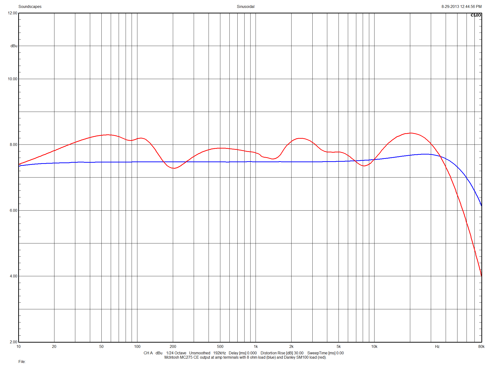
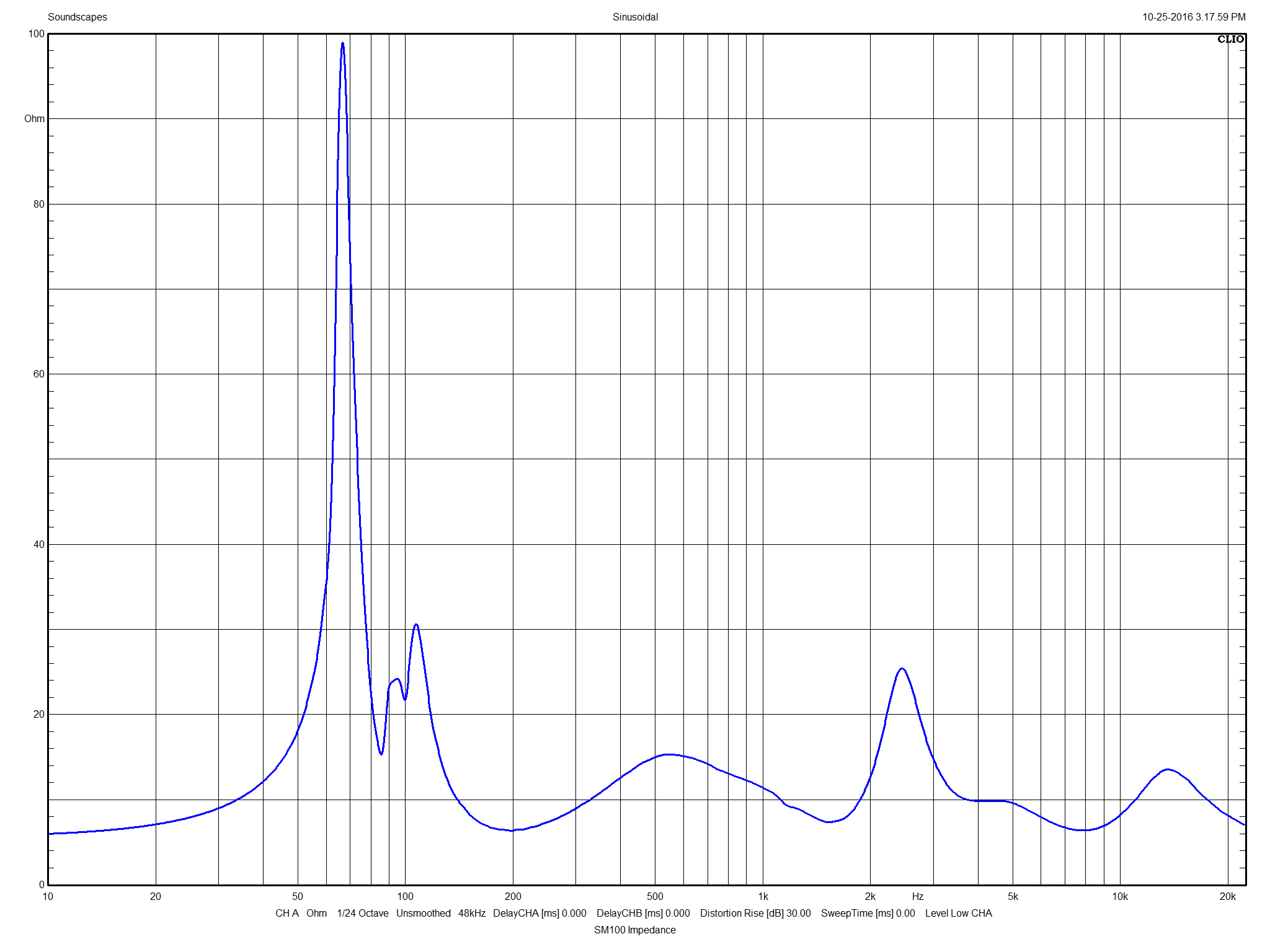
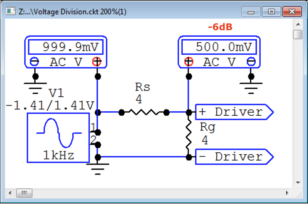
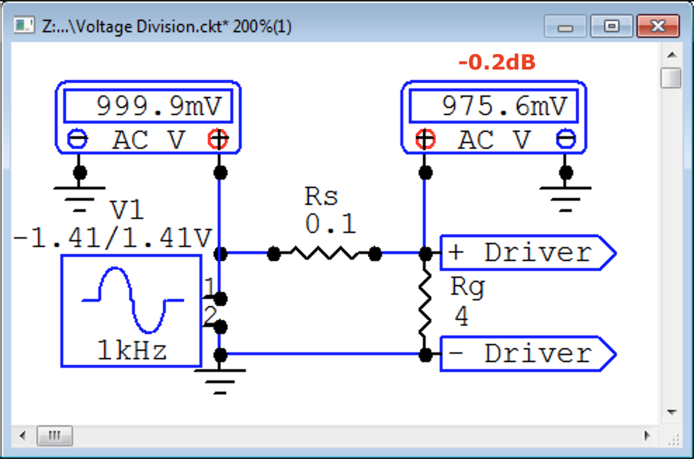
Nailed it. Good illustrations too. : ) Amplifier damping factor is wildly misleading. There is so much additional resistance in the round trip from amplifier to loudspeaker that even an amplifier output impedance of zero (infinite damping factor) is useless for increased driver damping. Good amplifier design will nevertheless minimize output impedance (increase damping factor), BUT the benefit of that lies behind door #2! The damping of a moving coil loudspeaker diaphragm is almost totally in the hands of the driver design and the box design. Stated differently, how long it takes a driver to stop moving after a pulse has little to do with the amplifier's output impedance (a.k.a. damping factor). Horn-loaded passbands (all of them in the case of the Klipschorn) provide huge amounts of stopping force (damping) after a pulse due to the vastly increased acoustic impedance on the front side of the driver. Well designed horn-loaded subwoofers (Danley's tapped horns for example) are so realistic that they often aren't acceptable in concert work because people are used to the sloppy "BOOOOMMM" of a kick drum from ported designs. Since damping factor is calculated by dividing 8Ω by the amplifier's output impedance, and since we know that even a zero output impedance won't help damp the loudspeaker, let's stop talking about "damping factor" and just talk amplifier output impedance. So what's behind door #2? Voltage Division! (and trying to avoiding it) Think about two equal value resistors that cut the voltage coming from the amplifier to the loudspeaker in half. That's a 6dB reduction is SPL. Huge. We generally perceive a 9dB reduction as half the loudness and +9dB as twice the loudness. I easily hear 0.5dB volume differences in quiet listening rooms and I ain't no spring chicken. The rocket-science equation (tongue in cheek) is: Rg/(Rs+Rg). Rg = loudspeaker driver. Rs = total round-trip resistances before the loudspeaker driver. Now what if the total round-trip resistances before the loudspeaker decreased to 0.1Ω? (damping factor of 80 (8/0.1) No audible reduction in volume! What if Rg (the loudspeaker) doesn't have a constant impedance? Answer: a tube type amplifier with a high output impedance will drive the loudspeaker at different volumes DEPENDING ON FREQUENCY. Not good. Probably. Now a real world example. This is the impedance plot (Rg) of a Danley SM100. Now let's look at the varying frequency response of the loudspeaker CAUSED BY a high amplifier output impedance. "Oh, but my tube amp sounds so much better than my solid state amp". I believe you, but the main reason is the variable EQ the tube amp is providing through voltage division with the varying impedance of the loudspeaker. Different loudspeaker cables may vary this EQ further. If you want to do a fair shootout between tube and solid state amps, you need to use loudspeakers with very flat impedance curves. @Bubo implied this in his post and @314carpenter explained the voltage division issue perfectly. I hope the plots of the effect on a real loudspeaker are helpful. God bless you and your precious family - Langston
-
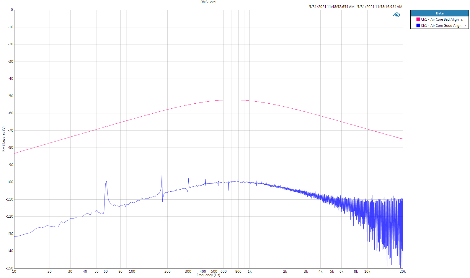
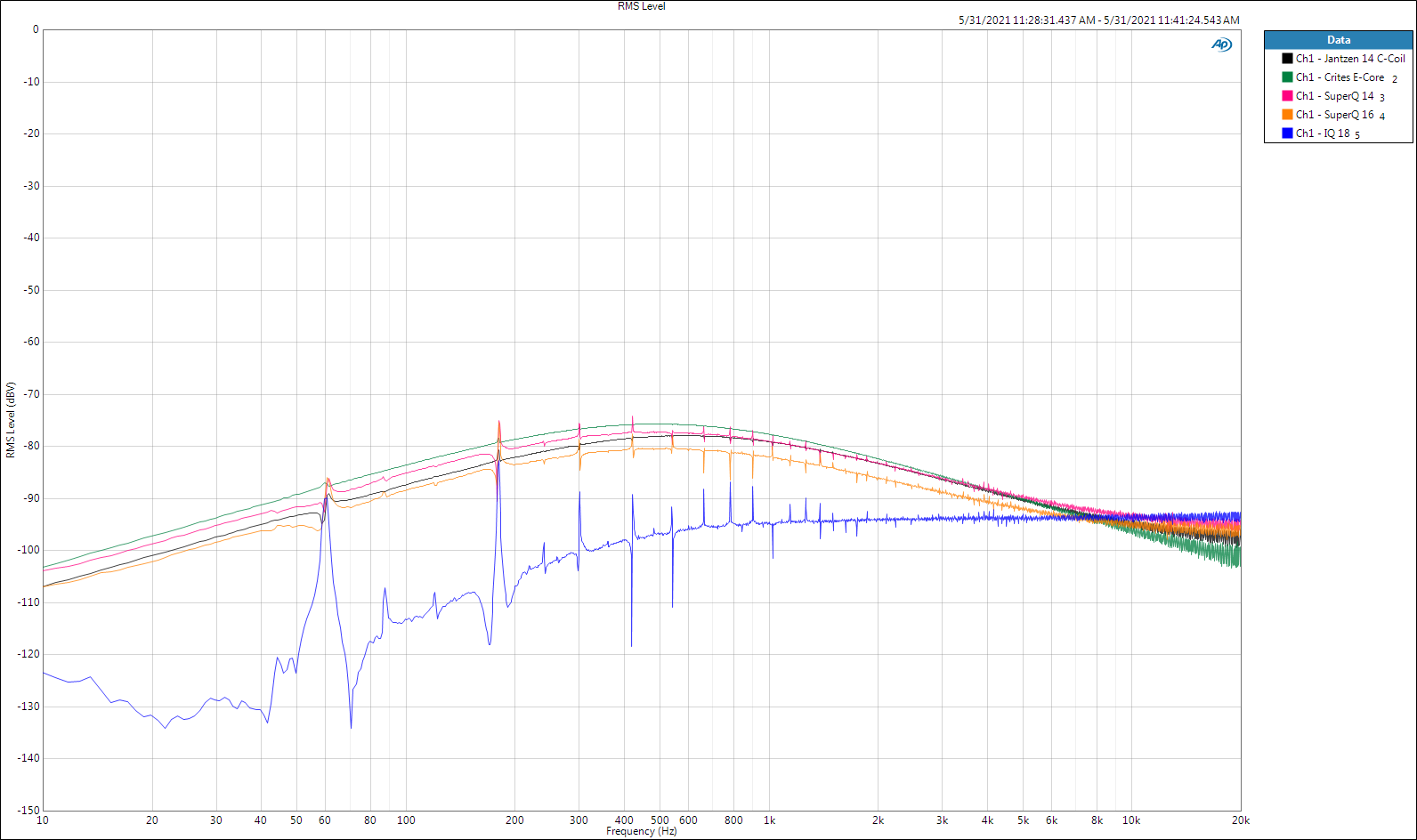
As kind of an intermission until the last inductor arrives, I'm going to show a couple of magnetic coupling measurements that I already posted the setup pictures of. Nothing ground breaking here, but crosstalk between passbands will compromise a whole lot of time, effort and money. Is it audible? A lot of designs pretend it isn't. Why not do the best with what we have to work with? EAW in its glory days was famous for excellent passive crossovers, and it wasn't just component quality. They oriented inductors for minimal crosstalk and mounted each passband on different boards displaced throughout the cabinet. The last inductor will be a Madisound Sledgehammer 15awg laminated steel core of very similar design to the ERSE IQ (or according to the pictures, the IXQ). Kudos to Parts Express and ERSE for quick shipping. I drove the transmitting 18awg air core inductor with 2V through a 10 ohm resistor, once again because this is where we listen with efficient loudspeakers. Then I separated the transmitter from the receiving inductor by 6 inches, center to center. Lastly, I spun the receiver around until I found the least pickup orientation and made the measurement. Cored inductors behave very differently than air core. For a given inductance, they transmit and receive less magnetic flux and thus are easier to place. They are also far less affected by nearby ferrous material and fields. I'm no magnetic scientist, this is what I observed fooling around with this stuff. Another thing I noticed was that air cores develop textbook like fields around them (the right-hand rule is a must-know) where there is one exact orientation between a pair of them that yields the least crosstalk. Cored inductors are much more forgiving, on the other hand, they don't have a perfect null location. Audio engineering is all about reasoned compromise, or as Heyser said, playing the part of a magician. That means hiding the ugly from perception while drawing attention to the beautiful. : ) All the cored inductors under test did well. The humble little 18awg IQ coil was best. Again. Ignore the power line frequency EMI spikes at very low levels - that's from my busy lab, not the transmitting coil. Now you know how field strength meters work. : ) Air core to air core, ¡mano a mano! These things will marry each other if you're not careful. God bless you and your precious family - Langston
-
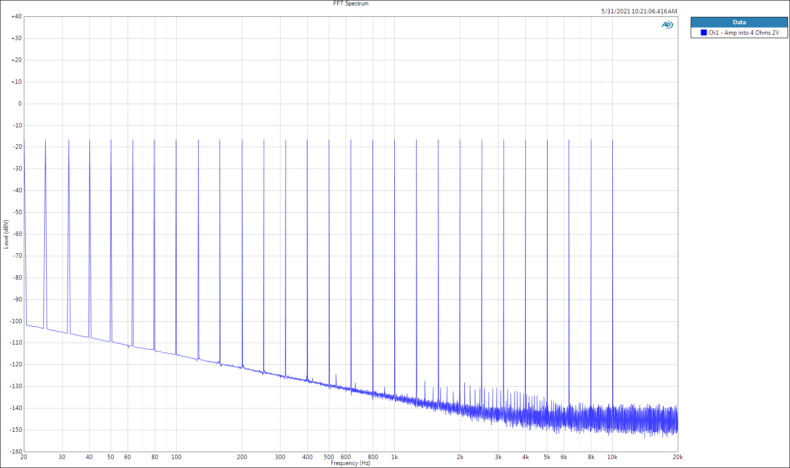
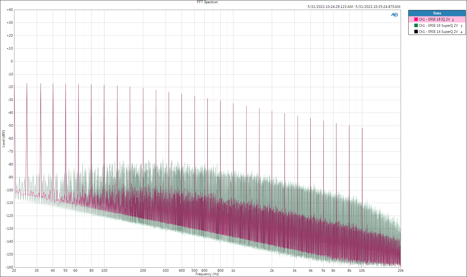
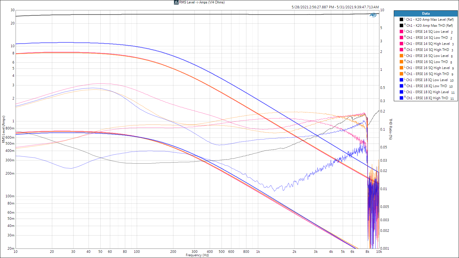
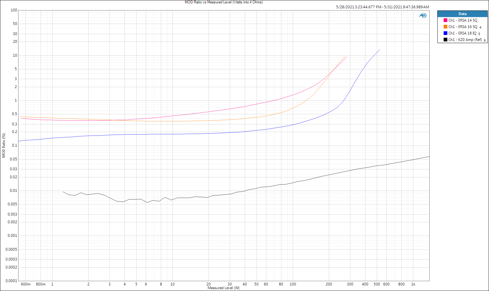
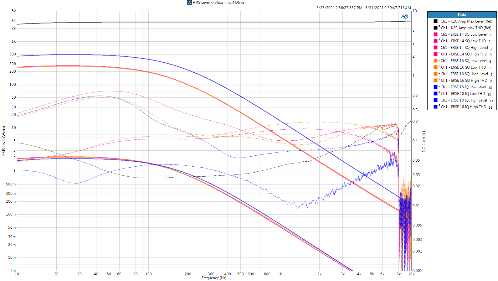
Today's Contenders L (1kHz) Q (1kHz) DCR Price 1. ERSE 14awg SuperQ: 4.004mH 21.0 0.1563Ω $18.55 2. ERSE 16awg SuperQ: 3.849mH 18.1 0.2266Ω $11.80 3. ERSE 18awg IQ: 4.014mH 29.9 0.4004Ω $5.02 (Keysight U1733C LCR meter) Conclusions 1. Best to worst follows price. Inversely! DCR alone improves with increasing cost. On the first point, I don't know why, I only have guesses. Someone that's into magnetics needs to chime in. 2. Bubo's post makes a fundamental point - keep your eye on the big picture when comparing inductors for highly efficient loudspeaker systems. If your inductor will never need to pass peaks exceeding about 2 amps (15 watts into 4Ω), any of these coils will do nicely and you can focus on DCR. THD Don't be suckered by THD for inductors (see earlier posts for why). It's only a first step in finding maximum current before ugly. I define ugly as >0.5% because (a) it's easy to stay under this hurdle with modern components, and (b) I'm confident that the cumulative ugly will remain inaudible with such components relative to even the best driver/box/room contributions. Secondly, don't be suckered by wattage specs for inductors. That's the marketing dept. talking. Inductors are current animals. They saturate (ugly) at a given current level. Watts equals current(squared) times load resistance. Thus an 8Ω max will be twice the wattage of the 4Ω max. Same current passing through the inductor in either case. Because I'm a sucker, I include wattage plots below to make it easier to compare with mfg. specs. BTW, the ERSE's THD specs using their 8Ω loads are accurate. Good for them. The problems is that THD and wattage are reasonably close to useless for these devices. IMD This is the reference metric I've chosen for inductor current capability (see earlier posts for why). Unfortunately there's no easy way I know of to display IMD levels in amps, thus you're stuck with watts into 4Ω. If you want amps, divide watts by 4, then take the square root of that. If you want the 8Ω wattage, multiply the 4Ω number by 2. Observation The THD measurements of the 14awg SuperQ inductor indicate it'll pass about 8 amps (256 watts into 4Ω) with acceptable distortion. IMD measurement say's it'll get ugly beyond about 2 amps (15 watts int 4Ω). IMD is counting distortion components in the audible passband of the device and THD is mostly counting distortion that is being suppressed in the rolloff. Which one are you going to trust? We already know which one the marketing dept. chose. Multitone This is like two-tone IMD on steroids. No one seems to know how to put this into a distortion metric that works across devices and domains the way THD, IMD and others do. You can take a known good and compare it with other like devices with excellent repeatability using the multitone "TD+N" metric. Since I don't do stuff repetitively like a mfg., I normally just inspect the multitone spectrum to see the stuff that piles up between the generated tones. That stuff shouldn't be there. How much until it's audible? Depends on the device (i.e. I have no stinkin' idea). Here's the reference amp's behavior driving a 4Ω resistor with 2V. This includes cabling and adapters and the very low level HF stuff may be due to the latter acting as an EMI antenna. The low drive level is representative of where we listen, so I'm not going to bother you with the high level plots (same horse wins). Both SuperQ's produce virtually identical responses, the little IQ is highlighted so you can see it in the foreground (pink). With ERSE cored inductors, cheap is cheerful. God bless you and your precious family - Langston
-
Full bandwidth impedance measurements are the best way to verify driver motor health. Of course you'll need curves of known good drivers for comparison. A defective diaphragm will mask the results of an otherwise good motor (magnet). Acoustic measurements are not as reliable an indicator of driver health, but I'd do that too and compare to known good curves. Measurements will need to be done well (at as low a drive level as possible while maintaining reasonable S/N). Otherwise GIGO. Good luck! God bless you and your precious family - Langston
-
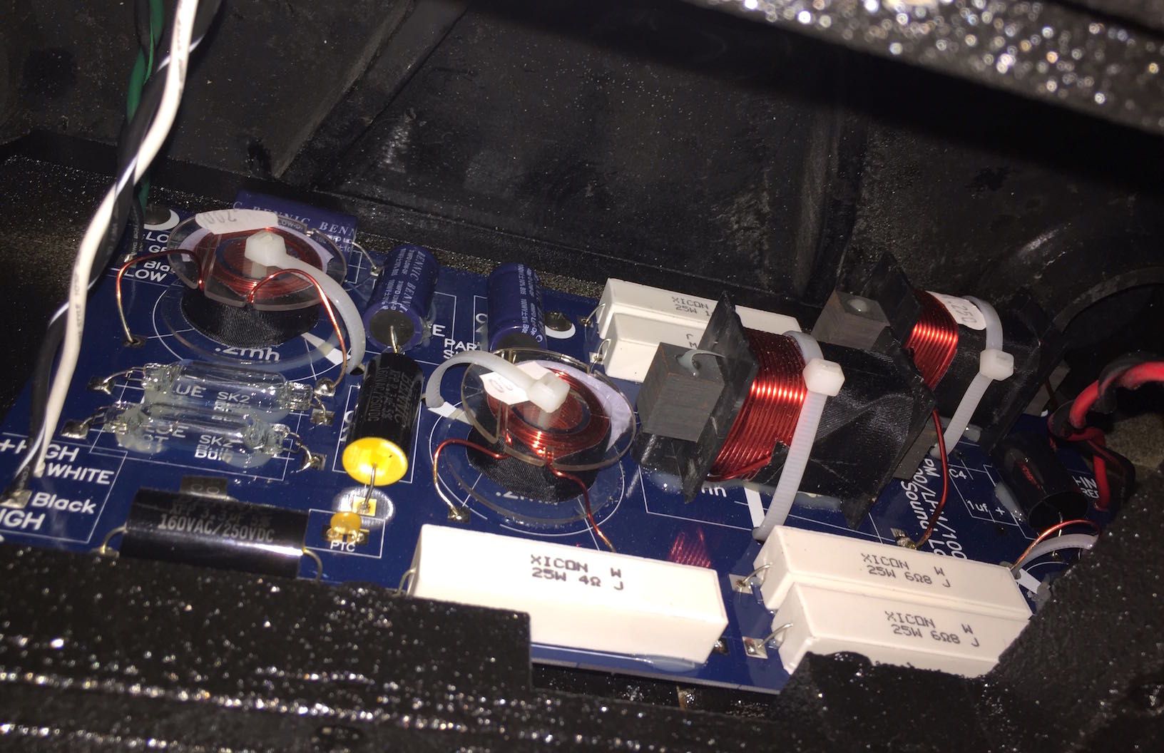
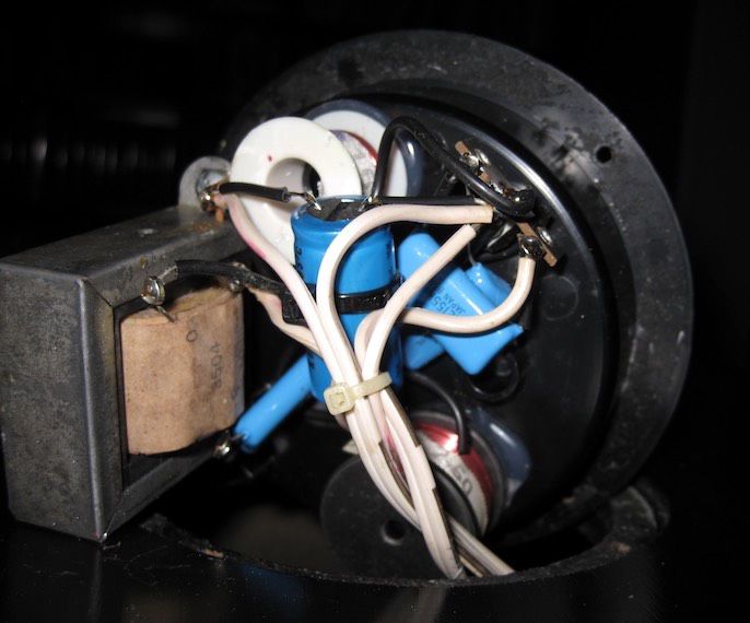
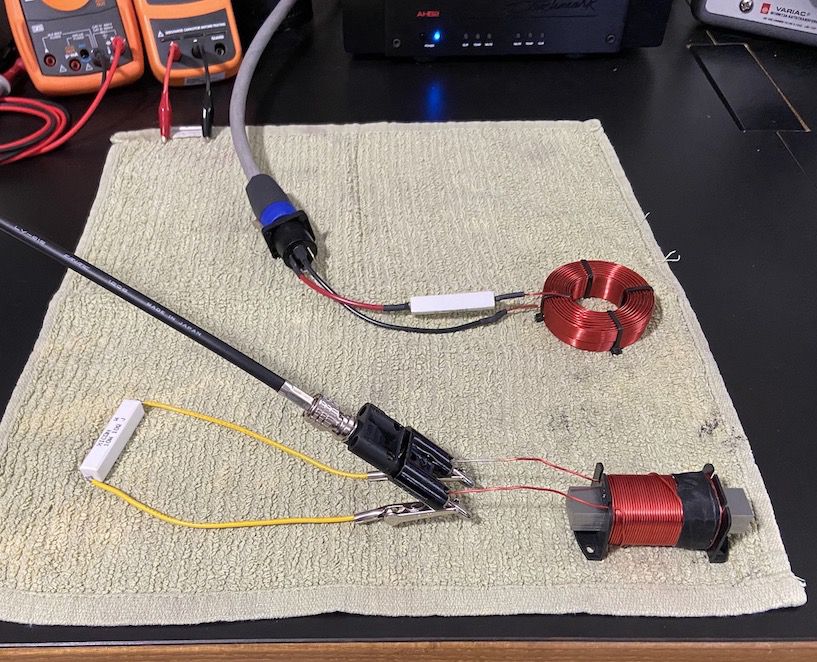
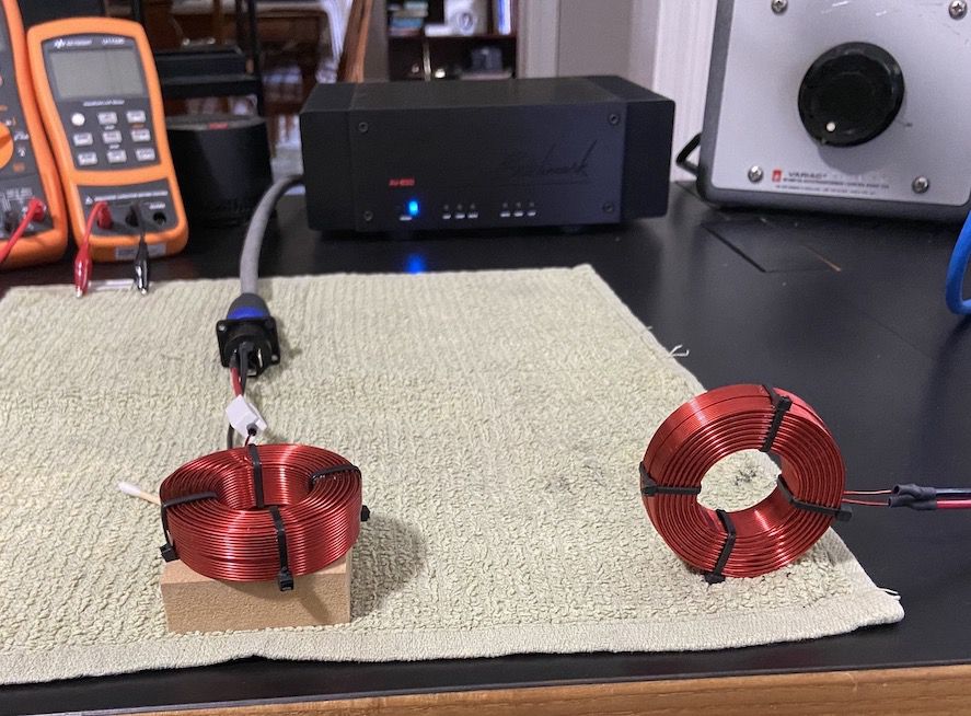
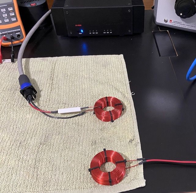
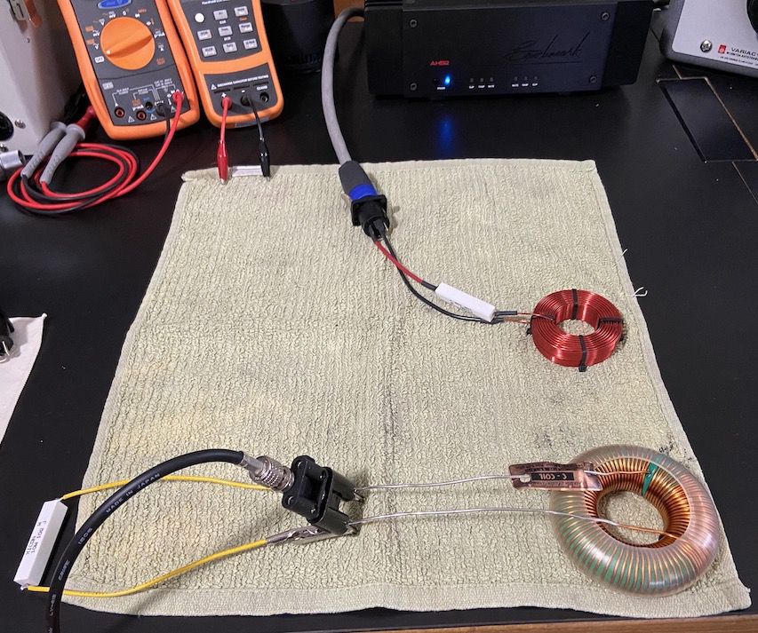
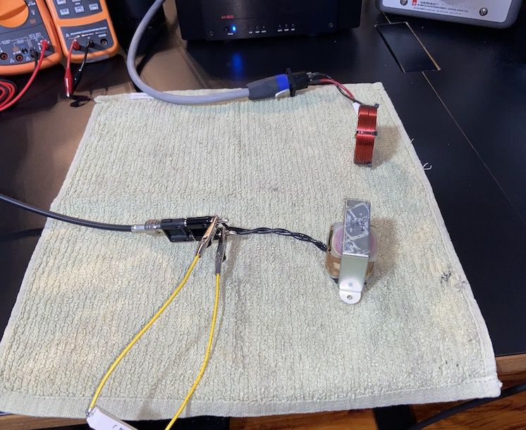
The following are pictures of the inductor measurement setups. I hope this will help along with the discussion in my prior posts in this thread to better understand what's going on. I hope breaking it up like this makes it tolerable. Tomorrow I'll post actual measurement plots. I've gained huge respect for passive crossover engineering. It adds dozens of variables that active crossovers avoid. I'm enjoying it quite a bit. : ) Distortion Testing Audio Precision APx515 AES3 out to Powersoft K20 amplifier (DSP bypassed). The ERSE 18awg IQ laminated steel inductor in the picture is in series with the positive amp output and then connected to the 4Ω power resistor, and the resistor's remaining wire is connected to the amp's negative (it is ground referenced, not bridged). Voltage is read across the resistor. Divide the voltage by 4 (the resistor's value) and you get current. Ohm's law. There's also a Benchmark AHB2 amp involved that I use for most stuff because John Siau forgot to design noise and distortion into it. Magnetic Coupling I also measured magnetic interference sensitivity using the various cored inductors as receivers and a 2.4mH air core as the transmitter. I drove the transmitting inductor with 2V through a 10Ω resistor and I paralleled the output of each receiving inductor with 10Ω to simulate a loudspeaker load. I oriented each receiving inductor for minimum pickup before recording the result. I used 2 second sweeps from 10Hz to 20kHz. The transmitting and receiving inductors are separated by 6 inches, center to center. I've seen many pictures of passive crossovers on this forum with the inductors physically aligned very poorly with each other... The (3) ERSE laminated steel core inductors aligned for least coupling looked like this The Crites E-Core laminated steel inductor The Jantzen 14awg C-Coil (actually toroid) inductor My Air Core test inductors, both 18awg and 2.4mH, in proper alignment for least coupling. Not easy to do, 1 degree off will cost you at least 10dB The wrong way, working like a weak transformer God bless you and your precious family - Langston
-
That was an amazing post. I'd hate to be an engineer at a for-profit loudspeaker company. : ) Thanks for the history and questions. I'm going to focus on just one thing in this thread - surveying readily available non-air cored inductors to see if it's possible to approach air-cored electrical performance without their downsides. Much (most?) of the fun of this for me is in the learning. A passing audible grade will be defined as no noticeable difference (to me) between an active low-pass and passive system with the same electrical transfer functions. This is probably achievable because I'm dealing with low frequencies where we have much less ability to hear distortion. I'm also standing or sitting and often falling off the shoulders of those who've gone before me with the measurement vs. audibility stuff. Heyser was all about that and in my feeble attempts, so am I. God bless you and your precious family - Langston I happen to believe that a major purpose of technical audio measurements is to assist in creating better subjective perception, and if that's not happening, then we are getting nowhere with the objective measurement - Richard C. Heyser
-
My wife says that! : ) In this case I'm taking a pair of 1974 Klipschorns and trying to do what I think PWK would do with them if he were here. There's stuff I'll get to in the future, but at the moment I'm simply trying to convey what I've learned about the worst offender in passive crossovers; the inductor. My conclusion will be that it's possible to find good ones, but you can't do it by reading advertisements or subjective reviews or assuming price = performance. Bottom line: anything in the signal chain that has ≥ 10dB less distortion than the moving elements of the loudspeaker system cannot be heard and can effectively be ignored (IMO). The brilliance of PWK was his fixation on the horn, which translates into minimal voice coil movement, which translates into less distortion. One of the things we did with concert production was bring "too much rig for the gig", thus we got no where near its limits, thus it sounded clean. What I'm doing here is making dead sure that voice coil/horn distortion is the only audible distortion in the system. Just for fun: Decibel Addition & Subtraction.pdf God bless you and your precious family - Langston Whether we like to think of it this way or not, an audio engineer shares the professional goal of a magician - Richard Heyser
-
That is a wise statement Deang - nothing offends the transduction from the electrical to acoustic domain as much as the moving coil loudspeaker itself. A close 2nd would be the room. Nevertheless, it's an interesting pursuit to reduce the electrical domain distortions as much as possible. A hundred tiny improvements = a slap in the face + it's fun. : )
-
I've chosen (3) measurements for inductors: 1. THD up to 0.5% from 10Hz to 20kHz. 2. IMD up to 0.5% using equal levels at 50Hz and 500Hz. 3. Multitone from 10Hz to 20kHz with 48,000 sample points (crazy high res). I'm using a Powersoft K20 amp through the coil under test, then into a 4Ω power resistor rated at 100W. I'm using 2 second THD sweeps that avoid heating the resistor too much even at 110V (3,000W), which is way more than any cored inductor can tolerate that I've come across. The amp is very comfortable at this level, thus doesn't pollute the results with distortion products of its own. THD Not the right tool for analysis due to the low pass characteristic of inductors. I found it useful to ballpark maximum current an inductor can handle prior to severe saturation. 0.5% THD fits the bill although it understates the actual distortion going on within an inductor's limited passband. IMD This has been the go-to for many years. Audio didn't use to have the bandwidth it has today and IMD was the primary way to assess distortion in limited bandwidth devices - it was also one of PWK's favorites. Stimulating the device with multiple tones is also more like what devices are exposed to in use and the harmonics that fall out of these tests have no harmonic relationship to music, thus sound terrible, thus is something you want to avoid, thus test for. IMD measurements can scream bloody murder when THD looks fine. Keeping IMD under 0.5% through the maximum current the inductor will see in use is the bottom line for me. This is what ERSE, Jantzen and others should be doing when they rate their inductors' maximums. I found several inductors that can't go under even 1% at ANY drive level. Multitone This is cool, but nobody really knows how to objectively correlate it among differing devices to how the devices will sound. Nevertheless, it is very telling to look at a bunch of simultaneously generated tones located in specific areas (it's complicated) and seeing the crap that fills the gaps between these tones. I think this is the future of objective distortion measurement once we figure it out. Sorry for all the words. : ) Next post will compare (3) 4mH steel plate cores (you'll be surprised): 1. ERSE IQ 18awg 2. ERSE SuperQ 16awg 3. ESRE SuperQ 14awg PS: You've heard this, but it's true - air cores are effectively perfect, you just have to deal with magnetic sensitivity, DCR, size and cost. God bless you and your precious family - Langston An experiment is a question which science poses to Nature, and a measurement is the recording of Nature’s answer - Max Planck
-
Thanks Wirruna - that's the primary thread that landed in my online search on the topic of inductor distortion, and after reading that and bunch of other stuff on this forum I decided to join if the moderators could be fooled into letting me in. : ) The whole cored inductor mess started when some very reputable coils measured poorly and some inexpensive ones measured well. I figured it would be a piece of cake selecting a cored 4mH inductor to precede the 130µF cap for my Klipschorn passive LP filter. Boy was I wrong. I'm working on the post now and will make the first installment an intro. to the measurement philosophy using a single inductor (edit: 3 inductors) as an example. Then I'll followup with the shootout. Bob Crites, grumpy Al and others revealed some great stuff in that thread you mentioned, they just didn't seal the deal for me. God bless you and your precious family - Langston I claim that it should be possible to measure audio systems and have those measurements correlate with what we hear out of those systems - Richard C. Heyser
-
I noticed that and thought about doing that myself at one point, but I happen to have a room that has close to perfect corners for my '74 models. A couple of thoughts: 1. I bet there'll be a difference with Z measurements even with the new ones in a corner vs. not, but less so. 2. Corner placement is still best for acoustic reasons when possible in most cases - nothing that hasn't been noted before of course. : ) God bless you and your precious family - Langston
-
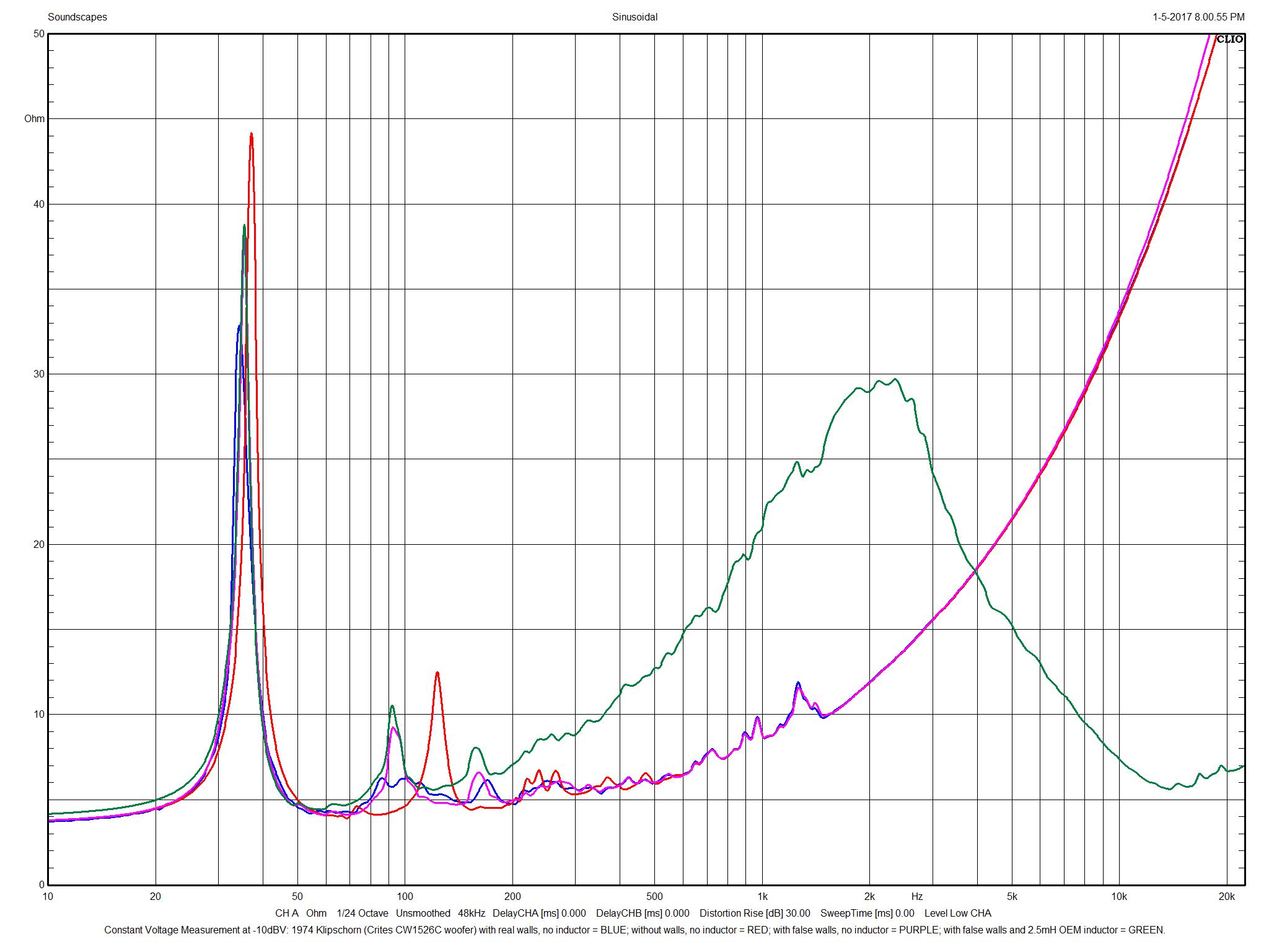
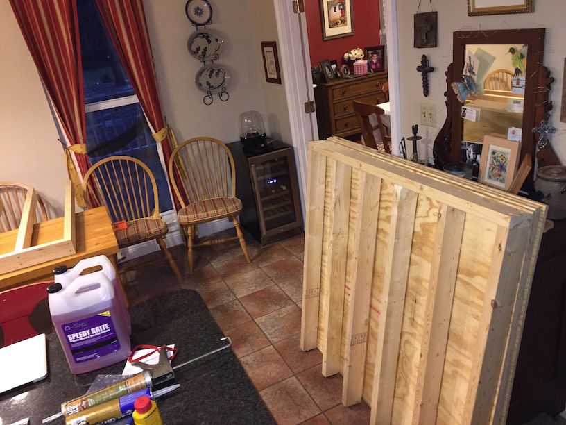
My 2nd post! : ) It's been two years since karlson3 asked if anyone had impedance measurements of the Klipschorn bass bin using the recommended false walls. I have that as well as overlays that replicate his measurements using real walls and no walls. There's excellent correlation between our measurements, which is interesting given that mine involve the cast frame Crites woofer and his may be using the OEM woofers. Bob and now Michael are gifts to vintage Klipsch owners. The measurement legend describes each trace by color. Also included are pictures of the false wall I built for acoustic measurement purposes. As you can see, you really need to use a real room with real walls to measure impedance properly, but those same walls are the enemy when trying to isolate a loudspeaker's acoustic response. Thus I built the false walls since I don't have access to that crazy anechoic chamber with the revolving corner. God bless you and your precious family - Langston
-
Hello: My first post here. Incredibly impressive forum on two counts - some genuinely serious audio (Chris A. and others) and secondly, rare for today, allowing some difficult conversations without censorship. I spent a few decades in pro audio (concert production) with the intent on bringing the best sound in the world to my audiences. Of course I rarely pulled it off, but I enjoyed the pursuit. : ) Much of the endeavor involved modifying the weakest link in the chain: loudspeakers. My hero in the realm is Dick Heyser and he did a review on the mighty Klipschorn in a 1986 Audio Magazine article and ever since then I wanted to purchase a pair and have a go at making them all they could be without violating PWK's vision. Now I'm retired and have the time to make a mess of home audio, so I found a very nice pair of 1974 vintage Klipschorns, Polk SDA SRS 1.2TL's, Martin Logan CLS II's and some other stuff. I'm into inverse filtering per Dave Gunness's work and I'm also a huge Tom Danley fan though and may end in his court, we'll see. --- What's my first post about? My stubbornness to stay with passive crossovers per the original Klipschorn design and thus have to deal with something I avoided with professional loudspeakers: cored inductors. Something this "simple" ended up taking much of a month to figure out and I'd like to share my findings. Sure, air core is the way to go as long as you keep them away from ferrous materials and magnetic fields. That's not so hard with the smaller values required for mids and highs, but at low frequencies, reasonable DCR is a challenge. I thought it would be easy getting a high quality 4mH cored inductor with less than 0.5Ω DCR for the Crites cast frame woofer (replaced the square magnet K-33P), but even some of the best of these generate too much distortion for my taste. --- What do I mean by distortion? To begin with, THD is a poor, but not quite useless distortion measurement for devices that exhibit natural low-pass characteristics; such as inductors and horn loaded bass cabinets. THD is all about comparing the unwanted odd and even harmonics to a fundamental, and the harmonics are largely filtered out! Thus you can get good THD numbers and still have audibly unacceptable levels of distortion with low pass devices. The solution is to measure distortion components within the passband of the device, and that can be done with intermodulation techniques that use two or more simultaneously generated tones within the passband to generate sum and difference frequencies as well as harmonics of the (two or more) fundamentals. I chose Audio Precision's "MOD" IMD measurement technique as well as a high resolution, low frequency Multitone stimulus to compare 4mH inductors loaded by a 4Ω power resistor. 4Ω is what the Klipschorn and a great majority of low frequency systems use, thus 8Ω wattage specifications tend to be marketing ploys IMO. Inductors are current limited animals, not wattage limited. An inductor that is clean at 10 amps into 4Ω behaves identically at 10 amps into 8Ω. Ohm's law states that Amps(squared) times resistance equals watts, thus the 8Ω load will provide the marketing department with twice the wattage specification compared to the more realistic 4Ω. --- It has been a personal endeavor to select a low DCR woofer inductor for my 2nd order (electrical) low pass filter. There is a 12awg copper foil air core inductor that boasts a 0.3Ω-ish DCR, but I wanted to learn about cored inductors, thus purchased the following 4mH coils (that's what their nominal spec's were, but the truth turned out to be 3.4mH - 4.2mH). 1. ERSE SuperQ 16awg 2. ERSE SuperQ 14awg 3. ERSE IQ 18awg 4. Jantzen C-coil 14awg 5. Madisound Sledgehammer 15awg 6. Crites Steel Core 0.46Ω DCR (don't know the awg yet, either 18 or 20) I won't have inductor #5 until 2 June. Would the results of my testing be of interest? God bless you and your precious families - Langston