captainbeefheart
-
Posts
1422 -
Joined
-
Last visited
Content Type
Forums
Events
Gallery
Everything posted by captainbeefheart
-
Wow factor fading – now looking to upgrade
captainbeefheart replied to Boston Chris's topic in Talkin' Tubes
It doesn't matter how good his source or source material is, The amplifier and speaker need to coherently transfer that information into sound pressure. I am not saying all sources are the same so don't get into that argument but reading his gear list the 300b amp will be his bottle neck for producing clean dynamic multi-instrument playback. I of course could be wrong but in my experience as a SET fan I have had plenty of bad experiences with lots of SET amps on the market. They all sounded fantastic with simple arrangement music but when put to the test with a full orchestra at Symphony hall levels it left me longing to get tickets to BSO and get the real thing. This journey over many decades has me spending as much time on my hobby as I do at my day job. Since you are in my neck of the woods I offer to bring an amp to your place for you to audition if you want. -
Type AA crossover rectangular capacitor replacement
captainbeefheart replied to Tizman's topic in Technical/Restorations
Many prefer the older AA crossover network including myself. The more advanced crossovers become the more they try and filter "unwanted" frequencies from a specific driver. But with Klipsch heritage models many of us just prefer the AA network vs the steeper AL network. Try the AA filter -
Type AA crossover rectangular capacitor replacement
captainbeefheart replied to Tizman's topic in Technical/Restorations
They purchase parts knowing the specification needed so that the inductor will not saturate under normal use, say up to 100 watts. The iron core vs air core was a no brainer for them really, the price is cheaper and there is less DCR for better damping. If they did get an air core with the same DCR and inductance it would be huge and expensive for no benefit. The problem is someone reads somewhere that air core does not suffer the same core interaction problems and so they are superior. Although this is true, it is much more prudent to just use an iron core inductor where it is sized appropriately to not saturate the core. You end up with the same low distortion signal but with lower DCR and for less money which the savings is passed onto the consumer. It's the same as someone reading that silver has a lower resistance vs copper. Yes this is true but instead of purchasing a silver cable it is much more prudent to just increase the size of the copper conductor and you will lower the resistance much more than just using silver. So a 14awg copper speaker cable, non-engineer says I know more than everyone because silver has less resistance so I am going to use 12awg silver. Besides even the cost of silver going with a 12awg copper will yield a lower resistance than 14awg silver. I know, why not just use 12awg silver cable, here is where price comes in, it is cheaper to just go down to 10awg copper. And don't say you will purchase 10awg silver cables, that is ridiculous but the same argument keeps going in circles, just go to an 8 or even 6awg copper conductor. Jumping up a size in copper is always better than switching conductor material. The layman says silver has lower resistance vs copper so it is better, you can't tell me otherwise. An engineer asks what are we trying to do? Lower resistance. Ok, well we could use silver but that is expensive and doesn't gain us much or we can just jump up a size in copper conductor and lower the resistance. The latter is the better way of doing it of course but don't tell an audiophile that, silver is always best so if you don't use silver you are not hearing your stereo at it's best. -
Type AA crossover rectangular capacitor replacement
captainbeefheart replied to Tizman's topic in Technical/Restorations
Maple has that syrupy sweet sound to them. Flamed maple has the same sweetness but with very hot aggressive top end. -
Type AA crossover rectangular capacitor replacement
captainbeefheart replied to Tizman's topic in Technical/Restorations
With a simple E core and the bobbin on the middle leg, there is usually a shim (most vintage was wood), pull it out, clean, and re-treat and install back in. -
Type AA crossover rectangular capacitor replacement
captainbeefheart replied to Tizman's topic in Technical/Restorations
Yes exactly!!! You can pull the wood shim out, clean and re-treat, sometimes still requiring some shimming. But really the easiest thing for any diy person is just shove some popsickle sticks between the wood block and core, the popsickle is a good thickness for a shim to tighten snug things up. -
Type AA crossover rectangular capacitor replacement
captainbeefheart replied to Tizman's topic in Technical/Restorations
That was not meant for a tech fix but for an owner that just wants to tighten it up easily. A tech should be able to secure the bobbin to the core more professionally of course. My point being there is no reason to chuck a transformer in the trash because the bobbin is a little loose. -
Wow factor fading – now looking to upgrade
captainbeefheart replied to Boston Chris's topic in Talkin' Tubes
Sadly SET amps get a bad rap because 90% or more on the market are not really designed well. They do great with simple music but loose coherence with complex music plus it probably isn't controlling the Heresy woofer all that great. I don't think a Cornwall or any speaker with a normal cone woofer like the heresy will pair well with your SET amp. So you either need to get something like a LaScala with a horn woofer with less mass to have to control, these pair well with your average SET amplifiers. Or, you need to find a different SET amplifier with lower output impedance and possibly one that does A2 operation. People do not realize how much they go into clipping region even if it's for short transient duration the effect will be poor imaging and sound stage since blocking distortion and bias shift throws the amplifier into a tail spin until it recovers. fwiw I am in the Boston area and if your wife gives the green light I have a nice pair of LaScalas that I have been toying around with the idea of selling. I am actually in the same boat with trying to convince the wife to swap the Klipsch reference floor stands in the living room to the LaScalas so we can keep them but she hates the look of them, the reference floor stands have a more contemporary look and are smaller so she is ok with them. You could possibly modify your current amplifier to work better with the Heresy but you need to bring it to more an engineer vs a repair tech, I have done this for people with the same problem. All that is needed was a few resistors and maybe 1 or 2 capacitors, last one went from a damping factor of 5 to a DF of 100 that made a huge improvement. -
Type AA crossover rectangular capacitor replacement
captainbeefheart replied to Tizman's topic in Technical/Restorations
Whenever I have seen this the woofer jumps about a mile from the transient "thump", didn't think this would effect the tweeter since the transients measured were low frequency hence the woofer excursion. I suppose it could be more of a "pop" than a thump that would maybe hit the tweeters. Muting circuits are our friends and this is why. Are we talking about the bobbin being a little loose with an EI core? If the bobbin is loose it shouldn't be much of an issue, just wedge some popsicle stick or any small wood between the core and bobbin, happens all the time and not a big deal. -
Type AA crossover rectangular capacitor replacement
captainbeefheart replied to Tizman's topic in Technical/Restorations
Yep, high powered, high distortion at high frequencies when clipping, and unstable oscillations started blowing much more tweeters vs tube predecessors. -
Type AA crossover rectangular capacitor replacement
captainbeefheart replied to Tizman's topic in Technical/Restorations
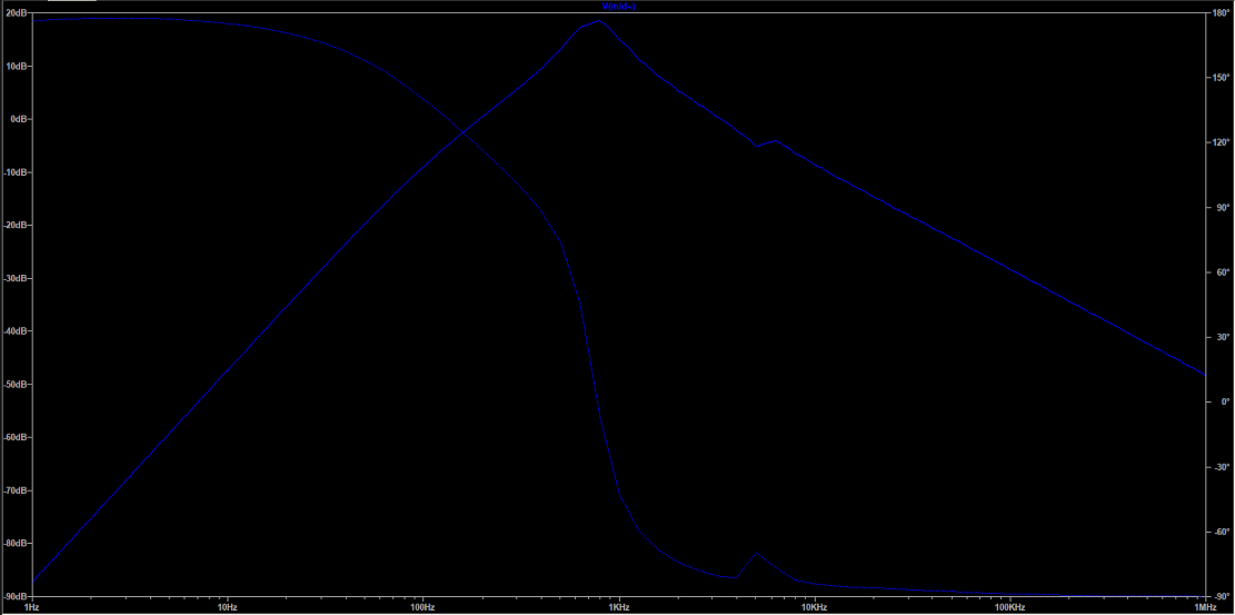
Take a look at the third picture down of the tweeter frequency response I posted 4 posts ago, you can easily see this bump at 9kHz. I can simulate whatever you want to try so you can see what will happen. I will add an inductor into the simulation where you suggest to see what happens. -
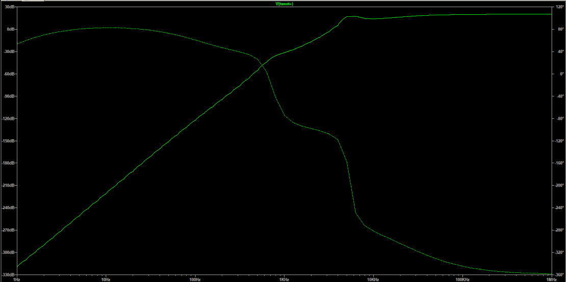
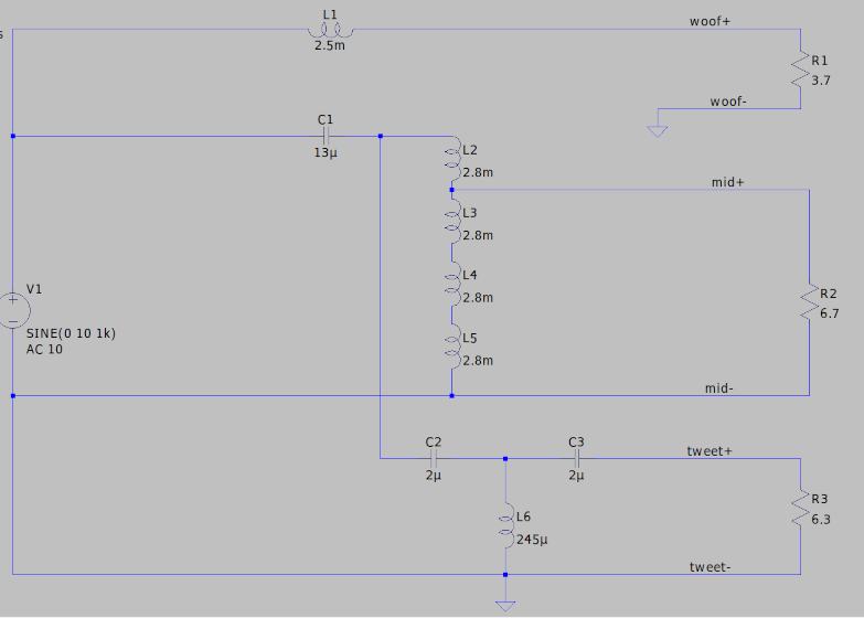
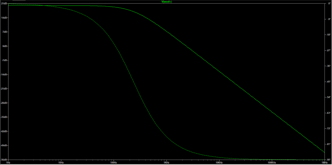
I hope this finds itself useful for the folks doing work on Klipsch crossovers. I can simulate other models as well if there is an interest, I did the AA network because it seems to be the most popular for heritage models. Pictures are in the order like the schematic from top to bottom; 1) woofer 2) mid 3) tweeter Viewing them in this order you can see how they overlap each other to cover the whole audible frequency range. This is how I test crossover networks, I place the signal generator output to the input of the crossover, I then put resistive loads on each output and then use a frequency analyzer to look at and compare the frequency response of the networks to make sure they are functioning properly. This gives you a great indication of which filter is having a problem so less time taking the whole board apart and testing each component. I also leave my scope on the outputs in chop mode and compare to the input, sometimes you will see an ugly waveform at the output with high distortion, a good indication a component is toast.

-
Type AA crossover rectangular capacitor replacement
captainbeefheart replied to Tizman's topic in Technical/Restorations
For anyone curious what the filters should look like at each output here you go. I used the drivers DCR as a resistive load, when I take them out of the speaker this is how I test them with a load. There are free signal analyzers for your computer, all you need is a decent sound card and make sure you do not input too much signal into the sound card. You can easily sweep these crossovers with just a 2v input and all the outputs will be safe for your sound card. During testing take screenshots of the tests then compare against the simulation. The order of pictures follows the schematic; 1) woofer 2) mid 3) tweeter
-
Type AA crossover rectangular capacitor replacement
captainbeefheart replied to Tizman's topic in Technical/Restorations
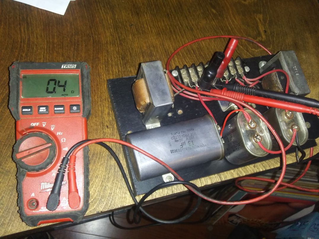
You would have to place them in series to get the inductance you want, they are the reciprocal of a capacitor remember. You would have to measure/calculate the DCR of them all in series to get an idea if it's worth it. Here is my XO, my meter reads .4 ohms and that is with the cheapo long test probe cables which most likely add .1 to the total, so in actuality the stock core inductor is more like .3 ohms.
-
Type AA crossover rectangular capacitor replacement
captainbeefheart replied to Tizman's topic in Technical/Restorations
I agree about keeping the old boards original an build some new boards. Someone like myself would prefer the old crossover network if purchasing the Khorns from you. -
Type AA crossover rectangular capacitor replacement
captainbeefheart replied to Tizman's topic in Technical/Restorations
That is double what my 2.5mH inductor measures in my LaScala AA network, I just measured .5 ohms. So the air core you have will add some resistance and reduce your damping factor for less speaker control. I don't think it is worth it personally but try both and see what you like. -
Type AA crossover rectangular capacitor replacement
captainbeefheart replied to Tizman's topic in Technical/Restorations
1000Hz is much better for testing the 13uF capacitor, at least that is in the region of useful frequencies to test at. For the 2uF you want to test ESR between 5kHz and 20kHz. -
Type AA crossover rectangular capacitor replacement
captainbeefheart replied to Tizman's topic in Technical/Restorations
Check the DCR of that air core inductor and compare it to the stock inductor, I highly doubt you are bringing the stock one into core saturation which is the only benefit of having an air core inductor, no core interaction. The air core will add resistance into the woofer circuit lowering your damping factor and increasing the loss across it. They make super core inductors with extremely low DC resistance that won't saturate the core, I would choose those over an air core any day of the week. -
Type AA crossover rectangular capacitor replacement
captainbeefheart replied to Tizman's topic in Technical/Restorations
Tizman- if you do end up replacing the capacitors please message me as I would like your old ones as spares for my original crossovers. I like the Aerovox caps. The 13uF is an odd value to find today so I wouldn't mind some spares if mine go south. At the very least I will spend the time to see if they are worth keeping as backups instead of just blindly throwing them in the trash. -
Type AA crossover rectangular capacitor replacement
captainbeefheart replied to Tizman's topic in Technical/Restorations
If you test with one of those hand held ESR cap testers they only test at one frequency and it's almost always at power supply ripple frequencies like 100-120Hz, you will be fooled by the readings thinking they are bad because and ESR of 7 at 120Hz means nothing in this application where you want to pass high frequencies. You want to test ESR for the 13uF at 500Hz and up, the 2uF test at 5kHz and up. You can easily see how ESR effects things with an equivalent model, I have shown on here before. For example even if the ESR is 1 for the 2uF caps it will only have a loss of 1% of signal, usually you are -6db at 5kHz from input of xo to tweeter taps, 1 ohm extra puts the signal from 63% to 62%. I can post all this stuff again. The thing is the 2uF are easy to find but the 13uF isn't. If I have 1 ohm or less ESR at 500Hz and up keep it as it will do it's job just fine. The 2uF caps same. Don't get me wrong not all of these caps will always be good, it depends how they were treated in their lifetime but they are not nearly as in bad shape as people have led on about because they only test with a crummy ESR meter that only tests at one low frequency which will tell you nothing about how it will behave inside the crossover. If this is how you test crossovers then you have no business repairing them. The easiest method like I said is input signal generator and test the outputs of each filter section to their respective drivers, this will easily show if the networks are functioning properly, if they are then you can move on to diagnosing the drivers. Testing the function of these which is 3 sweeps per board, takes all of about 15 minutes for both crossovers. I am sure there is a decent electronic tech in your area that can test them for you for a nominal fee. I have tested a lot of old capacitors including old Klipsch crossovers and just about all of them will have high ESR at 100Hz which is ok but as the frequency sweeps up it drops down much lower and is usually acceptable. If the are all dried up you will not see the ESR drop down, it will be high even while sweeping up in frequency and then you know they are toast. -
Type AA crossover rectangular capacitor replacement
captainbeefheart replied to Tizman's topic in Technical/Restorations
Very Nice!! There are a few ways I go about this. First I would hook up a signal generator to the input of the crossovers and then sweep each output (tweeter, mid, woofer) on an frequency analyzer to see how the filters are functioning. This will give you a great idea of which parts of the crossover are off if the frequency and roll-off are off from spec. You can also disassemble all the parts and test individually, the inductors and transformers are probably fine, they can just be checked with an ohmeter to make sure nothing has failed open. The caps, I sometimes start out by throwing some DC at them and measure leakage current. Then test ESR at all frequencies or at the very least frequencies of interest, if too high they will need to be replaced. The first method is by far the fastest way to see how healthy they are. That way there say the woofer and mid are functioning to spec with correct crossover frequency but the tweeter is off you only have to pull the tweeter caps and test them most likely replacing with fresh ones to bring the tweeter filter back to spec. And of course there is the camp of "replace all the caps they are old" which is true they are old, but I like to spend a little extra time to exactly figure out what is off and try and keep things as original as possible. The Aerovox caps if functioning and healthy will give the appropriate sound the speaker was intended to have. If they are junk replace with quality polyester film capacitors. -
Long thread but that was already discussed and well explained. It is not magic at all and easily explained, what you experienced is another perfect example of how speaker cable CAN make a sound difference. You changed the gauge of the wire, physics does not care what brand it was, only that you increased and decreased your cable impedance by changing gauge. With the thinner 16awg you increased the cable resistance giving you less woofer damping and power losses, the lack of bass makes it seem more clear. Then when you switched back to the thicker 12awg, especially at a short 6' run you got the bass back because of the lower resistance, you got better damping with the thicker cable and less loss across the cable so more power to speaker. Speaker cables can make differences as shown here, which is why if you just remember to keep your speaker cables as short as possible and size the gauge appropriately, most instances thicker is better you will get best results.
-
Yes distortion cancelling between stages is tough to design, mostly found via trial and error but when you do get some cancellation it is a gift well received. This brings up the fact you really need to simulate the entire amplifier to get the whole story with possible distortion cancellation but I felt it would be fun to just discuss drivers themselves and so just focus on their own performance. Your 211 design are pretty much one of my favorites which is the Shishido circuit. Similar to the Ongaku which is also a favorite but the Ongaku uses an cathode follower to drive the output triode. Here is the Shishido amp if you are unfamiliar.
-
Nice!! Very similar to what I have in my current amp. Instead of an SRPP I am running a Lundahl push pull to single ended interstage transformer. The push pull input reduces distortion of the driver, has excellent PSRR, and because there is little to no DC current in the interstage and no gap, it has low inter-winding capacitance for good bandwidth. Input is a 6SN7 split load phase inverter feeding a 6N7G push pull to single ended interstage section, works like glue.
-
Very nice!! Would you care to share the schematic for our viewing pleasure? It is very fun to run simulation for builds. It allows me to try different things very quickly, especially try tubes I do not have but am interested in, if the performance pans out in the simulation I will order some for a build. As for their accuracy I have found so long as you don't go into grid current the distortion etc... is very accurate compared to real world measurements.