Al Klappenberger
-
Posts
3918 -
Joined
-
Last visited
Content Type
Forums
Events
Gallery
Everything posted by Al Klappenberger
-
 That stinks! I figured Clarion was going to screw things up. I don't think they own them any more, but I haven't liked thier stuff since Gordon Gow died! I have a C34V preamp and just love the compander feature to pieces. I also have an MR78 tuner and tried to "upgrade" to an MR80 a while ago. I got rid of it pretty quick and kept the MR78. I'll probably have it burried with me! The newest piece I got is an MC7150 amp. I'm happy with that though. AL K.
 -
I don't think dispersion is the factor to worry about on the midrange. The big factor is simply that the K400 is a drastically outmoded design. Anyone who builds a loudspeaker using that horn is making a mistake. I call it a headache maker! I have never gotten my fingers on a K701 but I would bet dollars to donuts it sounds a lot better no matter the dispersion! Al K.
-
Looking for suggestions on Digital Converter Recorder
Al Klappenberger replied to radiogram's topic in Technical/Restorations
Here's the one I am using. I like it quite a bit. Tascam CR-RW900. Tascam is Teac's pro line. http://www.roaddogonline.com/tascam-cd-rw900sl-cd-recorder.html Al K. -
Question from new italian member
Al Klappenberger replied to omero's topic in Technical/Restorations
Omero, There is no magic to making a baffle. Just take a piece of wood or a wood box, cut a hole the same dimensions as the mouth of the horn and fasten it with wood screws through the holes already around the flange. That's it. Al K. -
Question from new italian member
Al Klappenberger replied to omero's topic in Technical/Restorations
Omero, It kooks like a stock type "E". One thing I'm 99% sure of, the tweeter you are using (K77 - round magnet) is identical to the T-35 you proposed to use. Stick with the tweeter you have and start working on the midrange. Replace that horn with something better or at least mount it in a baffle. A similar horn (the K400) in the Klipschorn actually DEPENDS on the flange to get the low extension of the midrange as well as damping. I am not sure if that is true of the Heresy, but you should put it on a flange just to get the necessary damping. Al K. -
Question from new italian member
Al Klappenberger replied to omero's topic in Technical/Restorations
Omero, If we knew exactly what network you are using we could be much more specific about what mods might need to be made. Al K. -
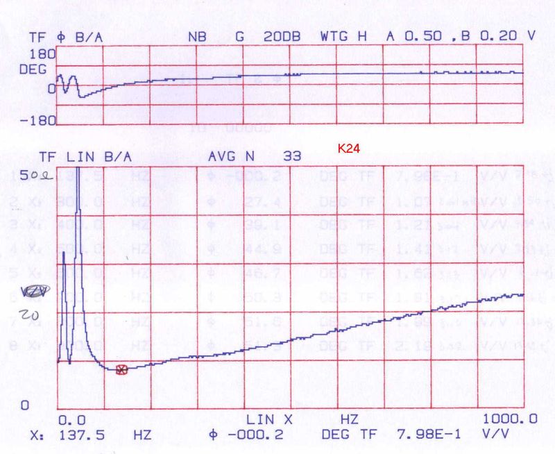
I tend to doubt that the crossover is causing anything like that. I am thinking that any peak in the impedance around 35 Hz would be the resonance of the woofer driver. I see peaks like that on every speaker I have tested. In fact, there are usually two peaks. I have never run test on a B&W though. Here's a Zo plot on a K24 in a ported box. It has two peaks around that frequency Al K.

-
Guys, This a very interesting point. It would not be difficult to test this out. I have all the equipment needed to do it. Lee does too. I suggest running a frequency repose plot from a good solid state amp on some speaker as a reference, then connecting a resistor between the amp and the speaker and running the plot again. You could start with your 3 Ohm example. Below is a complex Zo plot of the an actual AA network. The network is designed to reduce the level to the squawker but the nearly 30 Ohm peak in the middle of the midrange would seem to yield excessive attenuation considering the transformer used to do it is also yielding 3 dB of attenuation due to its turns ratio. My Universal network provides a flat 6-8 Ohm resistive load to the amp and the usual transformer setting is 5.5 dB. That's only a 2.5 dB difference. Power into 30 Ohms = 2.83 * 2.83 / 30 = 0.27W Power into 7 Ohms = 2.83 * 2.83 / 7 = 1.14W db = 10 * log10(1.14 / 0.27) = 6.26 dB Add in the transform ratio and you get 9.26 dB. I don't think that is really what is happening especially considering the actual Zo is more like 28 ohms than 30 Ohms. BTW: Several years ago I had Dean Wescott (DEANG) connect a resistor in series with his amp and his Khorn (AK-4 network) to test out a theory I had about the AK-4 at the time. I asked him to listen to it. His conclusion was that is didn't sound very good! Al K.
-
Lee, Interesting info. I'm curios about what you think of a constant current source with respect to "damping factor". A constant current source is an infinite Zo. No damping at all! It would seem a speaker would ring like a Christmas bell. Try tapping the cone of a cheap loudspeaker, then short the terminals and tap it again. The difference is dramatic! Al K.
-
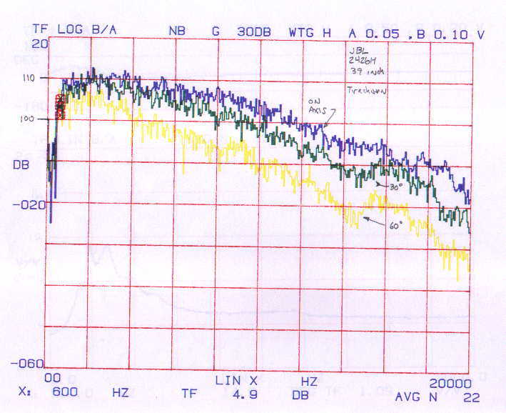
Here is an example of the “sensitivity” method. It’s a study of a JBL 2426H driver on a wood Trachrix horn. It’s old, so it was done on my older analyzer (Spectral dynamics SD375) using the voltage divider on channel “A” from the amp. Notice the analyzer identifies the scale as +20 to -60 dB and the display is “TF LOG B/A”. TF stands for Transfer Function. Note that the 0 dB point is actually 100 dB SPL at 1 meter (39 Inches). The sensitivity is about 108 dB on axis below 6KHz where I am using it as a squawker. That driver needs some major EQ-ing to compensate for the mass roll-off if you wanted to use it in a 2-way system. BTW: I did that for a while and it sounded quite good. Al K.
-
Radiogram, You are right on again! There are actually two measures of speaker efficiency. The one to consider is "sensitivity". It assumes 1 W in 8 Ohms which is 2.83V applied. This is the one to consider. You simply measure the output of the speaker at 1 meter with 2.83 V applied and to heck with the actual power delivered by the amp. No speaker is a constant 8 Ohm load. The Khorn with the AA network actually looks like 30 Ohms at 2 KHz! Sensitivity is actually a fixed ratio input to output. With this method, the Khorn is actually about 99 to 100 dB SPL at 1 meter sensitivity. I have measured several of them using a 2-channel analyzer (HP 3563a) with a calibrated mike on one channel and an voltage divider from the amp output to the other channel. The voltage divider is set to cut 2.83 V down to EXACTLY the level the mike produces at 100 dB SPL. This way, with the analyzer set to compare channels (transfer function) 100 dB SPL at the mike is displayed as 0 dB on the display no matter what voltage is being applied to the speaker. I can measure absolute sensitivity without having to wear ear plugs! Remember too that sensitivity is an average over the frequency rage involved. The level will be about 100 dB +- 5 dB or so. AL K.
-
66hr, I wouldn't worry about that junk. Weird stuff like that happens once in a while. Just blame it on Bill Gates and move on to the next disaster! Al k.
-
Crossover Frequecy Specifications - Confusion
Al Klappenberger replied to radiogram's topic in Technical/Restorations
radiogram, BTW Mike is correct in what he said. I think .9V represents .92 dB loss. That is actually better than what I expected. You didn't say what network you had. The AA will show loss around 2 dB because it's an old constant K design working in a singly terminated environment plus a few other problems with it. The later networks have a singly terminated filter having a single finite transmission zero. It's a better filter. That is probably what you have. It has less loss. Older networks usually have dried out caps that increase loss also. Al K. -
Nico, Yes, the A will sound more open at low levels. It's artificial ambiance caused by major driver overlap. It's what I liken to singing in the shower. It sounds nice, but it WRONG! It will also resolve into distortion when you raise the volume. It sounded laid back because you probably had the squawker level set back to compensate for the bad k400 horn. The A network is fixed at 4-0 on the transformer. That is right in your face! Al K.
-
Question from new italian member
Al Klappenberger replied to omero's topic in Technical/Restorations
Omero, First point: You shouldn't hang the squawker horn up like that! Those horns depend on the front mounting flange to damp the ringing. You need to mount it! Try taping it with a metal object. It will ring like a bell! As to the tweeter, I will bet the one you are using is better than the T35 or it IS a T35. If it says K77M or K79 keep using it! You can use a transformer if you want to try it. Set it to 3 dB (1.4:1 turns ratio) step UP. I suspect it will be the same as what you already have. Al K. -
I just talked to Dean on the phone. He thought taps 0 and 2 were both connected to ground. That would be a huge no-no! We agree that everything is ok for a 4 - 0 setting. It's just stuck at that setting as it's wired. Al k.
-
Dean, It's hard to tell for sure since the pictures are out of focus, but it looks like the transformer is a T2A. The output is taken from taps 4 - 0. In that case there really isn't any need to float the squawker driver. If you wanted to attenuate the squawker to setting 2 - 5 (0.8 dB more). I personally think 4 - 0 is to hot . Al K.
-
Nico, I suggest that you wait a while before getting rid of my Universal networks. I think you are going to find out the "jumping around the room" is not such a good thing after you listen for a while. I think this is first a impression after ridding yourself of the harsh K400 horn in favor of something better. Before, the network was helping the problem and you have discovered first hand what I always tell people, that is that changing out the horn is a much bigger improvement then the network.The artificial ambiance casued by the huge driver overlap of the A network is confusing you. Give it a couple weeks before you make a final decision. You may discover the Universal network can do more for you than just partly compensate for a bad horn. Al K.
-
66hr, The post looks good to me to spite all the gibborish on the top! How did you manage that? Al K.
-
Crossover Frequecy Specifications - Confusion
Al Klappenberger replied to radiogram's topic in Technical/Restorations
Radiogram, You are thinking like someone who understands filters to some degree! The fact is, the Klipsch networks are so goofy that none of the classic thinking you are using is applicable. This is the reason for your confusion. In a true contiguous "multiplexer" the lossless 3 dB points should be the crossover for constant impedance but if the network depends on the squawker driver pooping out, and there is no actual filter in the network doing the crossing over, the only way to define it is by the acoustic outputs of the drivers! Another factor is that the electrical cross should be the 6 dB points for best summation. I think this is part of what's called Linkiwitz-Riley alignment. The fact is that component loss add to the 3 dB point of a lossless network which causes it to approach 6 dB, especially in a woofer / squawker crossovers. If the crossover loss in the network is exactly 3 dB you will get a slight rise in output at the crossover assuming the two are in phase. They probably will not be though. This is true on a properly designed network, but not the Klipsch networks. I suggest that you stop trying to figure out the Klipsch networks. I have been doing computer analysis on them for years and they are all over the place! If you are interested in the actual response of a specific network, I can post the computer analysis on it for you. I have most of them on my computer as design files. Al K. -
Mark, On the bass thing, the tightest bass you can get is NO INDUCTOR AT ALL! That is what the AB network in the Belle used. I have never heard anyone rave about the bass with that network! Again, I am only one set of ears. I limit myself to instrument measurements. The only time I will say how something sounds is if it knocks my socks off, like getting rid of the K400 / K500 midrange horns did. Changes more subtle than that requires A/B comparison in real time to satisfy me. That is not easy to do. Even then, just because I might hear a difference it just brings up the next question, which is actually better? Since I seldom have a chance to listen to live music, I am no judge of what is better or worse. Al K.
-
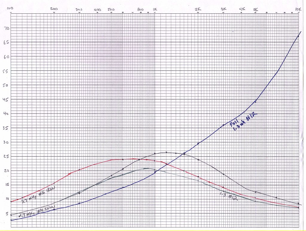
Here's another set of curves for woofer inductors. This time I kept the data and know what the coils were. It compares a 2.7 Mhy #14 soild wire, a 1.3 mHy #12 soild wire, a 3.7 mHy #16 iron core and a #12 foil inductor. Again, the foil inductor has its best Q FAR beyond the frequency range of the woofer! At 400 - 500 Hz the best Q is the Iron core. The foil inductor comes in dead LAST! Iron core coils have a nasty habit of changing their inductance with the amount of current through them. This makes a slight bit of distortion, so the air core is best if you have the physical room and can stand the high DCR they stick you with. Al K.
-
Herb, Interesting you should bring up foil inductors. I did a comparison of 4 inductors a few years ago. Here's the plots. It compares the "Q" (X/R) of a foil inductor, a Litz and two solid wire inductors. I don't remember the details about each inductor. I think the two solid wire were of two different wire gauges. It was two long ago to remember for sure. The thing to notice is the inductor with the highest Q at the 6000 Hz crossover (where it counts) is the Litz. The foil has fabulous Q but its at 50 KHz where it's of no use at all! It's Q is HALF that if the Litz inductor at 6000 Hz and only slightly better than the solid wire inductor! Foil inductors are very expensive making them a poor choice. Here again, how they sound may be a different story, but we come back to all the subjective factors I just don't want to deal with! Al K.
-
Like I said, it will be just one opinion, but I would like to know what you hear when you change out the inductors. Enough opinions from enough people and you can eventually come to a consensus. The comment about the gentle-slope networks "opening up" at lower levels then the ES networks is one of those reactions I hear over and over. When I can put a bit of science to it, I start to believe it might be true! Here's a little dig: The Bose 901 has a bunch of drivers all interfering with one another as they all make the same sound. It should have all sorts of ambiance at low levels! [] Al K.
-
The discussion of which cap sounds best is one that never seems to end! The measurement aspect comes down to what to measure. All I can measure is capacity and loss (uFd and D or Q). The listening thing still boils down to subjective comparison. There is just too much psychology involved with that. It takes a group of people in a double-blind test and then let the group vote on which sounds best. I betcha the results won't be unanimous either! I have just decided to use Sonicaps in the direct signal path in the high-end networks and Solen Fast-Caps in the woofer and shunt positions. That caps in woofer filters are so large and expensive from the fancy brands that I just can't use them there. You just can't buy the 91 uF cap I need in the ES400 in a Sonicap! I an iron-core inductor has a measurable amount more distortion than an air-core inductor in a woofer filter, but again the price gets in the way. So does DCR with the air-core. Everything in engineering is a balance of compromises! AL K.