Erik Mandaville
-
Posts
4571 -
Joined
-
Last visited
Content Type
Forums
Events
Gallery
Everything posted by Erik Mandaville
-
"Dean, You shouldn't need any autoformers." That's an accurate assessment. An autoformer is simply a way of balancing driver outputs. The majority of crossover networks use L-pads consisting of either a single series (as in on network design that was posted for the Jubilee), or one in series and another in parallel to maintain the original impedance of the driver being attenuated. The autoformer can also be replaced by resistors on ANY of the older networks, however that makes them less like the original design. Mr. Klipsch preferred the autoformer; other equally well-known companies used and continue to use resistors. Both work. Since there is no autoformer on the new Klipsch Heritage networks I've seen, I was wondering why they are no longer in the picture. Possibly for a reduction in cost, etc. I suspect only Klipsch knows the answer to that, which is absolutely fine. I'm confident in their engineering. Erik
-
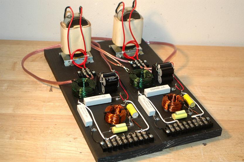
Gee, Mike, Is that what those are called? I would say that's obvious enough -- the reason I mentioned the luxury of being able to make changes and adjustments. I have a couple of them, too. Actually, more than a couple of them. What's shown above isn't a finished product. From doing this a long time myself, I understand and appreciate the developmental stages, and what it takes to get there. Cheers! Erik
-
Those boards on top of the Crown look nice -- good work. It's nice to have the convenience of ample room to work with. That's a luxury I haven't always been able to enjoy. It sure helps to be able to make changes and adjustments. Erik
-
I want to upgrade my La Scala's Tweeters
Erik Mandaville replied to maxdblsbb's topic in Technical/Restorations
Bob's tweeters were a great upgrade for us, and really made the K-77s sound a little dull. I'm not talking about extracting every microscopic detail, which to me isn't musical, but rather just being able to hear some cleanly reproduced 'highs' and extension. Very easy to replace, with the added advantage of a lower crossover point. For me, that's 4kHz rather than 6k. I'll let others talk about how to get to the lower crossover point, though! I agree that the cap replacement doesn't result in new technology per se' but just making sure the crossovers are using the correct capacitance, with possibly improved electrical characteristics (ESR being among those). You might just try a capacitor replacement first, which isn't very difficult, and go from there. If you do to many things at one time, at least in my experience, it can be hard to know what's changed (if anything) and what was responsible for the change. Also: despite what you might hear to the contrary, more expensive capacitors may NOT equate with a proportional increase in improvement. Over the past 18 years of doing this, there are times when I have found the less expensive part to be the one that gave me what I was looking for. Have fun! Erik -
lets see YOUR two channel setups
Erik Mandaville replied to crazytubepower's topic in 2-Channel Home Audio
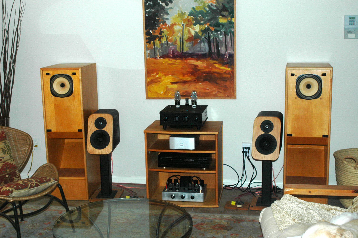
Jim: Thanks. We really have two systems -- one upstairs that's used for both HT and music, and our downstairs systems seen above. We adopted a young female Akita last year that is handicapped and has quite a difficult time with stairs. When we first got her, she was barely able to stand on her legs, and with tons of love and teaching, she can now run (bounce is more like it!) and play with her siblings. We also taught her how to climb upstairs, but because of this we are spending a little more time downstairs than we used to. The Lowthers used to be the side channels in a 7.1 systems, which has been changed to a more conventional HT with five speakers plus sub. These speakers sound so spooky real with the Moth amp, that I thought it would be kind of a shame if not a waste, to not use them together in a dedicated system. The two way monitors do sound great, like many decent two-ways often do, but for the size of the room, they are just a little on the small side. The Lowthers load the room so well, even at moderate volume levels, so I'm going to probably move them up into my work room, where my drums are now too. I turned that into a very nice space, and both the radio your dad built for me, as well as the SS version my dad sent me for Christmas last year, are in there next to my work bench. Tons of fun! Bruce: I understand the time for mods thing. What's nice about the grid choke is that it's literally about 30 minutes/amp. Once the holes are made, even less than that to take out the grid leak resistor and put the choke in. Still, it just takes time to unplug everything, take the bottoms off, and all of that; and when tired from the week, so much nicer to just sit down to enjoy some music. The Moondogs are also great amps just the way they are. Cool Seth Thomas clock! Erik -
I imagine the bass capability of the amps below would be quite good, and not only because of their horse power. There are factors other than output wattage associated with strong and controlled bass response. Evhttp://www.transcendentsound.com/BeastOTL.htmen the SE OTL from Transcendent sound, with power comparable to a 45 triode, had outstanding bass ability from such a small (in terms of power) amplifier. The Transcendent Amps I have been lucky enough to have here have consistently provided some of the very best tube amplification we have heard. Having built them, they are designed and put together uncommonly well, IMO, for the cost/performance ratio. One of these days we'll have something like them for our own system. Bruce Rozenblit is a very talented designer, and is also one who has -- rather bravely, IMO -- made his circuits available to the public. If you like to look at lots of tubes, which has nothing to do with the design behind these amps, OTLs will be an advantage in that respect. Even the T-16 stereo amplifier with its more modest output was a stunningly good amp. I had the chance for one, and I kick myself for not taking the plunge. Amazing sound, very strong, tight bass response. http://www.transcendentsound.com/BeastOTL.htm Erik
-
lets see YOUR two channel setups
Erik Mandaville replied to crazytubepower's topic in 2-Channel Home Audio
Bruce: Again, very nice environment for listening and spending time. Perhaps I'll here about some Moondog changes -- grid choke or ultrapath -- in the future, perhaps not. Glad I could send those your way, and at the time it was nice to discuss those with you. Regards, Erik -
Best speaker tap to use on a McIntosh with Quartets?
Erik Mandaville replied to reynoldslaw's topic in Technical/Restorations
Here is some more information -- including the desired math: http://www.transcendentsound.com/amplifier_output_impedance.htm Erik -
And speaking of resistors, I wonder that Klipsch may one day decide to include optional (switched) steps of attenuation for the new Heritage line. I've done it using the autoformer, and many companies do that with tweeters and midranges, including fixed L-pads. Having to take a network out of an enclosure to unsolder and resolder connections is a pain. A three position switch would do the trick. History has shown that there are differences of preference concerning this aspect of the speakers. Some built-in user-friendly flexibility would be helpful I think. Erik
-
Why did Klipsch stop using the autoformer? Erik
-
lets see YOUR two channel setups
Erik Mandaville replied to crazytubepower's topic in 2-Channel Home Audio
Oh: The ceramic two-way inclosures were cut from a single long piece of red flue tile. I used a circular saw with a masonry blade, cutting at 1/8" depth passes at a time, all the way around, until I cut through. The blade angle at the top and bottom had to be changed to account for the slope, which was not so fun to work with. I welded the 15" stands together from 1/8" rectangular box steel, which is filled with a heavy, ceramic aggregate material I used when making clay for my college students. Erik -
lets see YOUR two channel setups
Erik Mandaville replied to crazytubepower's topic in 2-Channel Home Audio
Bruce: I really like that space -- warmth of wood, a mantle clock (do you know the maker? do you guys use it?), books -- it must be a great place to sit and listen, or just to think, with the tick-tock of the clock movement in the background. I have too many old clocks, but I love every one of them. Here is our two:channel setup, which will change as far as sources go when we get an HD radio and eventually a new CD player. We'll probably move the Denon multi-format player down from the HT setup, and purchase a higher resolution player for movies. Upstairs is all Klipsch Heritage as far as speakers and center channel: Lowthers in rear loaded horns right and left, with a sloped-baffle-time-aligned pair of monitors between them. They're made from very thick and virtually completely inert ceramic flue tile (high aggregate which does not ring in the least -- knuckle wrap is the same as thumping a tree trunk). The drivers are made by Vifa, they're ported at the back, and the crossovers are on the floor. I had been using a high-order series network, but have been playing around with a much more simple parallel network. I had been using more expensive capacitors in the tweeter, and much preferred the less expensive mylars. Caps just aren't a big deal to me -- I use what sounds good regardless of measured response. The Moth with AVVT meshplates (rather expensive) (like the pair my wife and I gave to another forum member awhile back), and the digital Teac for the two-way monitors, which is being used with my 6SN7 preamp. I'm just using a Y-jack off the CD player -- one pair to the Moth, one to the preamp. I was also using the stepped attenuator I built from a Transcendent kit in the moth, but found a simple pair of Alps mono log pots better for balancing with differences in tube gain. Bass response with the PM2A Lowthers is not really deep, but what you do get sounds marvelous, and is actually pretty respectable. I think I may be moving the smaller monitor/Teac system to another room, since my wife gets confused about what is what when she wants to listen when I'm not at home. Erik
-
Inductors for Heresy I's tweeter & squawker?
Erik Mandaville replied to kg4guy's topic in Technical/Restorations
Sounds great! I hope it works out for you, Erik -
Inductors for Heresy I's tweeter & squawker?
Erik Mandaville replied to kg4guy's topic in Technical/Restorations
kg4: The above filling is something I tried in a very early pair of Heresies we own. That cabinet is really rather smaller, particularly in front-to-back depth, than the more common model I and II versions. I both lined the walls, and lightly filled the inside, and it helped. It was just 'tacked' in temporarily to try it out, but it's in the enclosures for good. This model Heresy, as well as Model Is seem to not use a gasket between the back panel and the surface to which they are screwed against, and I have wondered it this was done intentional as a way of providing a mild resistive vent effect, as a way of slightly increasing efficiency -- sometimes referred to as 'aperiodic enclosures.' They use a filled or damped port, which results in a sort of combination of the benefits of both vented and and sealed designs. Dynaudio used to sell add-on damped ports like this (I think I used to see them in the paperback Madisound catalog I had years and years ago). Maybe they still sell them. DIY versions consist of a small port cut in the cab, with something like 1/2" wire fabric on either side which holds the damping matrial in place. Anyway, the point is that some internal acoustic treatment and stuffing might really help your situation -- if you haven't already tried it. Erik -
Inductors for Heresy I's tweeter & squawker?
Erik Mandaville replied to kg4guy's topic in Technical/Restorations
Sure - Hey, you may have already done this with your woofer cabinet, but some soft 'Acoustastuf' or poly fiber filling might be something worth trying. It can provide very real (meaning 'obvious') increases in efficiency, and this might help if your thinking bass efficiency or output could use a little help. Not sure if you're using a vented/ported reflex enclosure or a sealed one, but the way those are treated in terms of fill, varies. I used to use long-fiber natural wool, which worked really well, but tended to settle with time rather than stay fluffed up within the enclosure. Acoustic foam on the back and other walls might work well, too. To try either, you can go to those sort of home craft stores, which would have this stuff (cheap pun) in the sewing, fabric, etc. dept. Erik -
Inductors for Heresy I's tweeter & squawker?
Erik Mandaville replied to kg4guy's topic in Technical/Restorations
Lastly this evening: If you have access to test data for your woofer (can't remember which one you're using, and I'm too tired to go back up to check), but you might see if their is an impedance curve available for it. If there is a rise in impedance, you can use a formula to design and impedance equalizer which may offer an improvement over what you have right now. Or maybe not. You need to know a couple of values related to the voice coil, which is often published by the manufacturer. Once you have those, the formula is easy, and the installation of the needed parts just as easy (you already know how to solder, after all!). I think I even found an on-line calculator for this, and beyond that you punch in a couple of numbers and let the computer do the rest. A snap. Piece of cake, even! Erik -
Inductors for Heresy I's tweeter & squawker?
Erik Mandaville replied to kg4guy's topic in Technical/Restorations
For Illustration purposes: This is what a more conventional 1st order 3 way network looks like: There is a single series capacitor on the tweeter, the value of which is determined by the impedance of the driver and the desired crossover frequency. Incredibly simple. The network for the squawker is called a 'band pass' (some refer to it as the pass band), the series capacitor and inductor values are determined again by the impedance of the driver and the upper and lower limit crossover points. And there is the single series inductor on the woofer. So again, extreme simplicity. I've said many times that it's the simplicity of networks such as the E and the A that make a direct translation to a true band pass much more straightforward. These earlier networks did not include other compensation networks like notch filters, impedance equalizers, etc., and we generally know the behavior of the drivers in question (if they are the original Klipsch drivers). The actual values you would need for part of the bandpass and the woofer inductor would be not far from what is shown, however I'm not familiar with the test performance of the woofer you're using. It may be that your woofer could benefit from a circuit that would boost its lower bass response, which consists of an inductor and resistor in parallel with one another and in series with the load. I'm so used to getting this information from tables and charts in books I have, but this makes it easier. I've found some calculators that I prefer over others, but this gives you an idea. Note: There is NO attenuation in the crossover shown. You can calculate the desired reduction a couple of different ways, but also use a variable L-pad on both tweeter and squawker to find the exact volume you want. It does not matter to me in the slightest whether you prefer an autoformer or single or pair of resistors -- I have my own interests and preferences. I'm showing what would be needed to do this without the autoformer, which my preference (my own tastes derived from my own experiments). You can see, though, that the connections are no more difficult than the autoformer, and no guess-work about what tap is going to do to the reflected impedance (which is an important part of calculating the needed values of capacitance and inductance. Have a look for interest's sake -- just remember that your crossover point is not 750Hz, but 700 (at least that's what I remember as far as the type E). Erik Well -- I just tried to post this schematic and it didn't work. I have to write a test for my students right now but I can draw the thing out of my head later when I have time. Apologies...... edit: Bob, who already posted above, created a modification for the type A and AA that uses a lower crossover point using his new tweeters. It incorporates the use of an inductor in series with the squawker after the autoformer (since you did ask about that), as well as a change in capacitor value, and I don't know whether he has done the same for the type E you're using. I use an even lower crossover point on my Klipschorns, but I also don't use the autoformer. I prefer the use of resistors, so I'm going to defer modifications to autoformer networks to them. It's not too different, really, as long as one is keeping track of the numbers that come into play with different tap settings. -
Inductors for Heresy I's tweeter & squawker?
Erik Mandaville replied to kg4guy's topic in Technical/Restorations
They are examples of different networks used for 'very known' drivers. They were intended to show possibilities of attenuation for the midrange based on both the autoformer and more common resistive L-pad. I wanted to show both fixed and variable versions of both. The inductors you use depends on a number of things, but I'm hoping some others might offer their help, as well. Inductors are not necessarily what you may be looking for. As a matter of fact, there are some schools of thought that would suggest that more inductors in a crossover are a compromise. Yet others will maintain that their sonic benefit is without question, and strive to design the higher order networks that require them. There are always different sides to a story. My feeling is that you MAY have a perfectly good woofer, but need to balance it with the other drivers. You don't necessarily need more inductors to do that; and depending on what amplifier/s you're using, it might be a better choice to try to attenuate the HF and midrange first without adding extra parts to your crossover. Some here are very familiar with the type E network, and might be able to help with what would be needed to attenuate both the tweeter and squawker to your liking. If the T2A autoformer does not have quite the right level that you think you need, there is another autoformer available that should. Before you start adding inductors and changing the order of your existing networks, I would work with what's available to you right now. Good luck! Erik -
Inductors for Heresy I's tweeter & squawker?
Erik Mandaville replied to kg4guy's topic in Technical/Restorations
And last idea experiment for attenuation: I was interested in working out a system that made use of the autoformer, but where one could toggle back and forth (by way of an external switch) between different taps on the autoformer. This one simply jumps between three autoformer settings, which I wanted to try without the simultaneous change in value of the input capacitor. It worked fine, and I did not notice any anomoly in performance other than the difference in attenuation of the driver. Again, one could use a swamping resistor to swamp the impedance so that capacitor values can remain the same. If one didn't want to use the resistor for whatever reason (I know some of the reasons), it's not difficult to include the change in value of capacitance, as well. One would just need the required number of caps to correspond with the number of switch positions. You choose the one you like best. Erik edit (apologies) well, okay. this is the type A, plus Bob's little inductor, plus swamping resistor. Anyway, you get the idea. There is a little switch box seen that I just put on top of the cabinet to experiment. I tried the same thing on a standard type A for the 6kHz crossover and without a swamping resistor. Swamping resistors have been around forever, by the way. I even used them on the Lowthers, which don't use a crossover. I'm glad I can type quickly! Anyway, this is to show that there are possibilities regardless of method of attenuation (autoformer or fixed or variable resistive L-pad) They both do the same thing, though go about it differently. 3dB down is 3dB down regardless of chosen weapon -- at least that was the case for me. Some prefer to do that by heating a resistor, others by presenting a slightly annoying impedance match for the amplifier used. In the end, we really have the capacity to choose what we like best -- as with any aspect of this hobby and its chosen components.
-
Inductors for Heresy I's tweeter & squawker?
Erik Mandaville replied to kg4guy's topic in Technical/Restorations
Oops -- sorry, that was the breadboard design for the first one I posted. This is where it started out, and I got really excited about how it sounded and fine tuned values a bit from there. This should be the one with the variable L-pad (at least I still think I have that picture) edit: The network to the left is the type A . Erik
-
Inductors for Heresy I's tweeter & squawker?
Erik Mandaville replied to kg4guy's topic in Technical/Restorations
Image above shows an autoformerless approach using fixed resistor-based attenuation. This is the mixed-order network I built for my Klipschorns with home-made coils (which I could wind for the EXACT amount of inductance I wanted -- since the precise calculated value isn't available). I know of others who solve that problem simply by buying a larger value, and then unwinding it as needed to achieve the inductance they want. The network above uses a 4000Hz crossover point for the tweeter at a slope of 18dB/octave, a very focused band-pass on the squawker, and a simple but very robust choke in series with the woofer. This next one shows what a variable L-pad looks like. It's a network that in design is much like the ALK Universal (I built it with parts I had on hand as an experiment), but uses the variable 50 Watt L-pad shown with a black knob. I tried this with an extremely low powered output-transformerless amplifier, and the results were terrible. With a more powerful amplifier, it was much much better. The crossover point in this one is 6kHz. Just to show you some alternatives. Since this type of control maintains the impedance of the driver (16 ohms) that's the value of impedance that's used in calculating the capacitance needed at the chosen crossover frequency. In other words, no need to change caps when all you want to do is turn down the volume on the squawker.
-
Inductors for Heresy I's tweeter & squawker?
Erik Mandaville replied to kg4guy's topic in Technical/Restorations
Kg: It may be that you have a very good performing woofer, but, again, just need to match the outputs of the other drivers (the job of the autoformer on the old Klipsch networks). The loudspeakers you made should still be quite efficient, even if you have to drop the tweeter and midrange outputs again. The nature of the autoformer makes quick attenuation difficult, but it can be done. A mixed order network can sometimes even make a difference, but you have to do a little work for that. The kind of network you have is simple in that there aren't added elements such as impedance equalizers, notch filters, and so forth. In other words, the network is designed around the impedance of the drivers, the desired crossover frequency, and the amount of attenuation (which, considering how the autoformer works, also influences the refleced impedance) -- only. Still very simple. Thus, if you are using a single inductor in series with the woofer, using a slightly higher order network in the tweeter and midrange branches may offer slightly higher insertion loss, which may provide the balance you are looking for, which offering some of the subjective benefits of a sharper cutoff. And this brings us back to your original question about the addition of inductors in the tweeter and squawker. It's the same idea I used in building my own new networks for Klipschorns. But absolutely try another woofer. If you can find something to balance out the system that way, it will be easier for you. However, if all you need is a tiny bit more attenuation in the tweeter and midrange, Bob offers an autoformer with finer steps of attenuation than the T2A. You just have to keep in mind that changes in steps of attenuation on the autoformer alter the previous balance of reflected impedance. A swamping resistor can be used so that tap changes can take place without changes to values in capacitance, but whether you like what that does is something you would have to try. Still another method: Design a crossover for the ACTUAL impedances of the tweeter and midrange (such as a 12 or 18dB/octave), and use a variable L-pad (like the old Altecs and others) to balance the drivers. An L-pad is not technically part of the crossover, but rather a means to balance the drivers. You would read in many books that the L-pad (whether variable or fixed) should be installed AFTER the crossover. It's just a volume control that maintains the impedance of the driver regardless of amount of attenuation. Since the impedance is maintained constantly, there is no need to change the amount of capacitive reactance you need for the desired crossover frequency. You just turn the drivers down so they match each other and the woofer. Or again, find a woofer you like better -- whichever you prefer.....and have fun. Erik
-
Good! It might be a great opportunity to learn something valuable from someone with considerable experience. Lots of people like Bose products; Lots of people don't. Same is true for many audio component companies. I've been asked by people how I can stand the sound of speakers that were designed for auditorium and PA use (HARSH). We know that's only part of the story..... Have a good time, Erik
-
Inductors for Heresy I's tweeter & squawker?
Erik Mandaville replied to kg4guy's topic in Technical/Restorations
Sure. The setup you've created looks really interesting, by the way. I totally understand about not wanting to mess around with something more once it sounds right. The top end is really the critical part, and hopefully you'll find the best way to balance everything out. Nice work -- I've always thought the form-follows-function, sort of utilitarian-tech of uncovered (sans grille) drivers in simple boxes or unfinished MDF to be visually appealing. Nice veneer can be good too, but I think it's just sort of interesting sometimes to consider performance only. I've heard great sounding amplifiers installed in aluminum baking pans. Erik -
Inductors for Heresy I's tweeter & squawker?
Erik Mandaville replied to kg4guy's topic in Technical/Restorations
Good job on figuring out how to wire those on your own. If you like, you can also find solder terminal lugs, or lugs that have eyelets (sometimes used for solder connections on barrier strips) that can be mounted to the board so that the leads from caps and so forth can have a more secure place to connect. Sometimes it's necessary to pad more efficient tweeters and midranges so that their output matches more suitably to that of the woofer. Erik