

John Warren
-
Posts
2263 -
Joined
-
Last visited
-
Days Won
1
Content Type
Forums
Events
Gallery
Posts posted by John Warren
-
-
On 1/9/2021 at 5:19 PM, J.F.Blotz said:
Yes, Rich
The Music Box was located at 58 Central St. in Wellesley.
I worked there with Bill Bell for 21 years. If you , or anyone have any questions please let me know.
Purchased a few items there including a pair of decorator Klipschorns.
Great times, long, long ago.
-
 1
1
-
-
Electrolytics age while under load. The life expectancy of an electrolytic (say 4000h) is based on it operating typically at 2x its max. continuous ripple current and max temperature (usually 105C). Temperature is the big driver. Most electrolytics are rated to 105C max (220F) which is quite hot and sitting at that temperature with no power will shorten life.
In real world circuits, electrolytics rarely exceed 40C and, at design ripple current, will last much, much longer.
-
1
-
-
Why is this topic in solid state?
-
3 hours ago, mark1101 said:
Your HH Scott 299C / LK-72 unit for sale appears to be an awesome recreation of that unit. The finished product and the test data you present are very impressive. Someone will enjoy that for a long time.
Thank you! I made four amps and sold three. It would be good if it had a wood-grained base that would make it aesthetically pleasing. Might make it easier to sell too. I can fabricate one if necessary.
-
1
-
-
Good to hear!
I took a year or so off servicing the old McIntosh hardware, tube and solid state to focus on the day job (which is also more engineering). In my little world, getting to a point where I'll soon retire from all day jobs to focus on other things (getting old!) and going into retirement spending time working audio hardware has lots of appeal. Good health into your 60s and 70s is the exception not to be taken for granted and extreme stress (like working in an engineering startup as a key contributor) debits health and beats up the immune system. Sure, you can eat right like low carb. exercise and maintain a 23 BMI but the termites and Maxwell Demons are always nearby.
The amp I'm working on in the link above was missing a few parts, the owner wants it restored to "like new" condition. I have some pretty scarce parts on hand including autotransfomers, power supply transformers, meters and even two 2100 stainless chassis, all in basically like new condition. I managed to obtain this hardware whilst working at a McIntosh service facility in the late 70s!!! There's also a method that allows the chassis to be polished to a mirror finish without taking the lettering off. It's a secret.
-
2
-
-
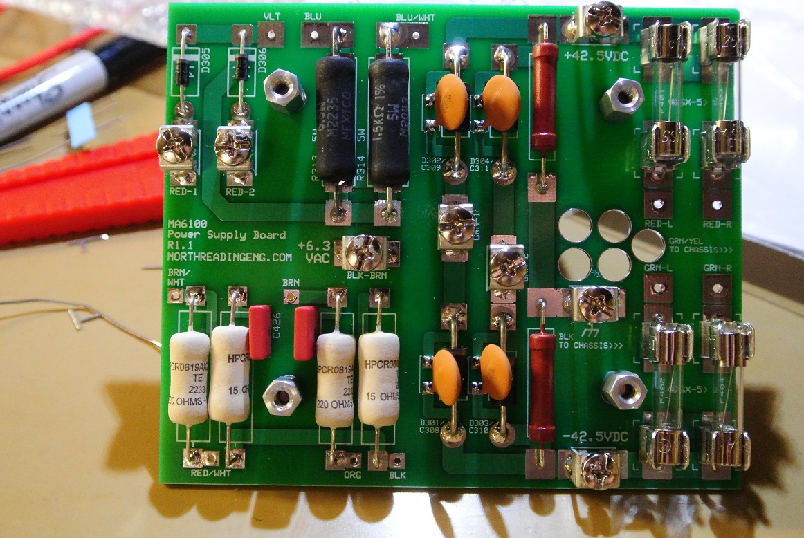
For those of you that have a distressed MC2100 or just want to spruce up the one you have, I've got one that's in need of repair and will document what's done to it here:
MC2100 restoration (northreadingeng.com)
Will provide part numbers of the hardware as I go.
-
6
-
-
18 minutes ago, Deang said:
The data sheet doesn’t say, but I think those might be polarized. OTOH, I haven’t had my sixth cup of coffee yet.They are. Is this a crossover application? Thought the OP was looking for an electrolytic for power supply application.
-
2 hours ago, Jhakobe said:
Much appreciated suggestion. I saw those and considered using…I opted against them due to the 20% tolerance.
What do you think are the typical tolerances for Al-electrolytics?
And, I suppose, if you really want something at or very near 25MF you could buy 100 of them and sort. You should find three or four around 24-26MF.
-
1
-
-
On 12/18/2022 at 7:55 AM, Jhakobe said:
I’m having trouble finding a decent radial 25uf capacitor (and a 20uf) to replace the old ones. Axial’s are available though.
Any insight greatly appreciated!
-
13 hours ago, boom3 said:
Signed up!
Excellent!
FWIW, I've added a few more boards but intend to keep the format simple. I've used Simple Machines Forum software. It's been around for some time, is powerful, open source and well maintained with regular patches and upgrades. There are two security questions to answer at registration (answers are not case sensitive and are: Binghamton, resistance) and an anti-spam visual verification image to decipher (the bots are pretty good at getting past those however). Might have to incorporate reCAPTCHA if the bots are too much, so we shall see.
-
On 11/5/2022 at 9:10 PM, henry4841 said:
CL-90 I hope is one of them since that is what I use.
I had a CL-90 as it turns out and effect is shown here:
-
 1
1
-
-
I've been a regular member on this forum for 22 years! I've posted a lot of stuff here.
That said, I've created a forum for experimentalist, builders and engineers. It's not linked to my webpage. It's for those that have interest in designing and building hardware. There's also Marketplace section where gear can be sold and a section where members can list parts and components they're looking to acquire. I have no interest in advertising on it, I have plenty of server capacity elsewhere for advertising. I'm interested in idea generation and exploring concepts. Manufacturers are welcome too but no advertisements.
Here's the link:
North Reading Engineering Forum - Index
Also, a few years back, I tried getting a forum up but had all sorts of issues with bots and attacks and decided to take it down. The forum software (SMF) I'm using now appears to be better configured to resist internet garbage. That remains to be seen.
jw
PS. I'll leave it up for a few months and contribute to it with projects I'm currently working on! If there's interest in the forum, I'll leave it up. Also, if there's interest in other topics then shoot me an email at
forum@northreadingeng.com
-
8
-
-
1 hour ago, henry4841 said:
When did McIntosh go with SS rectification in their tube amplifiers ?
Around 1960 give or take.
-
1
-
-
3 hours ago, Bubo said:
My EE Chip Designer Friend RIP who was way into Tubes at one point.
On his amps, he said the first hing he did was pull the rectifier tube, and stick two diodes into the sockets,
FWIW
A few of the McIntosh service shops were doing the same thing with tube amps that came in for work. The rectifier was pulled and replaced with a plug in. The rectifier tube was returned in a white box.
I know because I was a technician working on them back then (late 70s).
-
1
-
-
On 11/8/2022 at 6:27 AM, henry4841 said:
You are to be commended for doing real world test and not just simulations on some software which is what one mostly sees on forums these days.
Ok, here's a forum dedicated to this sort of thing.
I've put it on my site. I'll perform various amplifier, network or loudspeaker test if they provide value and are interesting (to me!). I have a well-equipped test bench/lab and can perform measurements in electrical and acoustical domains. Always looking to add capacity to the lab as well and, should a test require a special instrument or setup, will get it.
The link is below, no ads and guests can view attachments. If it becomes a bot magnet or just becomes a drag it'll go away.
https://www.northreadingeng.com/forum
-
2
-
-
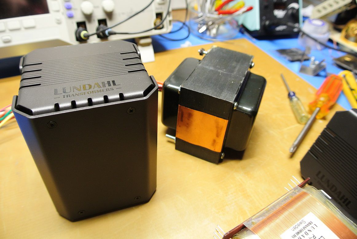
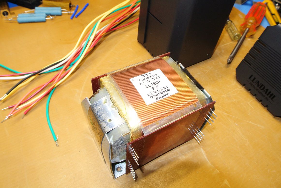
If you're so inclined, try a "different" output transformer configuration. For example, I have a customer that requested the 299C reproduction amplifier using the Lundahl C-core and based on my listening, sounded excellent. They're a bit pricey. The powder coated enclosure provides a nice aesthetic. A 299C power supply transformer (Heyboer wound) is shown next to the C-core.

-
1
-
-
On 11/8/2022 at 1:19 PM, captainbeefheart said:
First is these people doing these changes aren't going to step the voltage down on the primary. I see what you are trying to do which is create the same operating point for the circuit in order to compare just the rectifier and not the changes made to the operating conditions around the tube. E.g. higher plate voltage and current if bias isn't adjusted.
This leads to a completely new problem created by reducing the primary voltage so low. The tube heaters are now running low, for 117v to 6.3v secondary at 111v the heater will be now ~5.8v. This is most likely lowering emissions and subsequent transconductance of the devices.
I had considered this. I've been noodling selling a revised embodiment of this amplifier and, to know how it behaves over a range of operating conditions becomes an issue. The performance with a tube rectifier from 110 to 125VAC on the primary is largely unaffected based on what I've measured.
So, what's unaffected mean? Power v. %THD at 20, 500, 1,000, 5000, 10000Hz similar, FFT of components similar, sound same.
-
1
-
-
On 11/8/2022 at 6:27 AM, henry4841 said:
You are to be commended for doing real world test and not just simulations on some software which is what one mostly sees on forums these days.
Well thanks!
I have some experience with this topic and found the topic worth the effort.
-
On 11/5/2022 at 9:10 PM, henry4841 said:
CL-90 I hope is one of them since that is what I use.
I haven't gone thru my inventory but maybe. I'm noodling a good way to record the current v. time thru the power supply primary, tube heaters, etc. I have plenty of meters and can capture max values but would prefer to record the response differences in a plot. The sampling rate has to be high given trying to measure a transient and the resolution of the capture has to be a few mA both AC and DC.
-
1
-
-
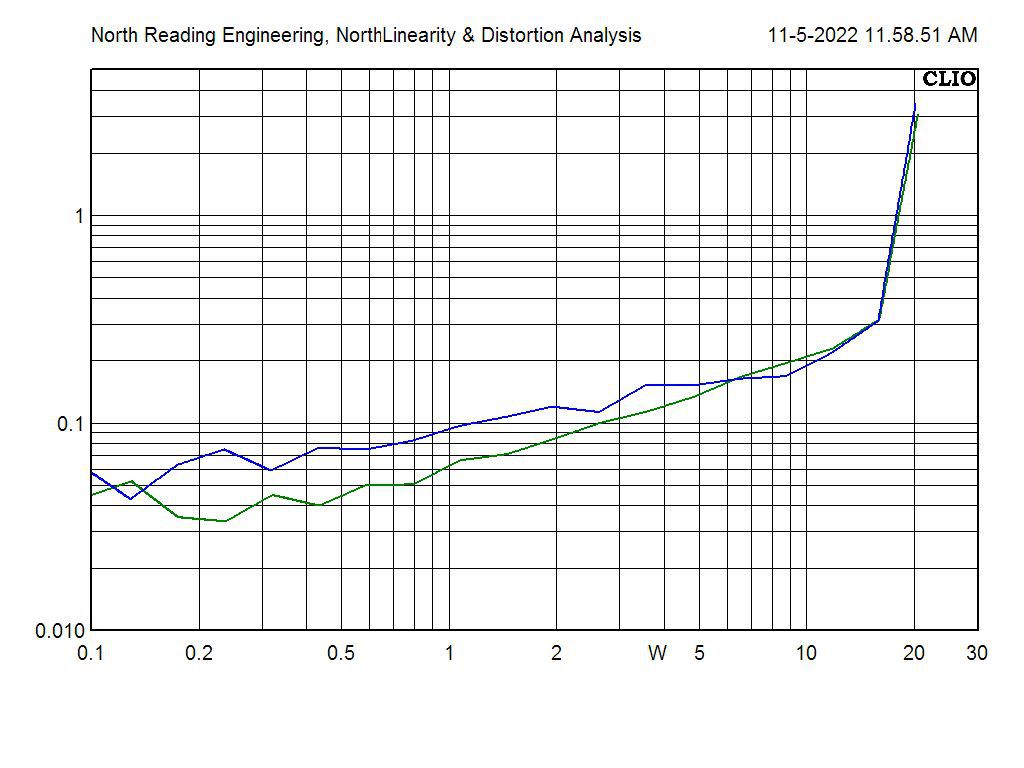
Data
Test case, one low-cost Chinese 5AR4 and a 2x1N5408 rectifier plugin. Amp is a 299C scratch clone I made last year. I laid the amp out on PC boards an assembled the entire unit on a CNC machined plate.
First test was to measure distortion at equivalent anode voltage, in this case 425 VDC.
With a Variac, the PS transformer primary VAC is adjusted to provide anode voltage at 425VDC for both rectifiers. %THD to full output power at 20Hz is then measured and compared. Load is a 50W non-inductive power resistor across the 8 Ohm output tube transformer secondary tap. 5 measurements for each rectifier were taken and compared. If the result was consistent between each, it's reported here.
At 117.1 VAC at the PS transformer primary the 5AR4 produces 425VDC with 1243mA at idle.
At 111.6 VAC at the PS transformer primary the 2x1N5408 plug-in produces 425VDC with 1245mA at idle.
Blue is 5AR4
Green is 2x1N5408 rectifier
A measurable difference below about 2W RMS, above that it's a wash. There are other tests that are worth performing but this was the quickest.
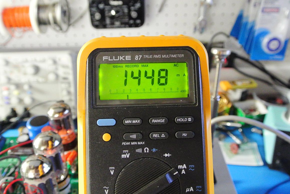
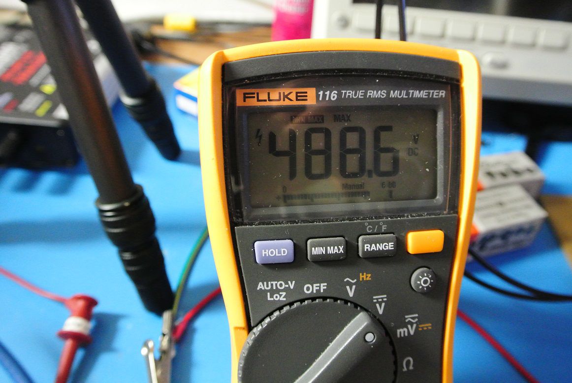
The next test was to fix the PS transformer primary voltage to 120 VAC for rectifier condition, turn the amp on and measure the PS transformer instantaneous (i.e., "turn on") current thru the AC power entry module. The peak VDC at the anode is also measured.
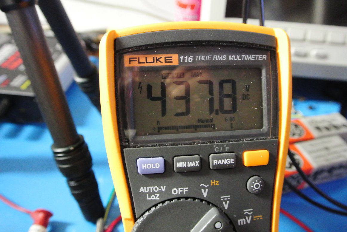
The 5AR4@120VAC peak current 1448mA AC and peak voltage 437.8 VDC
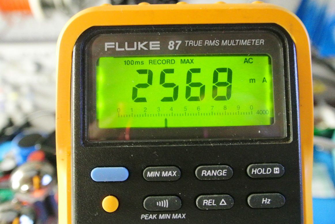
The 2x1N5408@120VAC peak current 2586mA AC and peak voltage 488.6VDC
The instantaneous current draw is 1.2A or about 2X greater using the solid-state rectifier. Peak anode voltage at turn-on is about 51VDC larger using the solid-state rectifier as well.
Note that wall power can approach 125VAC which would create larger differences in magnitude than what's being measured here.
Next will be filament current measurements at turn on and the effect of various in-rush current limiters on the solid-state rectifier turn on characteristics.
-
2
-
4
-
-
On 10/24/2022 at 1:19 PM, captainbeefheart said:
Can you elaborate?
I don't see how an in-rush current limiter is making the life of tubes any easier, well unless you mean the rectifier tube.
Before the days of the internet, I measured filament draw at start with tube, ss and ss + various in-rush limiters, AC, DC power on both a few preamp and power tubes. I don't have the data, so I'll have to replicate the measurements. Differences are significant.
-
On 10/24/2022 at 8:52 AM, tube fanatic said:
I can’t agree with this. The extra voltage on the tubes may exceed the rated limits and, in addition, could shift the operating point of the tubes resulting in different distortion characteristics which are not desirable.
Maynard
I'll get back to you on this.
-
If you want to hear an improvement swap the tube for a plug-in solid-state rectifier. Rail sag is, for all intents and purposes, eliminated. It's harder on the tubes but that's why we have in-rush current limiters.
-
2
-
-
3 hours ago, michaelwjones said:
So in your experience it takes only six months to design, build and begin manufacturing of a new tube line?
No, I don't expect a new tube line manufacturing tubes in 6 months. But I would expect some feedback by now, what are they doing? What's the down-select? What tube or tubes are planned? What's the date of first issue? What's the cost?
This isn't hard, J&J has already identified the popular tubes.

McIntosh MC2100 teardown/restoration
in Solid State
Posted
Nice of you to say, thank you!