


Edgar
-
Posts
2594 -
Joined
-
Last visited
-
Days Won
1
Content Type
Forums
Events
Gallery
Posts posted by Edgar
-
-
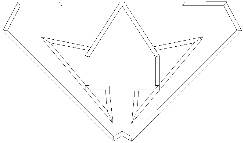
Here's another one. This one is 28½" from corner to face, so the 500 Hz Altec horns will fit.
Again, I'm just playing with my CAD program. I wouldn't dream of second-guessing Paul Klipsch or Roy Delgado. But I do like to think about what could be ...

-
Note the test performance differences in the paper!
The frequency response associated with Figures 4 and 6 is in Figure 5, not in Figure 9. Compare Figure 5 with Figure 8, and below 500 Hz they're pretty similar.
-
The 511A is 18½" deep but doesn't need a separate throat. Might work.How about a 511 horn with a 902 driver?
-
Like I said, just fiddling with CAD. Sometimes it's good to stimulate the imagination.Edgar,
Nice folding, but I don't think it will take care of the plug ugly situation.
With 2 180 degree folds and mouths well separated, it will not perform like the jub.
On edit:
PS "Edgar" is just my forum name; I have no relation whatsoever to Bruce Edgar. I took the name from Edgar Montrose, a character on the Red Green show who likes to blow stuff up.
-
Here's an idea. How about Edgar's bass horn design with a large format Altec horn and driver on top?
Won't fit without hanging-over the edge. The 805 and 1005 are 17+" deep, plus 4½" for throat, plus maybe 6" for driver. The bass horn is only 25¼" from the corner to the front face.
-
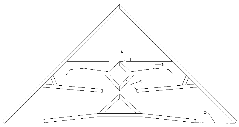
I've seen a lot of references here to "ugly" Jubilees. So I sat down this morning with a copy of the original Klipsch/Delgado JAES paper and TurboCAD, to see if I could change the external appearance while keeping the internals the same. The graphic shows what I came up with. It is now a true corner horn. The shape of the backchamber is different, but the volume is the same. The horn follows the taper described in the JAES paper almost exactly, in fact the "A", "B", "C", and "D" callouts correspond to the similarly labeled points in the paper.
Note that I haven't built this, only fiddled with it in CAD. But maybe it will give some of the DIYers some inspiration.
-
I've had an APC UPS for several years; no problems whatsoever. I like it because it provides a real sinewave output. I'm not certain whether, by "power conditioner", you mean the same thing as "uninterruptible power supply".
A few years ago I was in the local "Batteries R Us" store and saw a big pile of APC power supplies in the corner, $10/each (without batteries). I asked the clerk to explain, and he said that many people bring in their UPS when the batteries die, and when they find out the cost of replacement batteries they say, "No, thanks, I'll buy a new one," and leave the UPS behind. So you might be able to pick up a used one for a song. Then go someplace like "http://www.batterystation.com/ups.htm" for replacement batteries, and you're in business.
-
Ah; thank you. I tried Google with every combination of keywords that I could think of, but all I got was "Between the Lines" by Janis Ian.Google is amazing :-) The band was called Lake.
Greg
-
Okay; here's a band that I've been trying to remember the name of for quite a while. Late '70s or early '80s German rock band, put out one album with a picture of a sailing ship falling off the edge of the earth. Sang a song called, I believe, "Between the Lines":
"... so if you should read my book,
sure won't take much time,
make your way from page to page.
It's all between the lines."
Anybody?
Thanks,
Greg
-
Anybody know if they ever found the missing master tapes for Black Cow and Aja?
-
For anyone else who might be interested, I checked again and mine are 8 Ohm. If you really have to have 16 Ohm, I suspect that it's only a diaphragm replacement away. Check with Bill Hanuschak at Great Plains Audio to be sure: "http://www.greatplainsaudio.com/PartsList.html".
Greg
-
I am looking for a pair myself ...
See message #914769.
-
Thanks for the website. I have seen this material before, but have not used it. Looks like nice stuff, eh?
Definitely looks interesting. Note that Outwater recommends laminating two sheets with the cuts on the inside. That would be a whole lot more stable than a single sheet.
Greg
-
This makes it easier to see what Edgar is suggesting.
Thanks. How do you insert an URL so that it acts like an URL and not like text?
Greg
-
Has anybody ever tried this?: http://www.outwatercatalogs.com/2006_Master/lg_display.cfm?page_number=322... next time I will probably laminate two sheets of 1/8" Russian Birch or 1/8" MDF. Those materials just finish better if you are going with paint.
-
If you purchase any Altec multicell horn, make certain that you also get the 30210 throats with them.I suggest the 805, 1005, 311-90, or 511E with the 290 driver.
The 290 is very reasonable on the used market, as is the 805. 805 is best for short wall use, the 1005 for long wall use.
Having said that, I have a pair of Altec 1003b horns (with throats) in fair shape. They were pulled from active duty after at least a couple of decades, and are weary but serviceable. I also have a pair of Altec 290 drivers in unknown (meaning "pretty rough") condition. Any or all are free to a good home, but you have to pick them up in Colchester, Vermont (just north of Burlington). I'll help you load them into the back of your pickup truck, but that's the limit of what I'll do to transport them.
Send a private message if interested.
Greg
-
With those T/S parameters, using Keele's equations, I come up with the following for the TAD 1601a:
Vb (reactance annulment chamber volume) = 3.18 cubic feet
St (throat area) = 74.2 square inches
fHM (upper mass rolloff frequency) = 181 Hz
By comparison, I have some Eminence numbers for the K33 that show:
Fs = 34.46 Hz
Vas = 10.65 cubic feet
Qts = 0.39
Vb = 5.83 cubic feet
St = 114.1 square inches
fHM = 181 Hz
This shows the 1601 to actually be a better match to the KHorn than the K33. (If anyone has more up-to-date K33 T/S numbers, please post them and I'll run them through the equations.)
-- Greg -
THEIR SHOULD BE AN APPLACTION PROCESS TO BUY A BIKINI !
... and a license should be required to wear spandex!
-
Seems I read back when I was making my cables that I have an impedence match (more voo doo words, for this dummy)
Anyways, I recall being told with said impedence mismatch, I'd lose my high end.
Mostly it's a noise issue. Balanced cables with unbalanced impedances do not reject common mode noise as well as if the impedances are balanced. So if you have really long cables in a noisy environment (lots of dimmer switches, commutator motors, fluorescent lamps, etc.), you'll pick up noise. But it will still be better than using a plain unbalanced RCA cable.So, if you have a XLR to RCA patch cord, what's the story on a resistor and if you add it, WHERE and HOW do you add it?
See post 762412: http://forums.klipsch.com/forums/permalink/762412/762412/ShowThread.aspx#762412
It's a lot more important when going from unbalanced outputs to balanced inputs than when going from balanced outputs to unbalanced inputs.
Greg
-
Lots of good info in the old Bruce Edgar interview, in Positive Feedback.
http://www.positive-feedback.com/Issue4/edgarinterview.htm
Greg
-
It's just a term that I use to describe it. If you have low-order (shallow slope) crossovers, and the relative phases of the LF and HF drivers vary with frequency, then the angle at which the two sources add in-phase also varies with frequency. If you think of that as a lobe of higher amplitude response, then it moves around as the frequency is changed, like a searchlight."Searchlight" lobing is a term I have never hear before. Could you expalin that? Does it simply mean the lobes move around? That would make sense.
Greg
-
Um, I'm not an acoustics guy. Signal Processing is my bag.What I need is a serious coustic guy to work with to complete the "marrage" of the two sciences. Greg is the kind of guy I am looking for
Greg
-
Essentially, yes. If the delay is constant you get a comb filter. If the delay varies with frequency, you get "searchlight" lobing.I gotcha! I think you are describing ordinary "comb" effect, only vertically.
Yes, that is one way to deal with it. The other is to use broadband transducers and crossover topologies that are in-phase at all frequencies, like Linkwitz-Riley or Bessel-Derived Matched-Delay Subtractive.The thinking here is to make that frequency "window" extremely narrow and just live with it.
You can approximate it with a string of allpass filters.There is just no way to generate actual time delay with a passive network.
Greg
-
An example is best. Let's say that the low frequency and high frequency driver responses are 90 degrees apart, and that the drivers are physically separated by some distance -- the HF driver is physically above the LF driver. If the listener is on-axis, the two responses may sum to 1.0. But at some vertical angle above or below the axis (usually below), the phase difference between the drivers is exactly cancelled by the distance between the drivers, so they now add in-phase. At some angle in the opposite direction they add out-of-phase, again because the physicsl distance corresponds exactly to the phase difference. In a living room, the listener is almost always within a few degrees of the vertical axis, so this effect is only noticed in reflections off the floor or ceiling. In a concert hall, though, that axis of "in-phase", and its corresponding axis of "out-of-phase", shine like searchlights over the audience, moving around because phase varies with frequency.Could you elaborate about how the main lobe goes to the floor or ceiling.
Only if both amplitudes are equal, and both are 1/2 the passband amplitude.In the 400 Hz extreme-slope filter I build I have managed to get the loss at the crossover so that it is slightly over 6 dB. I think this gives me the Linkwitx-Riley sumation, at lest in amplitude.
Oh, I think I understand what you're trying to do. If your amplitudes are correct, but your relative phases are not, then yes, you could conceivably use delay to move the relative phases to 0 or 180 degrees at the crossover frequency. This would eliminate a peak or notch in the overall response at the crossover frequency. But it would do little to smooth the overall phase (or delay, if you prefer) response of the system across all frequencies.The phasing would be a function of the delay difference between adjacent drivers. Once that delay difference is know, the insertion phase of the filters cold be adjusted by adding elements to add skirt sharpness at the same time. That is the idea anyhow.
Greg
Jubilee Alternate Folding
in Technical/Restorations
Posted
Here's the HORNRESP response for that design with two EVM-12L inside (which I used because I just happen to have four of sitting unused in boxes). Of course, HORNRESP cannot model the effects of the folds.
And here's the HORNRESP.DAT file info: 0.5 x Pi 2.83 0.00 14.99 580.00 816.00 23.53 0.00 816.00 1727.40 59.75 0.00 1727.40 2817.66 29.45 0.00 2817.66 5527.15 44.81 0.00 500.002.12E-04 32.00 5.20 17.50 3.30 0.50 2P 80.00 40.00 0.00 20.00 4.00 376.00Two EVM12L; Alternate Jutilee 3 ConConConCon