


babadono
-
Posts
10190 -
Joined
-
Last visited
-
Days Won
6
Content Type
Forums
Events
Gallery
Posts posted by babadono
-
-
You have a digital active crossover now. I don't see why there is any limitation on boosting as opposed to only using cutting in the filters. Of course you can't go crazy and overload the unit.
I don't know if you saw my post in my Jube thread but I figured out what the front panel meters are indicating. There are showing level in dB below 0dBFS. And 0dBFS to Xilica is +20dBu. So as long as none of the red LEDs on the front panel meters are illuminating you are not overloading the Xilica. The meters in the XConsole App. are showing levels calibrated in dBu and are therefore much more useful in MHO.
-
45 minutes ago, rplace said:
Zero idea on PEQ, GEQ, ETC. Also I did all my filters and attenuation on the output side, is that reasonable?
Now you're getting into where I need to go also. This is more @Chris A 's bailiwick. I would not want to even pretend I know anything about this yet except following someone else's instructions.
-
 1
1
-
-
1 hour ago, rplace said:
So just like we were discussing previously with the 2 wire + Shield? To be clear both the Unbalanced to Balanced and then Balanced to unbalanced - the same cable creation?
Yes.
-
1
-
-
") Where are those red herrings?
Where are those red herrings?-
 1
1
-
-
30 minutes ago, rplace said:
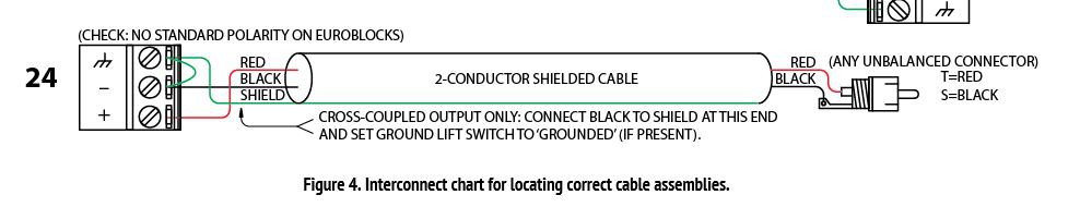
From this link https://www.rane.com/note110.html I feel this is the best bet so far for my Balanced Xilica out to Unbalanced RCA amps. Agree?
Remove jumper from minus to chassis at euroblock. Connect shield to black wire at RCA end. This will make chassis currents flow in separate conductor(shield in this case). and not in the signal ground.
-
30 minutes ago, rplace said:
From what I gather you need to know something about the balanced output device. One of the reasons I bought the Xilica was because I figured somebody here must have used it with unbalanced gear. Here is a quote from the last site I linked to
But it does not elaborate on how to know or what to do. Do you connect your Xilica to an unbalanced amp? If so is it the same connection you originally outlined with 2 wires + shield? If not what?
Thanks for all the help so far!
Yes I posted in another of your threads about this, that I have knowledge about the internal workings/topology of Xilica's output circuits. I know that Xilica's output circuit is only a balanced impedance, there is no active signal on the minus output only signal ground through an impedance that matches it to the plus output impedance. Therefore we can connect it directly to the ground of the unbalanced equipment at the RCA connector.
Thus far I have only used my Xilica with balanced inputs. But have No Fear, it will work.
-
20 minutes ago, rplace said:
Starting to see the light @babadono Yesterday I did not have the vocabulary you did and was confused about "Shield". To me they are all wires. This does a pretty good job of explaining that when you are going form unbalanced output to balanced input both ways in the picture posted will work but the one with the shield and 2 wires is better.
https://www.presonus.com/learn/technical-articles/Balanced-Unbalanced
I'm going to order some RCA ends that I can solder up and just cut both ends off some of my XLR cables I ordered to have the 2-wire + shield on my input side for the long term. Still might give it a go with my simple dual ended RCA cables with one clipped off and a jumper at the Xilica side.
As for the Balanced to Unbalanced as I move from the Xilica to amps I'm still trying to figure that one out.
A lot of Presonus's diagrams are direct copies from Mr Whitlock(see AES seminar linked above). What confusion are you still having about connecting the Xilica outs to the amps RCA inputs?
-
-
2 hours ago, CECAA850 said:
If you look closely at the diagrams you provided, both methods are doing exactly the same thing. You're running wire 1 and wire 3 parallel. The only difference is where they're joined together.
Exactly the same thing? Well not exactly. They are NOT the same. An ohm meter will tell you they are the same, but they are not. You must think in terms of where the currents will flow.
-
2 hours ago, rplace said:
After a bit of digging and a lot of reading it seems to me there are two way to accomplish this. However, I'd like some confirmation. If I'm right and you have a cable with 3 wires then you connect it as @babadono suggests with the 3 wires at the XLR end connected exactly as you would expect and at the RCA end you put the negative and ground both to the "Shield" or non-positive part of the RCA tip. If you have a 2 wire cable like cutting the end of a standard RCA you put a short wire or jumper between the ground and negative at the XLR end. I've not come upon anything that suggests one is better or correct. Should note that this seems to be for when you are going from unbalanced equipment to balanced equipment like in my case of a consumer preamp to the Xilica. I'm seeing different approaches for going the other direction as in a balanced device to a non balanced device such as would be the case when going from the Xilica to a consumer amp.
Thoughts?
You must think in terms of where the chassis currents and signal currents will flow. These two arrangements are NOT the same. The diagram does not explicitly show that the black wire is a shield. In the 3 conductor cable the chassis current on pin 1 of the XLR will flow on a separate conductor(the shield) all the way down the cable until it gets to the RCA connector where it will tie to the chassis of the unbalanced equipment. The signal ground current on pin 3 of the XLR will flow through the blue wire of the twisted pair until it gets to the RCA connector where it connects to the same point as the shield, because in unbalanced equipment the signal ground and chassis ground are the same point. In the 2 conductor cable with pins 1 and 3 of the XLR jumpered together the chassis and signal ground currents flow in the same conductor(most likely a shield). This can cause Common Impedance Coupling(CIC). The 2 conductor arrangement is used all the time but is not optimal. Someone may use it satisfactorily for years and then they add a component to their system or just move their system and start having problems because the chassis ground current couples a signal onto the signal ground and the unbalanced equipment has no mechanism to discriminate between wanted and unwanted signals.
-
1
-
-
2 hours ago, dtel's wife said:
Trip to the ER with the worst pain ever....kidney stone.
Ow. Hurts just to think about it. I hope you are feeling better.
-
 4
4
-
1
-
-
2 hours ago, CECAA850 said:
I'm sure my wife would like this part:
"The wife, on her part, ought not to be less desirous than she was in the days of courtship".
I'll be in the garage.............................
Be nice. We know your wife. And we like her.
-
3
-
1
-
-
20 minutes ago, rplace said:
Now I'm confused again. That is what I already have. A cable with a RCA male on one end and a XLR on the other.
If the RCA end is wired properly you're good to go. But I thought you said the RCA to XLR is only 2 conductor. Is it 2 conductor PLUS shield?
-
1 hour ago, rplace said:
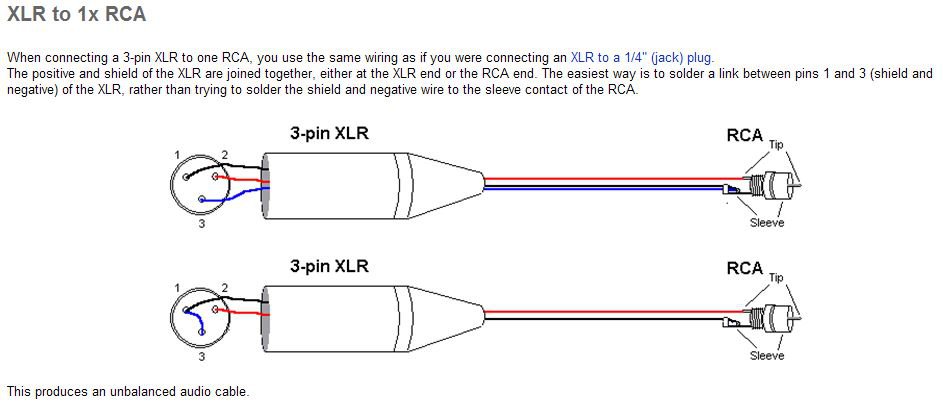
So I've reread your post a few times and googled twisted pair with shield. Are you saying to get a wire like below and make the phoenix end like normal +/-/G and at the RCA end solder up the + to + and the - and Ground to the "other" part of the RCA? I must admit I've never made my own RCA or soldered one. Guessing there are two places for wires to attach on an RCA and it will be obvious which is which with some searching.
So normal Phoenix end with home made RCA connection?
Yes. Or order some of these in the length needed. Lop off (or un solder)the XLR end. Use the resulting bare wires into the phoenix connectors:
You will see from their wiring diagram the proper way to wire RCA connector to a balanced cable
-
21 minutes ago, richieb said:
--- Oh my. French coming from an Italian. Not sure whether you should retreat or charge ahead?
Advance to the rear.
-
https://www.monoprice.com/product?p_id=5279
Get one of these in the wire gauge and length of your choice. The ground prong won't attach to anything anyway. Should still work.
-
The output of the Xilica is balanced impedance but there is NO SIGNAL on the minus output. It is just ground through an impedance that is equal to the plus output. Does your cable have 2 conductors or 3? The best way to wire this type of output to an unbalanced input (RCA) is using a 3 conductor cable (a twisted pair with a shield). The minus conductor of the twisted pair would then be connected at to the shield AT THE RCA connector along with the shield. This allows the inter chassis current to flow through the shield and not the signal conductor.
-
7 minutes ago, rplace said:
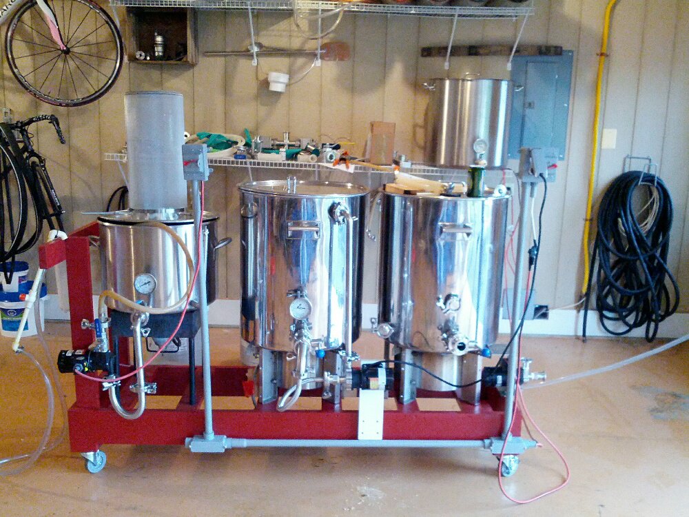
Just like our music systems keep evolving so does my beer making rig.
I be thinkin' yours is much better than Duff's.
-
2
-
-
17 minutes ago, CECAA850 said:
I'll be insulating the door panel also. There's one window in the garage and it will get a double pane argon filled replacement.
AC and argon insulated windows in a garage? This man spends some serious time in his garage
Come to think of it I am contemplating moving the pellet stove I just removed from the corner in the basement where one of my Jubes resides to my garage.
-
Are you sure you and some of your beer can't make it to Hope next year?(Selfish unabashed request)
-
1
-
1
-
-
34 minutes ago, rplace said:
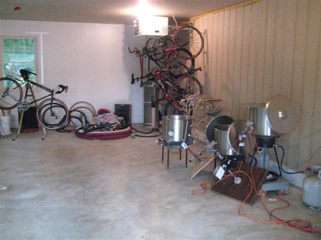
Cheated on mine. Insulated garage doors, insulated ceiling and walls. The front where the doors are has a people door in addition to the two large garage doors so probably less than 10' feet total of 33' that are not doors. I've just got brick on the outside and 2X4s inside, no insulation/OSB.....oh, crap now that I think about it OSB is that funky looking chip board right? I'm sorry not OSB in the inside walls I think it is call T1-11. Sort of a paneling look with a tongue and groove overlap. Much cleaner/neater looking than OSB. Comes prefinished, no need to paint and very durable. I'll see if I can dig up a picture of my actual garage. I'm very happy with the T1-11, not OSB inside.
Give this some consideration as the finished wall inside covering up the insulation.
EDIT: Here is a picture from very early after construction. The back wall looks white but that is the pegboard. Right wall is the T1-11. Still looks like the picture many years later. Could not be happier with the outcome. Heater and Heresy II visible in the back.
Mmmmmm....Beer
-
2
-
-
1 hour ago, muchilus said:1 hour ago, tigerwoodKhorns said:
Are you using mini split HVAC systems for your entire house?
If so, how well do they work?
I do use berinher 3 way active crossover. Xlr.
I think something got lost in translation
-
Just killed a good sized scorpion in the master bath bathtub.
When I get to heaven I will ask the Lord how this happens.
-
2
-
-
3 hours ago, mangofirst said:
Mug o' the day.
And nails to match
I like.
-
5
-


XLR to Unbalanced RCA to Phoenix
in Technical/Restorations
Posted
Files will have an extension .XDAT. Store them on your computer in a new directory of your choice. I call mine "Xilica Files" Imagine that") . Do you have the XConsole App. up and running? And are you connected to the crossover? I am assuming you are. If so you will be able to open the .XDAT file and download to the crossover. Then store it in the crossover so you don't have hook up your computer all the time.
. Do you have the XConsole App. up and running? And are you connected to the crossover? I am assuming you are. If so you will be able to open the .XDAT file and download to the crossover. Then store it in the crossover so you don't have hook up your computer all the time.