captainbeefheart
-
Posts
1422 -
Joined
-
Last visited
Content Type
Forums
Events
Gallery
Everything posted by captainbeefheart
-
I did make a mistake, I was mucking around with it and saw I used a 12AY7 instead of a 12AV7, they are similar but not the same. Will retest with the correct driver tube. Sorry about that. When building no feedback amps it's paramount to select the most linear tubes, the EL34 is in my opinion a much better tube triode strapped compared to the 6L6 types. I never liked the 6L6 types even with feedback so I just stopped using them a long while back. I like your circuit with the EL34 and have made similar no feedback amps. It's probably the most popular topology for single ended amps coming from China but you see 6N1 (similar to 6DJ8) or 6N3 (similar to 5670/2C51) as the front end stage tube. That and the other very popular driver arrangement is just placing the two triodes in parallel, those are often a 6SL7 but also have seen them use 6N1 or 6N3. The output stage is usually wired UL with triode switch. I like the style driver you used (half mu follower?) the best from all the China amp versions , they sounded better than the versions that came with the triodes in parallel. All sounded best to me in triode mode. A couple friends of mine were real heavy into these Chinese amps and I helped them modify them into all kinds of different circuits over the years. I think the two of them bought 10 of them between the two of them. That's how I got to finding out the output transformers aren't really all that bad that come with those amps, we got some really good results with them.
-
You were dead on with the triode wired 6L6. I ran the circuit with a 6L6 this time and the results were: At the same input of 1.2v peak, power out is a hair over 2 watts at over 7% THD. The EL34 triode strapped does sound pretty good and is the clear winner, well at least for me I'd use the EL34 with this circuit.
-
Just did a simulation of the entire circuit and the driver doesn't change anything drastically. With 1.2v peak input you'll get 3.125 watts output @ 5% THD
-
Yes I know you were asking for info on the triode strapped version. Just wanted to clarify about the 8 watt original pentode amp. With a perfect driver (no distortion) the EL34 triode strapped with this operating point will be about 3 watts at 5% THD Clipping occurs at 4 watts.
-
That schematic shows pentode operation, the screen is tied to B+ not to the plate. Hence the 8 watts output power. Triode mode one can expect maybe 4 watts.
-
Little Sweetie Forum amplifier project
captainbeefheart replied to henry4841's topic in Talkin' Tubes
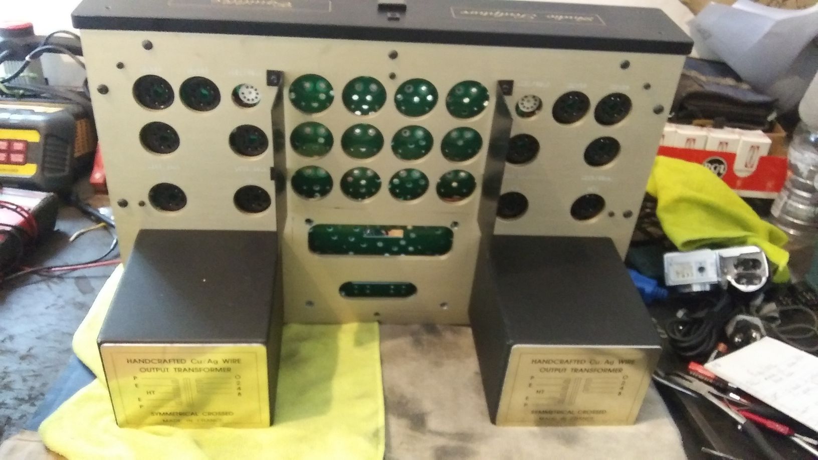
Here is that monster extended Class A amplifier. Notice the massive power transformer that failed and I had to pull from the potted enclosure, that wasn't fun at all. The owner isn't sure what he wants to do, rewind the power transformer or outfit a custom made one. Both very expensive endeavors. It's been here like a year and he still doesn't know what to do.
-
Little Sweetie Forum amplifier project
captainbeefheart replied to henry4841's topic in Talkin' Tubes
Yes since the beam forming plates are still at a DC reference they are still considered a "fifth" electrode, it's just not a screen grid. Some datasheets even call them beam pentodes. When the patent was around they didn't use the word pentode. -
Little Sweetie Forum amplifier project
captainbeefheart replied to henry4841's topic in Talkin' Tubes
No I haven't run the older 6BG6s at all, only the 6BG6GA which as you said will run at 30 watts all day without problems whatsoever, it's a very rugged and well built tube and great for audio. I actually re-wire old Heathkit W5m's to run the 6BG6GA instead of the very expensive KT66. Performance and sound is identical between the two. Big fan of 6BG6GA! -
Little Sweetie Forum amplifier project
captainbeefheart replied to henry4841's topic in Talkin' Tubes
One way of getting more power but keeping the low power detail of a triode output stage is what's known as "extended Class A". It was first introduced in the 50's and used 807's in parallel, one triode strapped and one pentode wired. Since the triode strapped 807 requires much more bias voltage the pentode wired 807 is effectively at cutoff during idle and out of circuit. Feedback within triodes: The reason for poor power is when the plate swings low with a triode it decreases current through the tube. When the triode strapped 807 swings large signals the pentode wired one comes into circuit pulling the current up through the load effectively increasing the output power. So you have the same change in voltage but higher change of current. The amp was introduced as a push pull amp but we can do a single ended version. I have made a push pull version before and they do sound amazing but I have never made a SE version of that circuit. We don't have to use 807's either, many tubes work well with this arrangement and you can even use different types of tubes. I have one here with triode wired EL34's and pentode wired KT88's I am working on. The thing is a BEAST!! If anyone wants the PDF of the circuit let me know. -
Little Sweetie Forum amplifier project
captainbeefheart replied to henry4841's topic in Talkin' Tubes
I agree, just about anything drives my La Scala's but my Heresy's, not the case. 5 watts is close to being acceptable if you don't want to rock out but to work well with all heritage series speakers I'd shoot for around 10 watts output so everyone can get in on the fun and not just the horn guys. I did a sim of the EL84 triode strapped and 6SJ7, pretty much dropped right into the sweetie with the exception of changing the bias resistor to 270 ohms and increasing the plate supply to get 250v across the EL84. 2 watts output at 4.5% THD But it only takes 170mV peak to drive to full output so we have plenty of gain to add feedback which will only make the amp better anyway. -
Little Sweetie Forum amplifier project
captainbeefheart replied to henry4841's topic in Talkin' Tubes
Nope, I was wrong and you are correct. I just looked at some curves for triode operation of the 6BQ5 and it shouldn't change bias/drive voltage all that much. Some tubes have very low drive voltage in pentode mode and then require much more for triode mode but that's not the case here. We also have 6AQ5 options as well. -
Little Sweetie Forum amplifier project
captainbeefheart replied to henry4841's topic in Talkin' Tubes
Yes in Pentode mode they tend to bias up around -12v, but triode mode will be closer to -25v me thinks. I'll have to look at some triode curves for it. -
Little Sweetie Forum amplifier project
captainbeefheart replied to henry4841's topic in Talkin' Tubes
Actually the triode strapped 4P1L could ideally have a low enough bias voltage to directly couple them like the Mullard 3-3 circuit. That actually might make one amazing SET amplifier right there. Instead of the Pentode output stage and 20db of feedback we can run the 4P1L as a triode and still have enough gain for some negative feedback. Since the 4P1L is so linear as a triode we won't need much feedback but it will help with damping, bandwidth, distortion and noise. -
Little Sweetie Forum amplifier project
captainbeefheart replied to henry4841's topic in Talkin' Tubes
I was thinking more about the Mullard 3-3 amp and the sweetie, the output tube would have to be pentode strapped to reduce bias voltage down low enough to DC couple the stages. 30v bias is just too much to put at the screen of the 6SJ7 for starved operation. Ideally, we would want a bias voltage of 10-15v. With the increased bias resistor set the cathode for 30v, and the plate of the 6SJ7 can be put at 20-15v for proper bias of 10-15v. With too much voltage on the 6SJ7 screen it pulls too much current for starved operation and it won't bias up properly for grid leak bias. With the 6Y6 triode strapped and a bias of 30v, it would need to be about doubled to 60v with increased bias resistor. The plate would then be run at 30v giving us the -30v bias from grid to cathode. I just think 60v would be too much on the screen for the 6SJ7 and would increase current too much for starved operation. I'm not 100% positive, it's just preliminary thinking. I would need to breadboard and play around with it to see how well it works. But ideally it would be better to have an output tube with a much lower bias voltage, something in the area of 10-15v. -
Little Sweetie Forum amplifier project
captainbeefheart replied to henry4841's topic in Talkin' Tubes
If one is happy with a few watts there is no better tube in triode mode than the Russian 4P1L. It is more linear than actual real triodes like the 45 or 2A3. In open loop (with no feedback) it will outperform EL84, 6V6, 6Y6 etc.. when strapped as triodes in both performance (low distortion) and sound quality. I have built so many amplifiers I cannot even keep track of them. I have designed many amplifiers and heard many many more. From this experience I am here to say the 4P1L is the best triode strapped tube out there, it just sounds heavenly. It's easy to drive so driver performance plays a role in the performance also. Magical tube if there ever was one. Parallel a pair if one wants more than 3 watts. I haven't experimented with push pull designs with the 4P1L because it sounds so lovely in single ended mode but it's on the eventual to do list. I sent Nick some to try, hoping he likes them as much as I do. -
Little Sweetie Forum amplifier project
captainbeefheart replied to henry4841's topic in Talkin' Tubes
The basics from the Mullard 3 watt amp is what I was trying to get people to mod the Sweetie amp to; Run the first stage in starvation mode. DC couple the two stages by increasing the 6Y6 bias resistor. Use the 6Y6 cathode voltage to power the screen of the 6SJ7 All can be easily done if one wanted to try different schemes of the Sweetie's setup. I can work out the exact values and voltages for the changeover. As for output tubes, why not something more powerful like a 6BG6GA which is cheap and plentiful but also rated for 20 watts. Mind you that rating is for horizontal deflection duty and for audio applications is more a 30 watt tube like the 6L6GC. I use them a lot and they are fantastic tubes, plus the plate top cap looks neato. -
Little Sweetie Forum amplifier project
captainbeefheart replied to henry4841's topic in Talkin' Tubes
I use KiCad with Ubuntu for lots of my audio projects and like it. Easy to use and pretty flexible, lots of various footprints for parts in the library. Lately I haven't been making PCB's for audio since tubes lend themselves so nicely to p2p wiring. l -
Little Sweetie Forum amplifier project
captainbeefheart replied to henry4841's topic in Talkin' Tubes
@henry4841 I think you would really enjoy making turret boards for your power supplies, it's actually quite easy. The kit to install them is cheap, I just purchase the epoxy boards in bulk and cut to my own size. The kit comes with the exact size drill bit and the install tool and swage tool. Basically you just pound them in the board as they are compression fit then swage the underside. They are very heavy duty and hold components nicely, they also dress the build up substantially vs the perf board. Another thing to play with is PCB boards. For these simple designs you don't even need a computer to make the files. Just purchase double sided clad board and draw your circuit traces with a heavy duty permanent marker. Once you have all your traces covered with the marker just soak the board in Ferric Chloride and after it eats the remaining copper away clean the marker off and drill your holes. I once did it this way for easy circuits but now I just use software, for development I'll print the circuit out over glossy paper with Laser jet printer. Typically just bring the files to Staples since I don't have a nice printer. Then heat transfer the traces from glossy paper to clad board. Soak in the mixture and remove and voila a nice prototype board to see if it works before sending the gerber files out for production. Just other fun ways to make boards for builds. -
Little Sweetie Forum amplifier project
captainbeefheart replied to henry4841's topic in Talkin' Tubes
For people interested in breadboarding, having a DC power supply is the only way to easily work out circuits for me. I don't have a tube DC supply, I went SS that way it can be efficient and adjustable and fully regulated. I have two, one is a Miada regulator issued in pdf back in the 90's that uses an LM317 floating. Then I have another heavy duty one with large heatsinks and pass transistors. If I want to test a specific tube at a specific B+ I just dial it up and it's ready to go. I work all my circuits out this way before even building the power supply. -
Little Sweetie Forum amplifier project
captainbeefheart replied to henry4841's topic in Talkin' Tubes
Nope, no special spreadsheets or calculators, just the datasheets, paper and pencil tells all one needs to know about where the tube should be operating given the specific circuit it's attached to. Honestly after engineering amps for so long you learn to memorize specific tubes properties, mainly just need to know mu, plate impedance and transconductance. Grounding is one of the most misunderstood concepts in amp building. Many have a "recipe" they use that works good and they stick with it. Glad you got it all straightened out and quiet. -
Furman uses center tapped secondary isolation transformers so when referenced to the center tap common mode noise on the input side is cancelled. Noise is measurably better on the secondary but what you will see for improvement will depend on how well built your specific gear is already. From what I have found to be the most notorious creators of noise are electronics that somehow got by without much filtering. I don't mean filtering from mains to itself, I am talking about filtering of itself per FCC regulations to not pollute the grid. For example I have two audio systems in the garage, when I plug my battery charger in to use it one of my systems gets so polluted with noise from the battery charger it's not even listenable. Does that mean the stereo is bad or the charger is bad? A little bit of both. Clearly the charger was not held to strict regulations or got by them somehow for not polluting the grid. Most new devices utilize switch mode power supplies that wreak havoc on the grid, the FCC has regulations for manufacturers to have filters at the device power input to block it from polluting the grid. In fact that's why switch mode power supplies have so much filtering at their input is because they have to per these regulations. The best results come from power conditioners that don't just isolate between the "power amplifier" outlets and "digital/analog source" outlets but more so have isolation between each and every source outlet. The reason being is if you plug one noisy device into the isolated outlets it can pollute them all. My own system is very low powered so I just plug my power amps directly into the wall which is fine for most well built power amplifiers. My sources, are the only receptacles that get special treatment. Each one is isolated from each other via common mode chokes and X/Y capacitors. That way there if you plug something in that pollutes the mains then it's isolated from the other sources that are also plugged in. Typically you see isolation transformers like the Furman that have center taps that isolate the noise from mains but the secondary outlets don't isolate from each other. I have seen inside much more expensive conditioners separate isolation for each outlet which is really the way to go. For the money you got a steal and Furman is a household name brand in pro audio. Great find.
-
Little Sweetie Forum amplifier project
captainbeefheart replied to henry4841's topic in Talkin' Tubes
Shingles can be quite painful. I wish your girlfriend a quick recovery and that the symptoms aren't severe. Weird fact I never had Chicken Pox as a kid or adult. I wonder how many others in here also haven't had Chicken Pox. Or if they have got Shingles later in life? I have known several people later in life to develop Shingles from their previous bout with Chicken Pox early in their life. Weird how something can lay dormant for so long waiting for your immune system to become weakened then attack again decades later. Life is weird. -
Here are the main takeaway point which hopefully may clarify and make it easy for you. Basically you want to roughly set bias at ambient temperature. Don't get hung up too much on making the initial settings of .15v perfect because transistors have a large tolerance and will drift after being warmed up. Music or not while letting warm up may not make a huge difference but I'd just do it without any music because Class A devices will be at their highest dissipation at idle. After it has warmed up take the readings again and if they are between .30v and .35v you don't need to do anything all is well. If they are above or below that region then adjust. If one is .35v and the other is .30v you can leave them or if you want optimal matching between channels then adjust them closer to each other. Go very slow moving the trimpot in small increments and wait after making an adjustment. The transistor will need time to settle before making another adjustment.
-
Yes as the transistors warm up they'll conduct more current. From the man himself: Initially we bias the amplifier low and let the bias drift up as the temperature of the transistors rises. Most of the time the bias will drift up about 50% or so from cold to hot operation. The two voltages on each channel are the bias current (measured as the DC voltage between the two pads labeled VB) which is the voltage divided by 0.75 ohms, and the DC output voltage, which is between the single pad labeled GND at the front of the board and the pads labeled VO (one for each channel). Initially the values will be at or close to 0 volts. While keeping an eye on both the VB and VO, slowly alternately turn P1 and P2 clockwise. Eventually you will see some voltage appear (don't worry if it's a minus voltage). Oh yeah, remember to turn on the switch. We are looking to have a VO of 11.5 volts and a VB of about 0.15 volts. Keep alternatively adjusting the pots clockwise until you get to these voltages. Sometimes you might have to back off one one pot to get both these numbers aligned. It's a little tricky, but it doesn't have to be very accurate at this point - we will fine tune that after the amp has had a chance to warm up. When you get close to these voltages, just sit back and watch the drift, no hurry, no drama. Ultimately you will want to be at VO of 11.5 VDC and VB of 0.30 V to 0.35 V (0.4 Amps to 0.46 Amps of current). If you have a cool room or lots of ventilation you can venture into the 0.35 V territory. If not, there is little performance penalty at 0.30 V and that's how I run them in my system. You will see some longer term temperature drift, so after you think it's stable on those voltages, keep an eye on it for an hour or so anyway. The VO is not very critical, and the range of 11.4V to 11.6 volts is plenty good enough
-
You are going to want to bias it down a nudge. With the amp at ambient temperature set the VB to .15v Let it sit for around an hour to warm up then come back and make sure it's around .30v to .35v One could avoid this by using Lateral Mosfets that have a negative temp coefficient unlike the vertical types with positive temp coefficient. The hotter they get the more current they pull.