
John Warren
-
Posts
2263 -
Joined
-
Last visited
-
Days Won
1
Content Type
Forums
Events
Gallery
Everything posted by John Warren
-
Leave it alone. Measure the Anode current of V4 and then on V5, compare. The amp should be at idle, no signal at the inputs. A close approximation of the current can be obtained by using a DVMM (FLUKE 117 for example) switched to mA DC with the common lead (BLK) clipped to the 380VDC B+ center-tap on the output transformer primary and the positive lead on PIN 7 of V4 (and then V5). The readings should be close say 2mA within each other and measured at the same B+ voltage. If they're off, say by 4mA or more then one tube is working harder than the other and push-pull symmetry lost. When the two are working in symmetry the 120Hz HV ripple in the B+ line is cancelled out (common mode rejection). Note that Anode current varies with wall voltage because B+ varies with wall voltage. There is risk of electrocution when making these measurements. The measurement raises the DVMM to the B+ potential, in your case about 380VAC. A good DVMM can perform this measurement with no issue. Do not use probes, the safe way (the only way I would do it) is using Pomona mini-grabbers or probes with extendable clips. On the meter side banna plugs that hold fast. If you short the B+ to ground you'll explode the 380V supply. Make the two connections with the amp off, set the meter to mA DC and preferable bring the amp up to 117VAC with a Variac whilst monitoring current draw and B+ voltage. The amp (or Variac) should have the proper rated fuse or one 1/2 amp lower. Then repeat for V8, V9.
-
DC balance?
-
The center-tap at the 380VAC secondary section is a floating chassis ground. The RCA phono plugs jacked into the amp from any source with a three-prong plug will tie the "floating" chassis ground of the amp to the Earth ground prong at the wall socket. If hum goes down in volume, the signal has a low impedance path to ground and sinks to the wall prong.
-
I haven't given that question any thought. Not clear yet if I want to offer the boards for builders, it's a bit complex. I also want to get the pre-amp sections build and tested but the Coronavirus shut my PC board supplier down on the west coast. Power output should be in the 30W RMS/ch. The 1650Ps are 60W transformers.
-
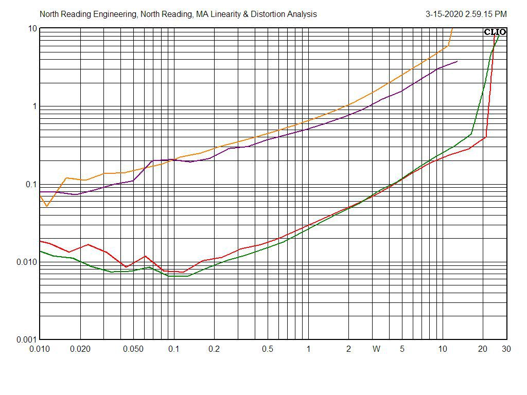
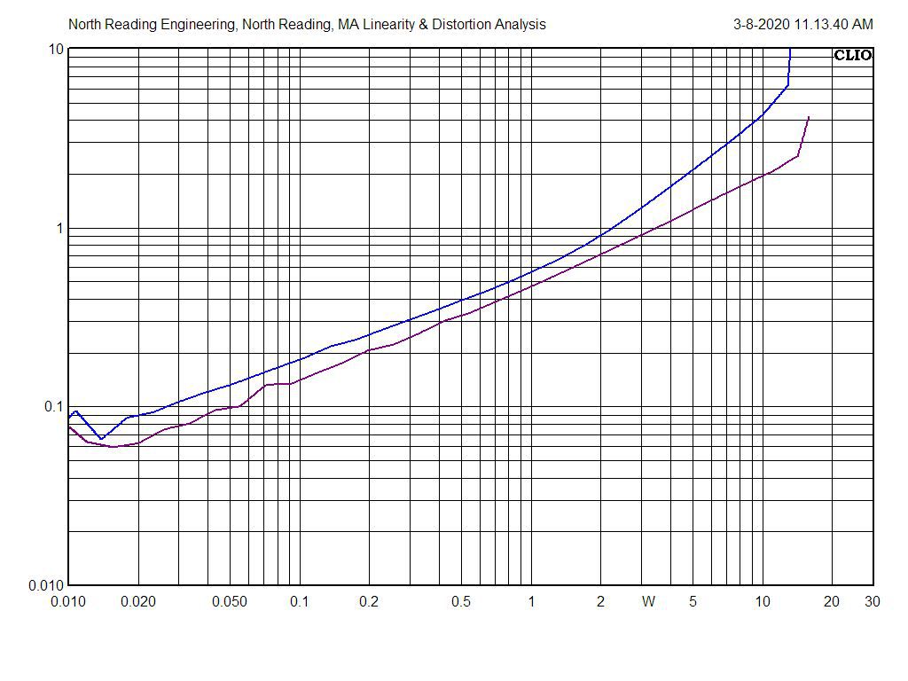
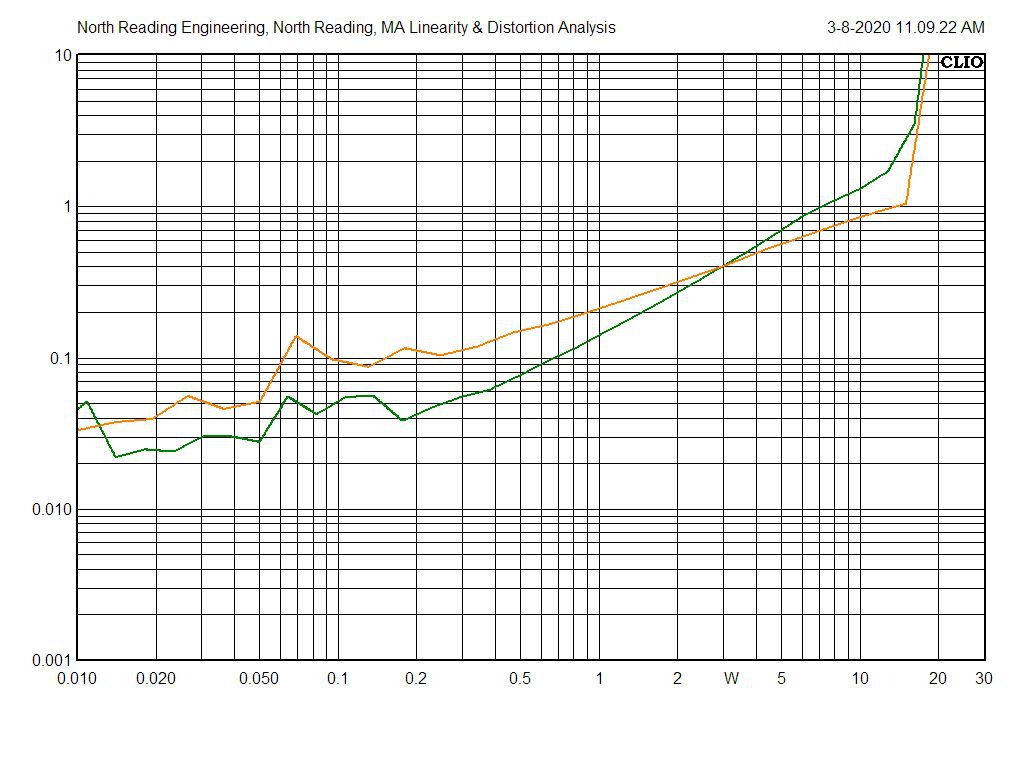
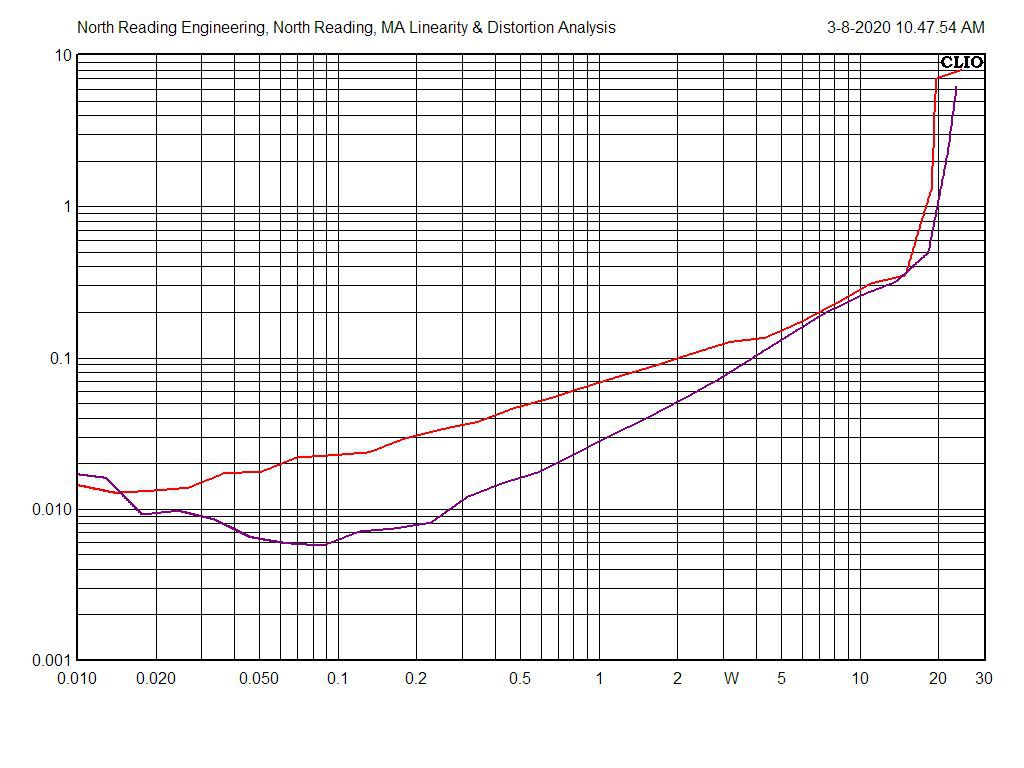
CHA and B distortion with the Hammond 1650P output transformers at 1kHz (GRN, RED) and 15kHz (YEL, PURPLE). 15kHz testing is very hard on the tubes. Load is 16Ohm resistor on each channel. For a tube amp, the responses are quite good!

-
Spent today getting the output modules stable with the Hammond 1650Ps output transformers.
-
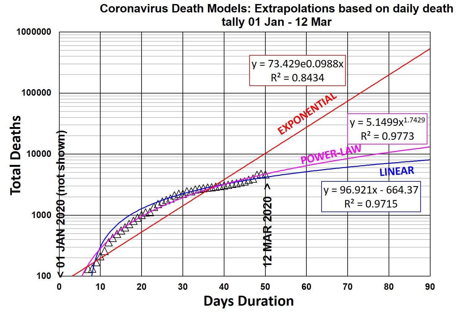
Looking for that Exponential uptick. The social distancing and the lifestyle changes people are making may keep the curve trending along Power-Law extrapolation. It's optimistic outlook.
-
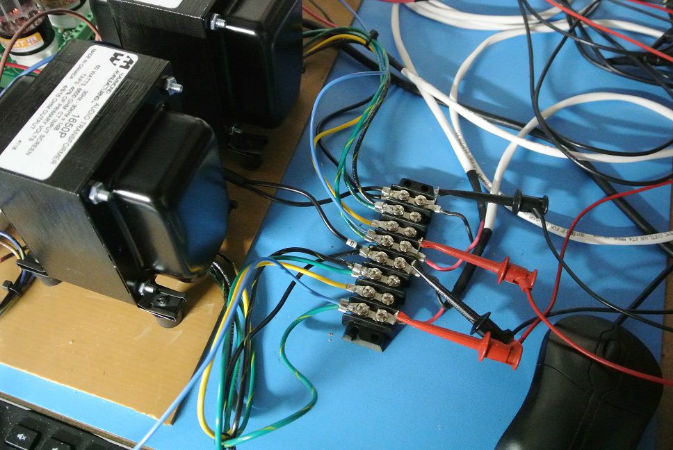
Absolutely, they're reliable and hold firmly. 250V hold-off capability between connections. Love them!
-
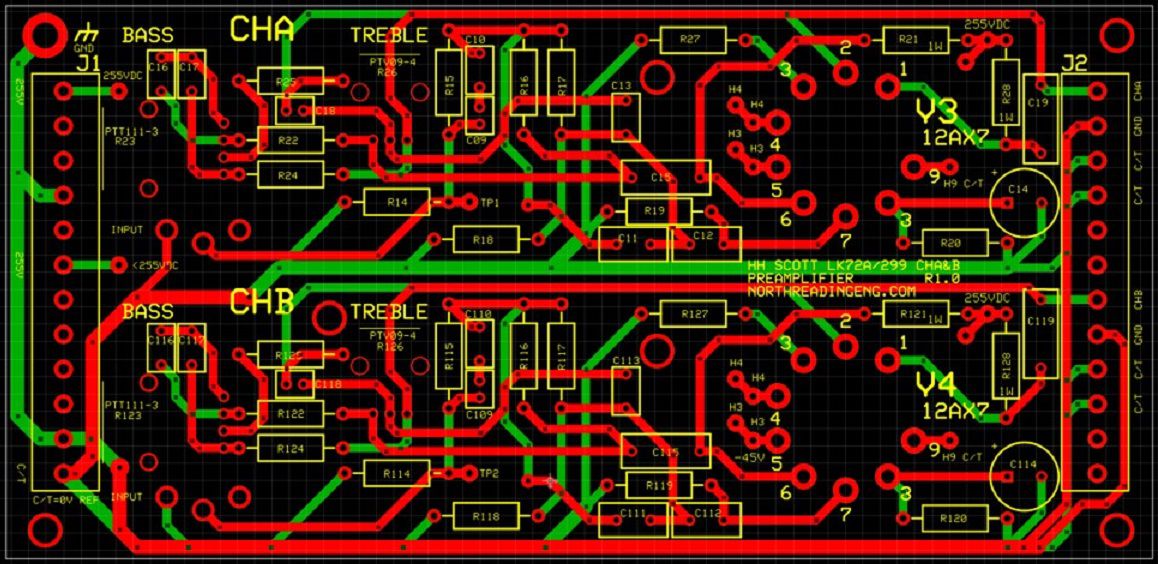
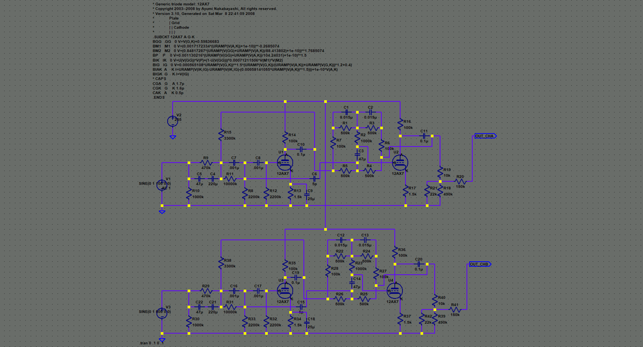
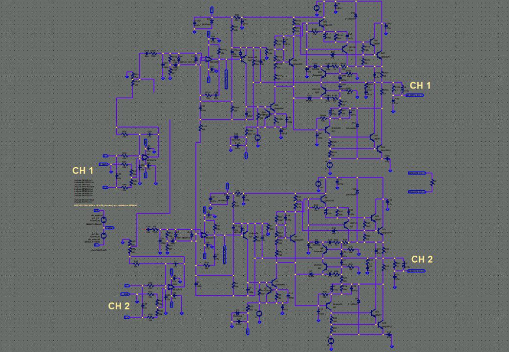
Here's the Preamp section. Manages to squeeze two channels onto the board. Has Bass/Treble adjust! Uses 12AX7. 255 VDC taps off of the HV supply board and -45VDC for cathodes sourced from on-board supply located on CHB output module.
-
If the OTs are good and the supply transformer works you could have a "project" on your hands! FWIW, I am sourcing a chassis and preamp boards for this effort. Also, Heyboer makes a killer replacement power transformer for the LK-72A and 299C.
-
The bottom plot is the FDBK sent to cathode of the 6GHB Pentode section. It's global FDBK (top plot) and sourced from the top of the OT secondary. It shows how the filter was modified to tame the beast. This is where circuit simulation comes in, makes life a lot easier.
-
Now at 15kHz the OEM transformer does a better job, that's because I'm attenuating the 1650P at the higher frequencies to calm the beast at 56kHz. Load is 16Ohm wire wound resistors. 15kHz testing is hard on tubes, they sing loudly as the high power levels are reached. That means mechanical stress and potential for damage.
-
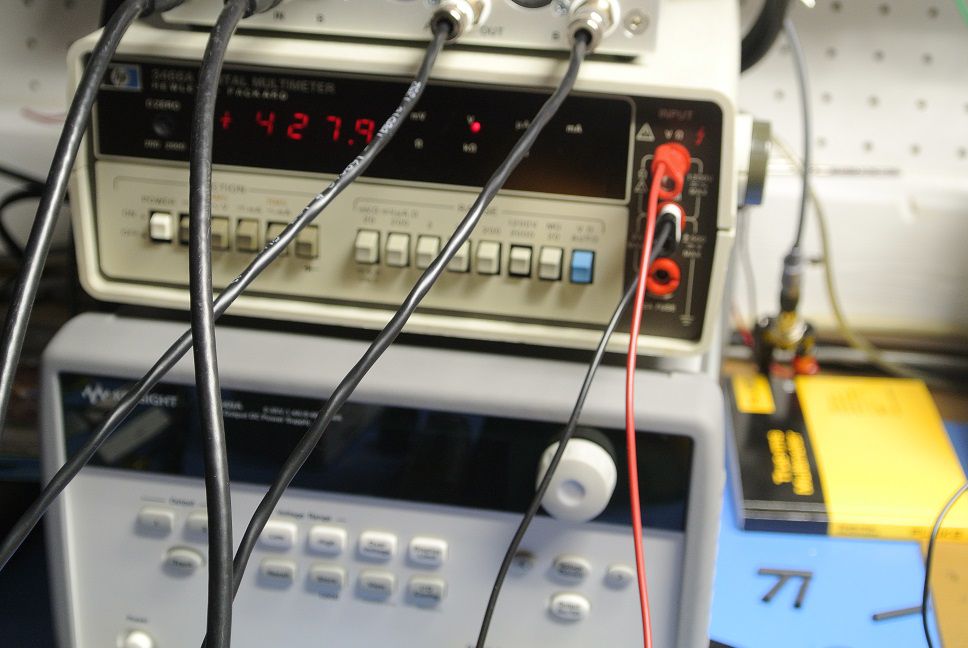
I've reproduced the circuit faithfully, same component call-out IDs, level adjust for each channel, channel balance and even a center channel out. Beefed up the HV power supply and the -45VDC supply can supply about 2A of current. In an earlier test of the HV supply, I tortured it by step loading it up until either a trace lifted/melted or I blew-out the fuse. It was able to provide close to 8AMPS at 425VDC and didn't burn a trace but it did pop the fuse and smoked the rectifier tube. That's over 3kW of power!
-
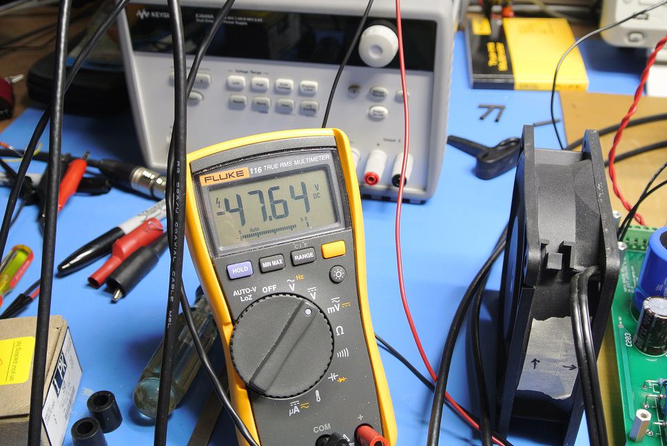
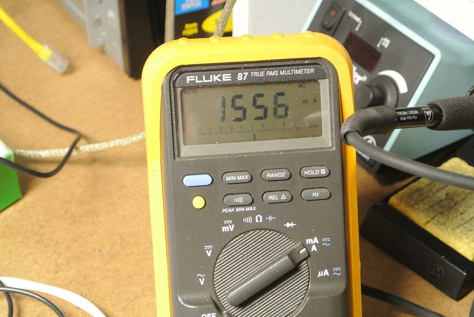
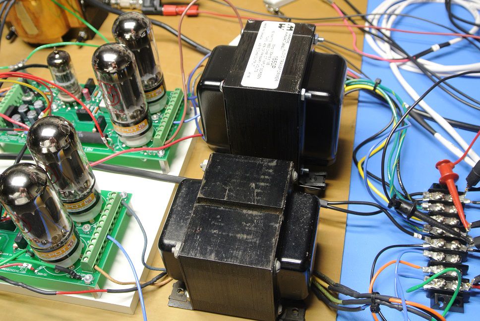
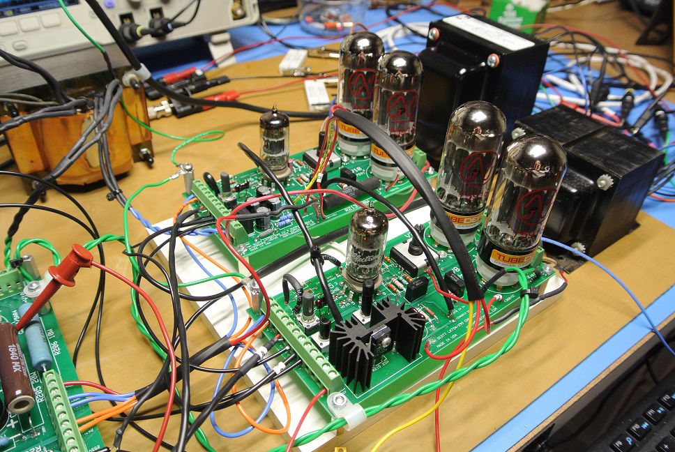
B+ comes in at 428VDC The two modules draw about 1560mA AC at 117VAC The -45VDC (on-board) for 12AX7 (x4) preamp modules and DC bal pots comes in at a little under -48VDC. For this test, the 12AX7 filaments are simulated using a 340Ohm power resistor that gets HOT AS HELL. I used a muffin fan to cool everything because I was starting to get warm hanging over this setup with probes.
-
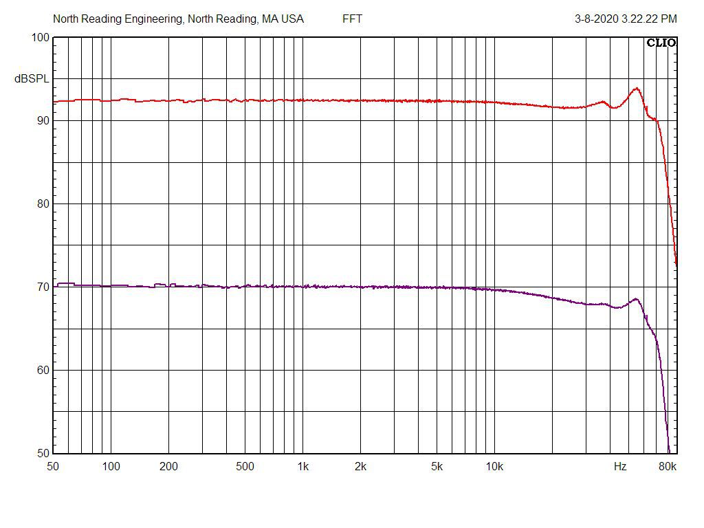
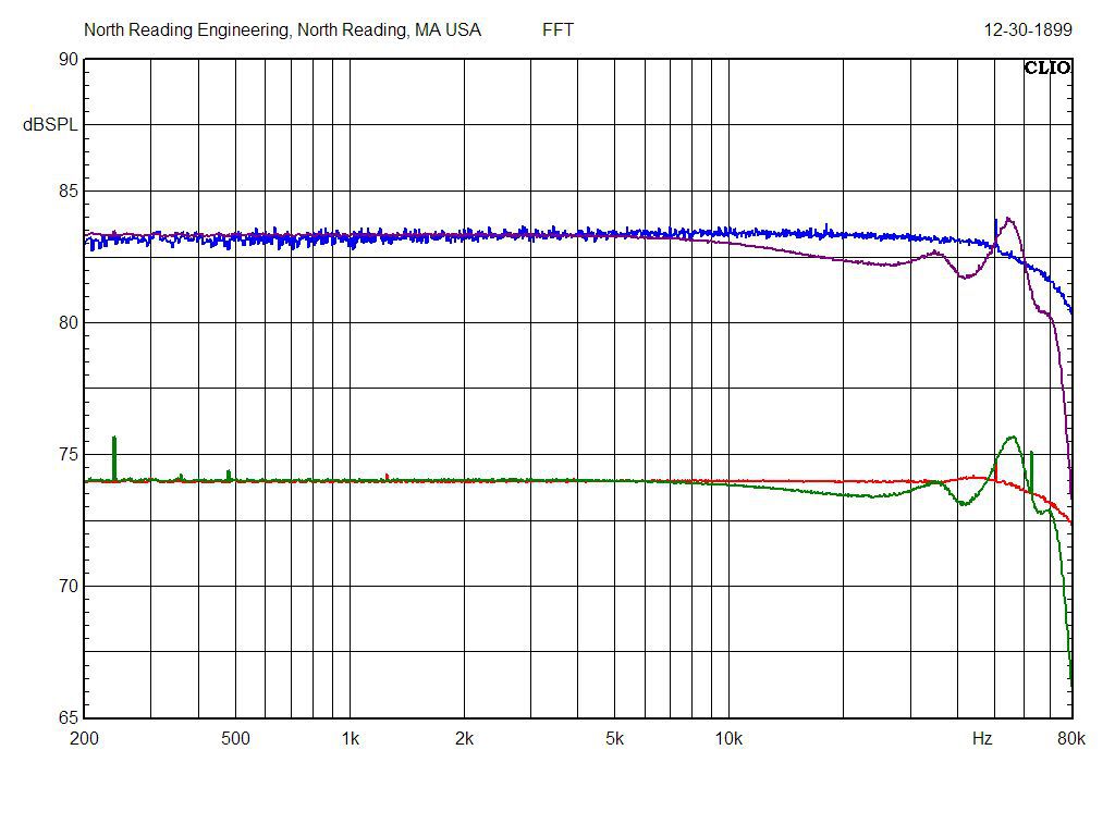
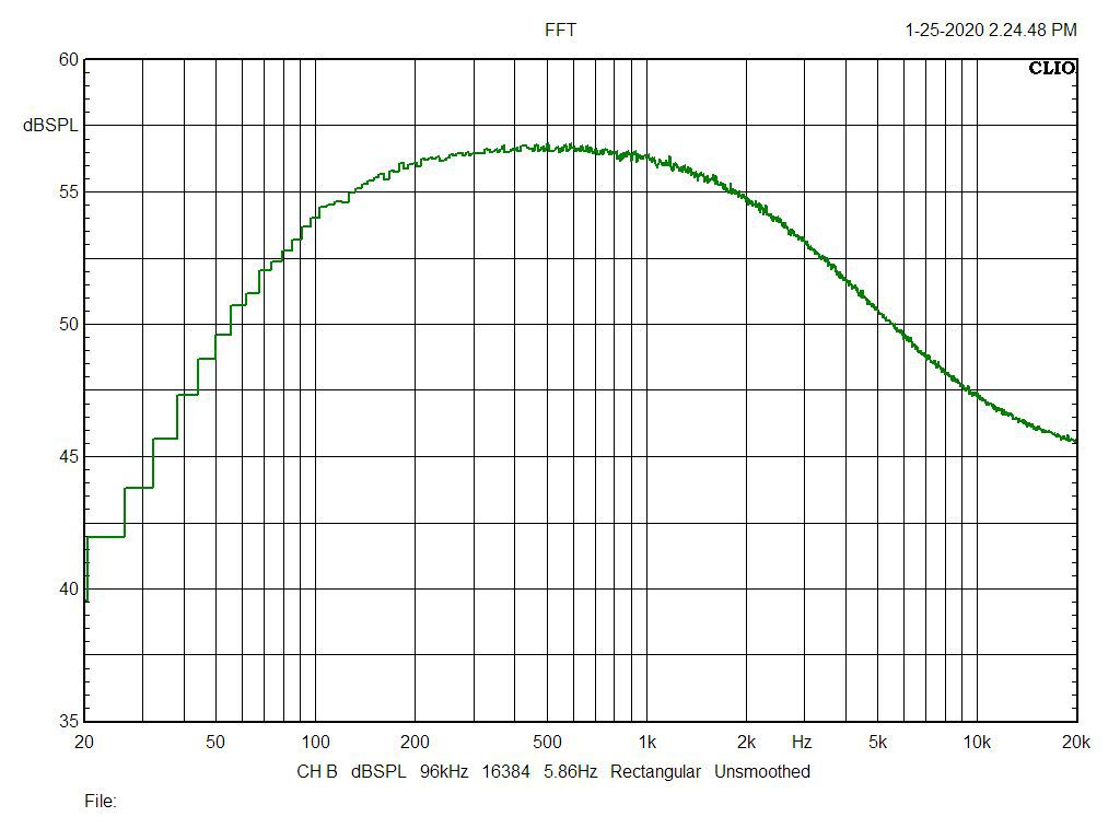
Hi Edgar, Yes, they're my "creations" but not so sure I'd call them products. As you can see, they're really not for the faint of heart! jw FFT of the two OTs, two different output levels. The OEM OTs are a wee-bit less "wiggly" but I can improve the response of the 1650P with a little tweaking!
-
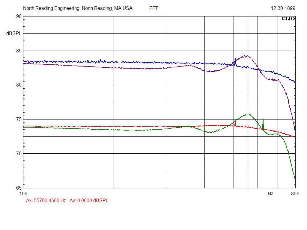
Here was the problem. There was a NASTY oscillation in the neighborhood of 56kHz that needed taming. This is the FFT with the medicine applied, about 4dB bump and stable at all output levels. The oscillation was well over 12dB using the OEM FDBK loop. The blue and red plots are the OEM OT. Two output levels are shown.
-
1650P and the Scott TR-11-2. The 1650P is 6600Ohm P-P with 16/8/4 secondaries.
-
Some %THD data at 1k (bottom) and 10kHz. The 1650P seems to be a wee bit better at both frequencies. Needed to tweak the FDBK loop off the OT secondary to avoid a nasty oscillation using the 1650P. Load is 16Ohm wire wound resistors. All's good with the world.
-
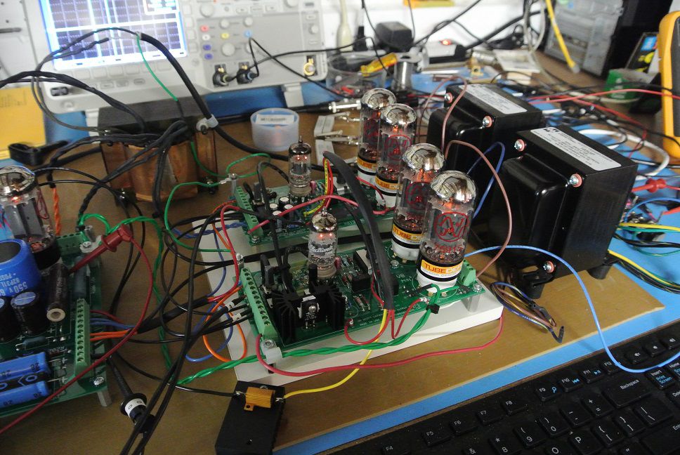
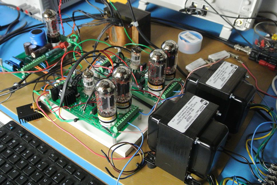
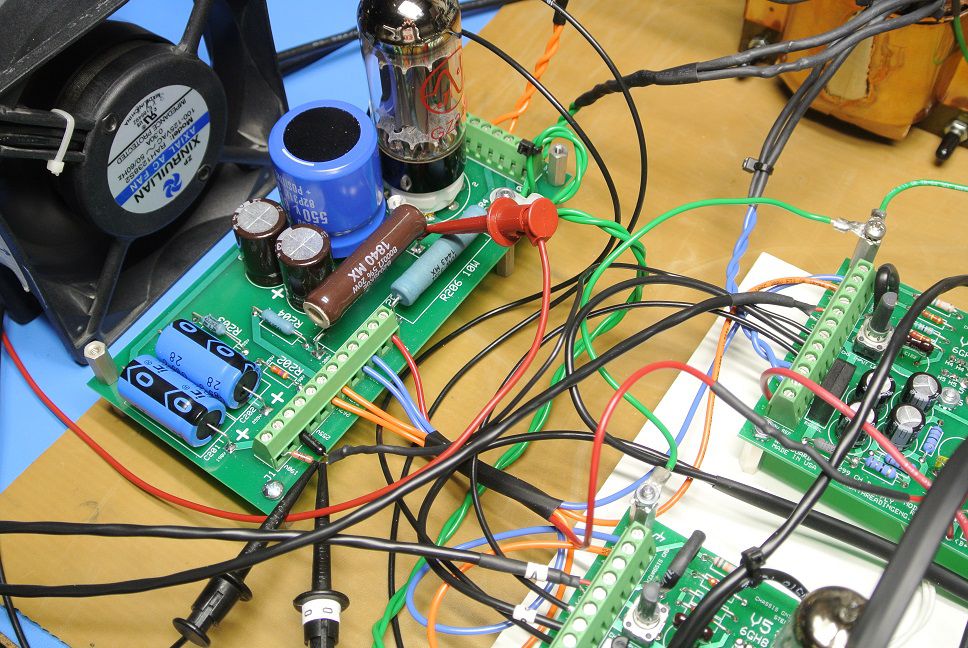
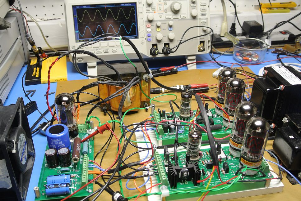
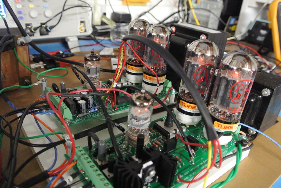
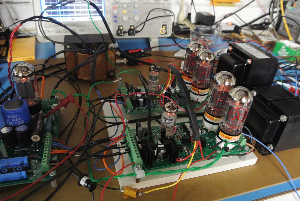
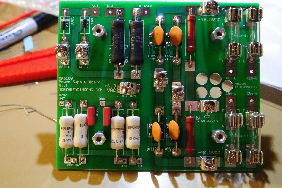
Completed the power modules and HV supply for the LK-72A clone amp. Lots going on here but so far, after 4 hours of swept sine cycling from 0.1 to about 40W/ch, nothing has burned, smoked, caught fire, changed color or melted. Running the OEM output transformer against a Hammond 1650P. I developed the PC boards from the Scott schematic. This is the first iteration of the amplifier. I will redesign the entire amp after this one is completed.
-
Type A Crossover - Capacitors in series?
John Warren replied to Robbie010's topic in Technical/Restorations
LK-72A preamp section with models for the 12AX7 preamp tubes:
-
Type A Crossover - Capacitors in series?
John Warren replied to Robbie010's topic in Technical/Restorations
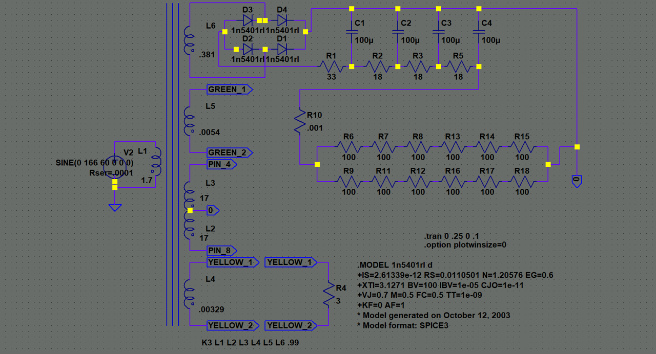
A transformer with one of the secondary's loaded to estimate power requirements for the devices:
-
Type A Crossover - Capacitors in series?
John Warren replied to Robbie010's topic in Technical/Restorations
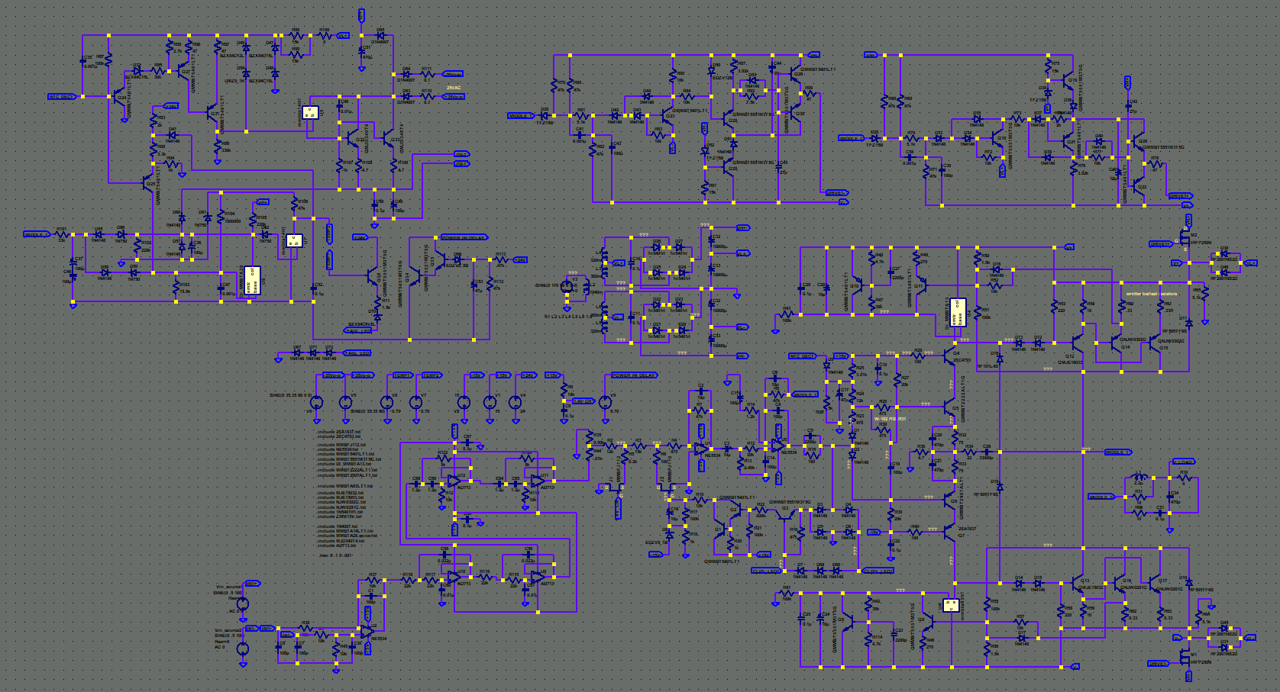
Crown XLI1500 with a built in active filter
-
Type A Crossover - Capacitors in series?
John Warren replied to Robbie010's topic in Technical/Restorations
Learning LTSPICE is simple, it's developing the circuits that takes time. If you'd like I show you how it can be used but on my site. I'll put a forum up called LTSPICE and we can noodle it there. Some examples of models: Crown D45
-
Type A Crossover - Capacitors in series?
John Warren replied to Robbie010's topic in Technical/Restorations
That's because it's not a Transformer it's an Autotransformer. Autotransformers have only one winding and in the case of the little model I posted, it's only the -3dB tap. -
Type A Crossover - Capacitors in series?
John Warren replied to Robbie010's topic in Technical/Restorations
FFT at the same location as Tap_4_-3dB. Photo of test setup: http://www.northreadingeng.com/Audio/group/viewtopic.php?f=12&t=10 If you want to continue the discussion please log into my site otherwise cheers!