
John Warren
-
Posts
2262 -
Joined
-
Last visited
-
Days Won
1
Content Type
Forums
Events
Gallery
Everything posted by John Warren
-
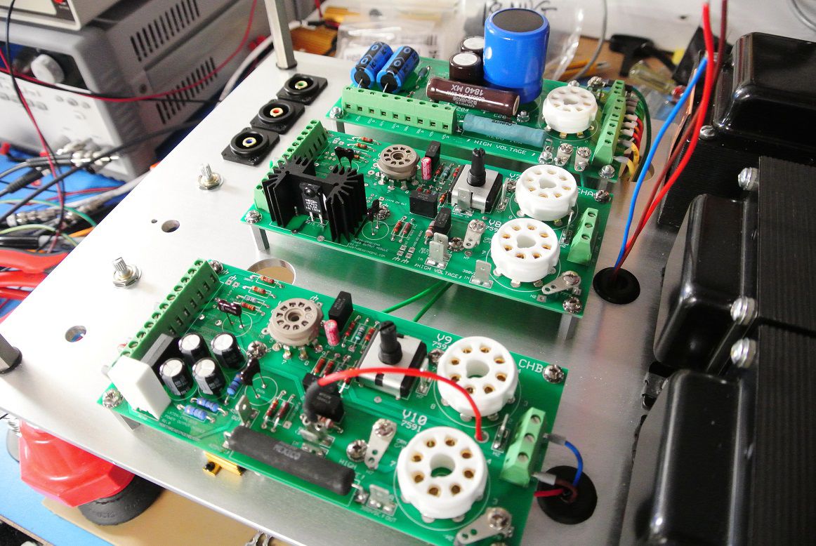
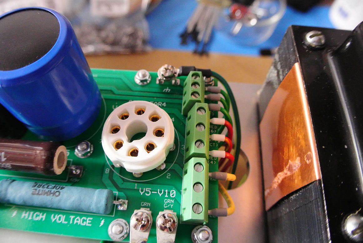
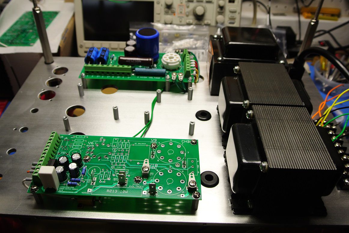
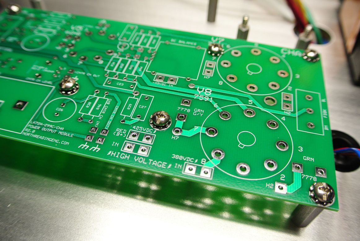
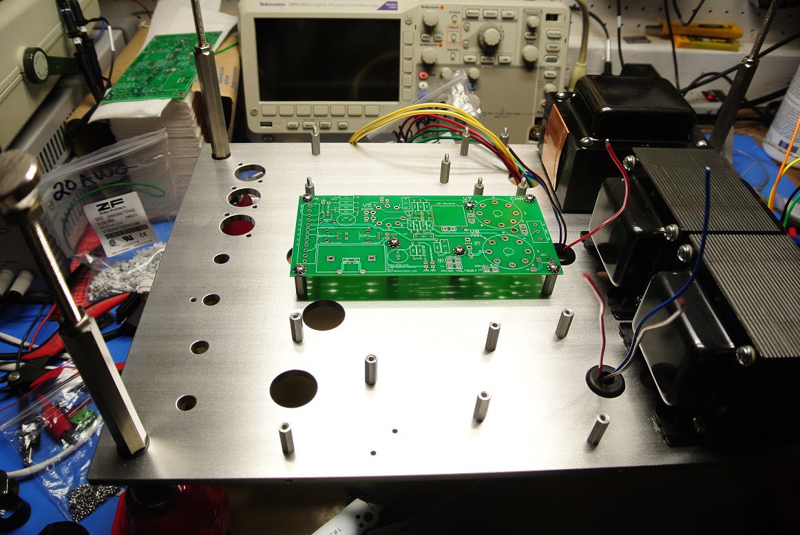
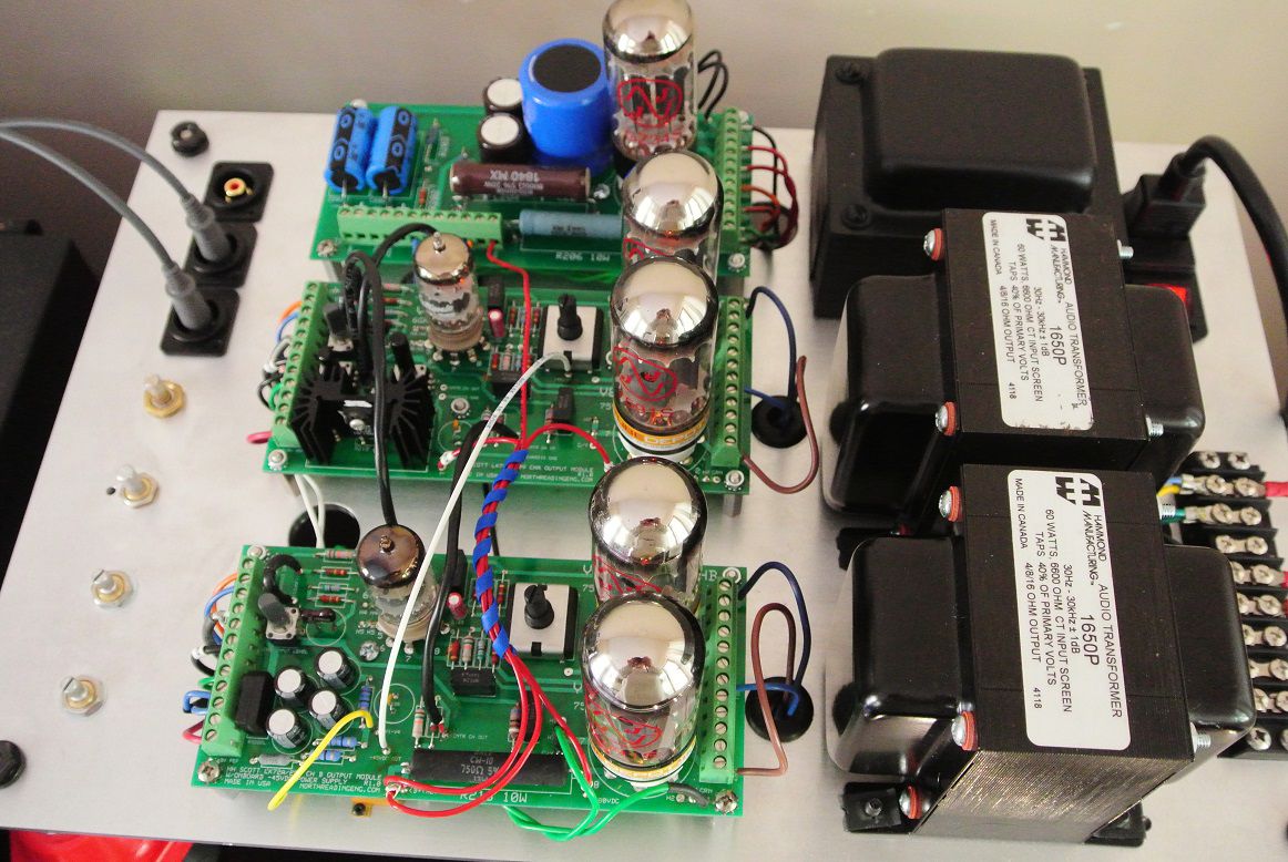
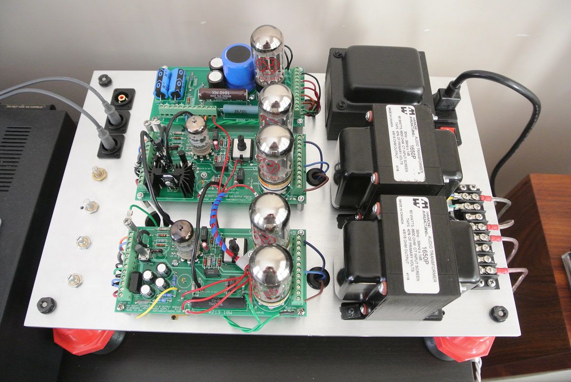
Thank you all for the comments, I'm glad a few of you find it of interest. The first iteration of this thing, posted earlier in the thread, was to determine if the basic layout of the components produced a low noise, hum free amp that could operate reliably for 100s of hours of operation. Here, a few revisions were baked in but the overall layout works well so I didn't change too many things with this go. Completed the CHA and CHB boards. Next step is wiring it up. There are three returns back to the HV supply card (green leads below), each lead sinks return currents from CHA, CHB and bias supply star grounding traces back to the center-tap. The HV supply utilizes it's own star grounding as well. Every component with a return back to center-tap has its own return to the center-tap which took some time to layout. I'm a fan of the AMP Faston connectors, they make w-t-b connections simple to enable. Purist would prefer solder but I'm not into making life miserable for fly-shit. On these units, I'm using the Scott replacement output transformers from Transcendar so I should be able to use the same feedback circuits as the factory originals. That was not the case with the earlier build using the Hammonds. A tweak might still be necessary. I use a couple for ferrules depending on the connection. Here I used the this one ($120USD) made by Zoller + Frolich (Crimpit F 6 L).

-
My take, Tektronix oscilloscopes of the mid 70s vintage were the last generation of instruments designed around discrete devices. When you peek into a vintage Tek scope you see pretty quickly they represent an incredibly high level of design sophistication. The engineering, the supply chain and the industry as a whole had matured to a point where they were not going to get much better without a significant engineering breakthrough. That "step change" was leveraging integrated circuits. The point however is that discrete device designs, given where the technology was, were very effective at solving the problems oscilloscopes were used to solve at the time. They worked and they worked well. When ICs were used, bandwidth went up, signal to noise went up and the improvements were obvious on the screen of the scope. Analogous to the Tek example, tube amp design, manufacturing and the tube supply chain were, by the late 50s, mature, there was no place to go. And, they were making very good sound. Then low cost transistors appeared. Distortion went down, signal to noise went up and the improvements were obvious to measure on FFT and distortion analyzers. What hasn't had a step change is the loudspeaker and the basic loudspeaker of 2020 isn't that much different than the ones made in the 50s. Materials are better and magnets can have insane BL-products for a given magnet volume but they're only evolutionary changes, not technological "pivots". Unlike the oscilloscope example the audio signal path "ends" using a device invented in the 1920s and refined largely to a point where it's a bit better than where it was in the late 1970s. So yes, it's easy to measure differences between transistor amps and tube amps on distortion analyzers loading each with a resistor load. But the end of the signal path is not a resistor, it's thing called a loudspeaker, an electromechanical device that has mass and presents a reactive load to the amplifier. And, it can take the most sophisticated, electrically engineered audio amplifier made today and send it back to 1975 or even 1955 if you're using an EV Patrician let's say. So that's why tube amps still "work".
-
That's actually 100mA, so plenty to stop your heart.
-
Getting back to my initial question. I suspect that the risk of lethal shock, though quite real at 500VDC, is in fact lower than what theory would suggest. In other words, most shock events at 500 VDC deviate sufficiently far enough from the conditions required to cause a fatality. Now 1kV and higher is a different kettle of fish.
-
There's a very real possibility of lethal shocks working with or tweaking a tube amplifier. In HiFi, they've been around for over 70 years and, combined with musical instrument amps, 10s of millions (if not 100s of millions) manufactured and distributed throughout the world. And even today they're still popular and in wide use albeit amongst a niche group of audio and musician types. And then there's kits. You'd think that death by electrocution would be a running plague associated with tube amps but I don't see it and find that a bit curious. Thoughts, comments?
-
What are the advantages?
-
Just use it and enjoy it. When it craps out then think about getting it fixed.
-
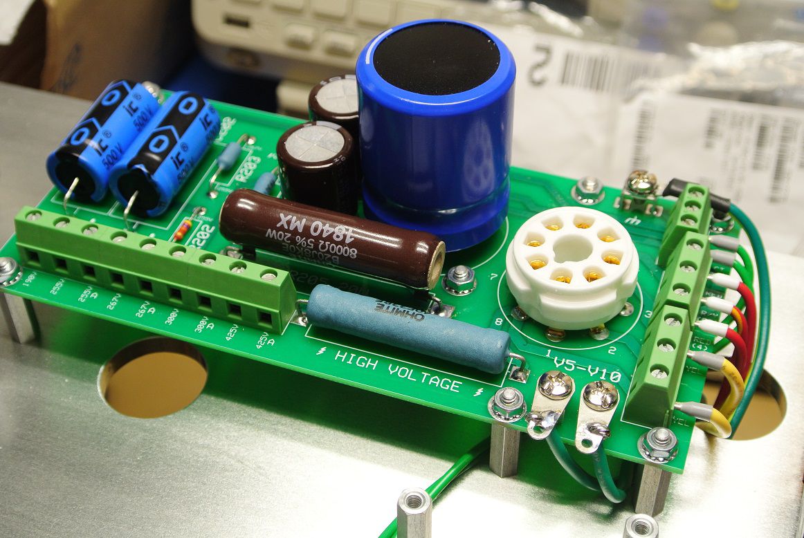
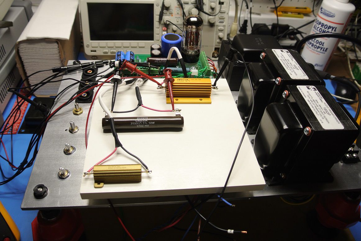
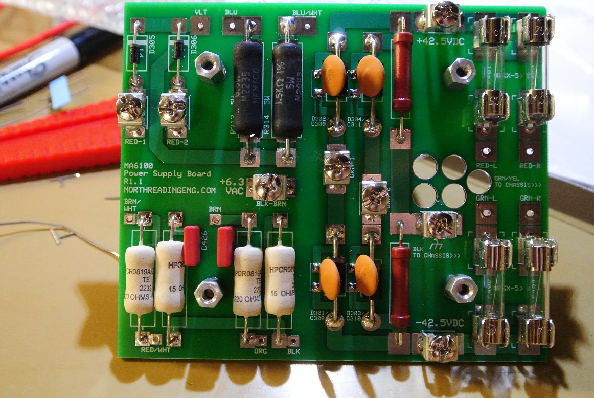
Thanks. Took about 4 hours to build what's shown below including testing the HV outputs. There are five HV rails. To get the module good and hot, ran them into resistive loads for about an hour at 125VAC input. Draws about 1100mA. B+ at 125VAC is about 460VDC. Uses 5AR4 rectifier, which I have many.
-
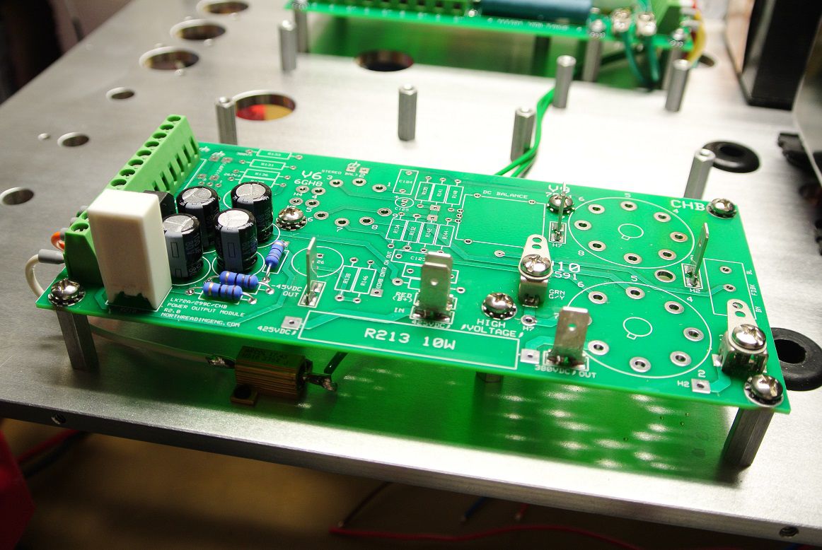
CHB output module is next up. I didn't get much further than getting the Fastons soldered in. Completed the -45VDC bias and preamp filament supply. The 299C and LK-72A both use a separate bias winding off the power supply transformer to provide AC voltage to the supply. That's nice.
-
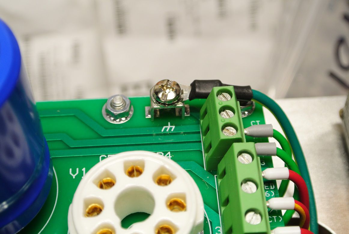
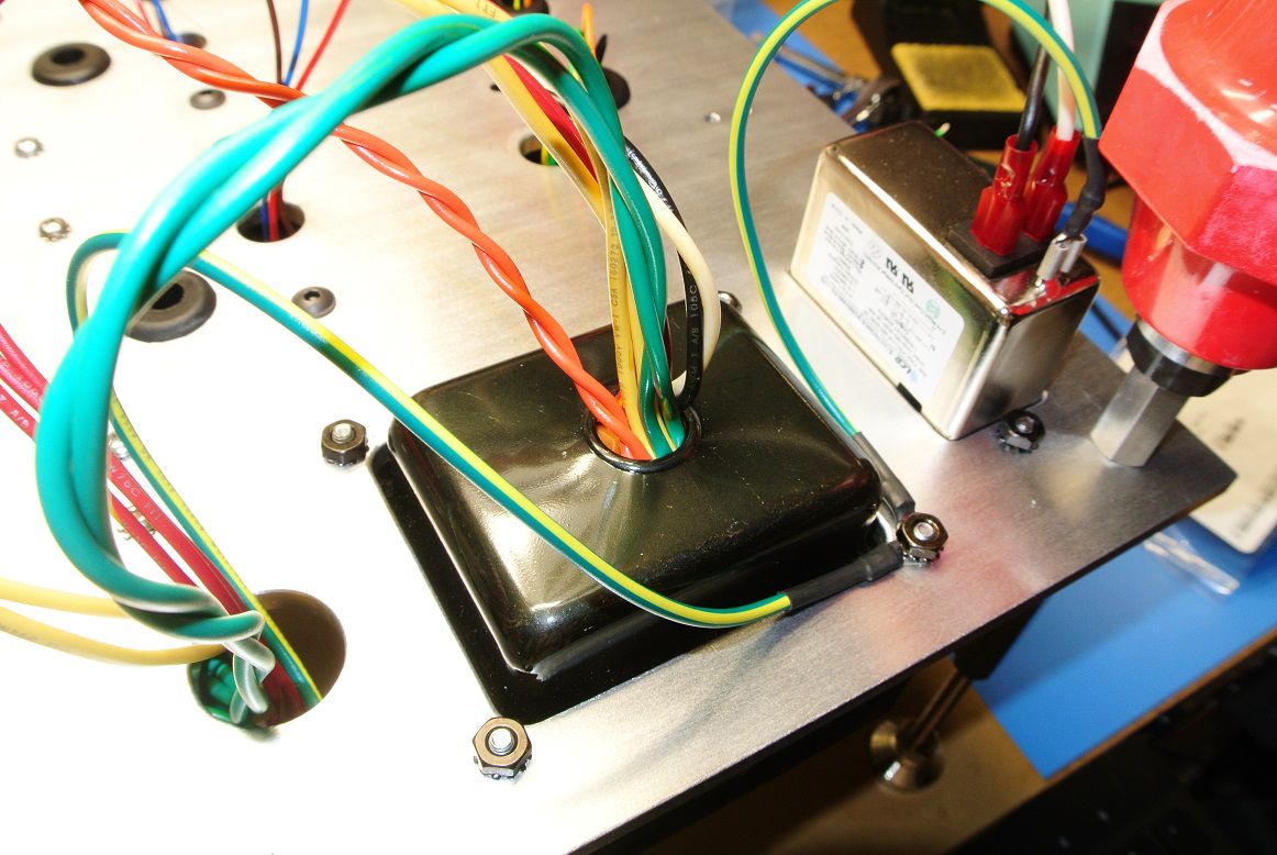
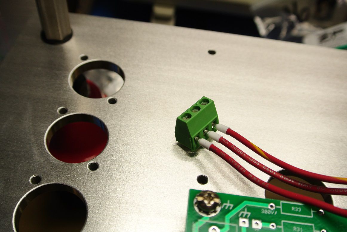
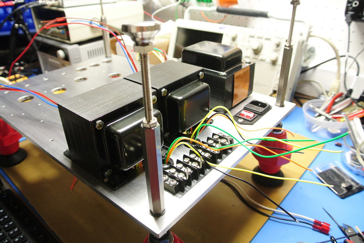
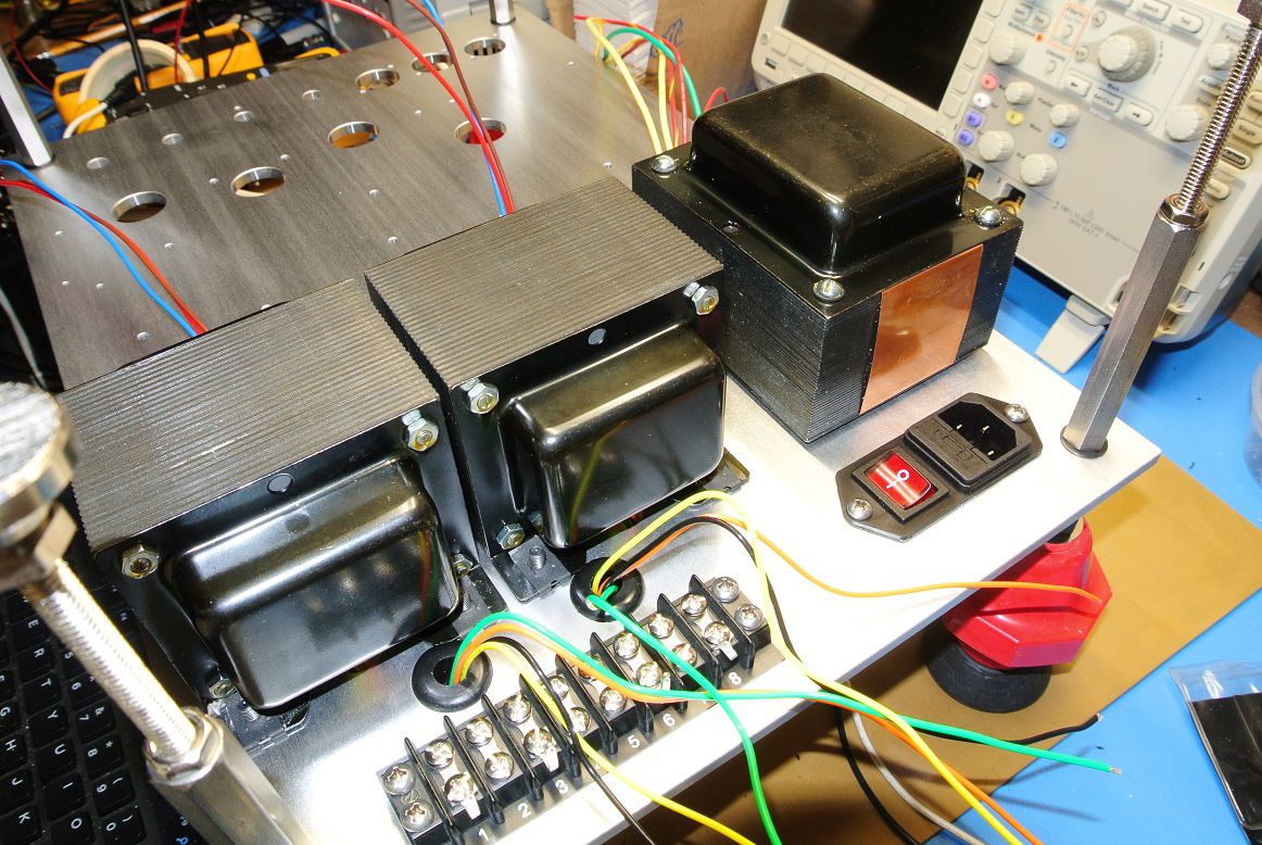
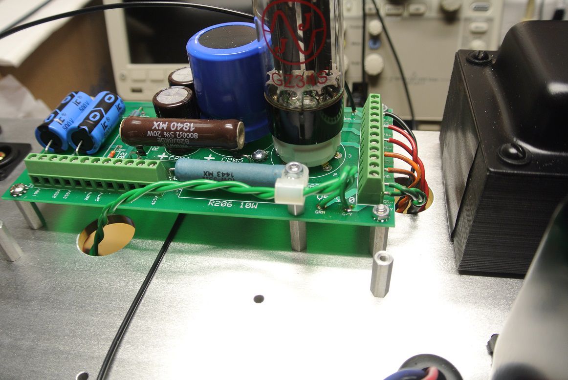
Continuing on with the second iteration of the amplifier. The high voltage board terminals are now 600V Phoenix type. A dedicated terminal block ties center-tap leads from the CHA and CHB output modules back to common junction which then ties to chassis ground and the IEC grounding lug located on the filtered AC intro module. AC filament power now comes from Keystone terminal lugs. The large cap is a screw terminal type that allows for easy field replacement.
-
Are these the www.dynakitparts.com or does the Bob Latino sell another version? If no, why go thru a reseller.
-
The long awaited "Little Sweetie" mono SETs
John Warren replied to tube fanatic's topic in Talkin' Tubes
Are you isolating the power supply transformer from chassis ground? -
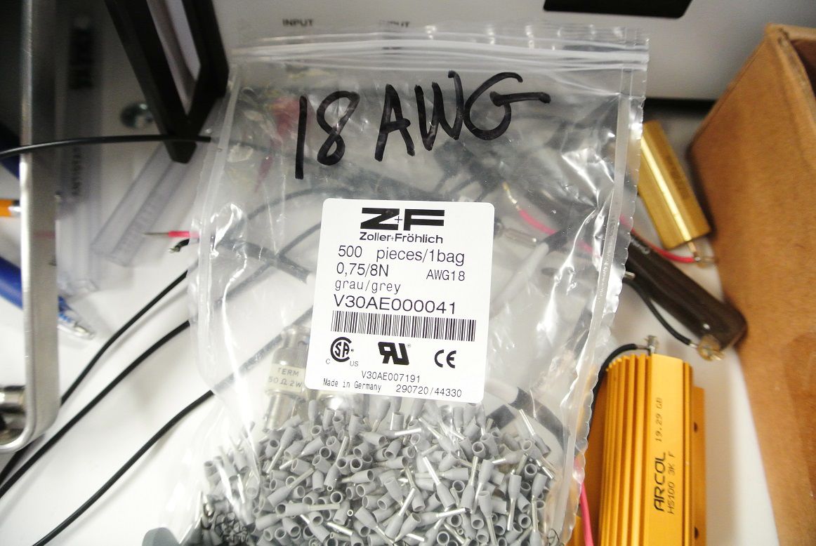
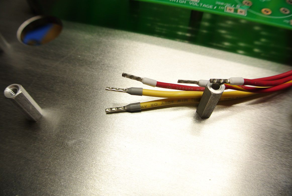
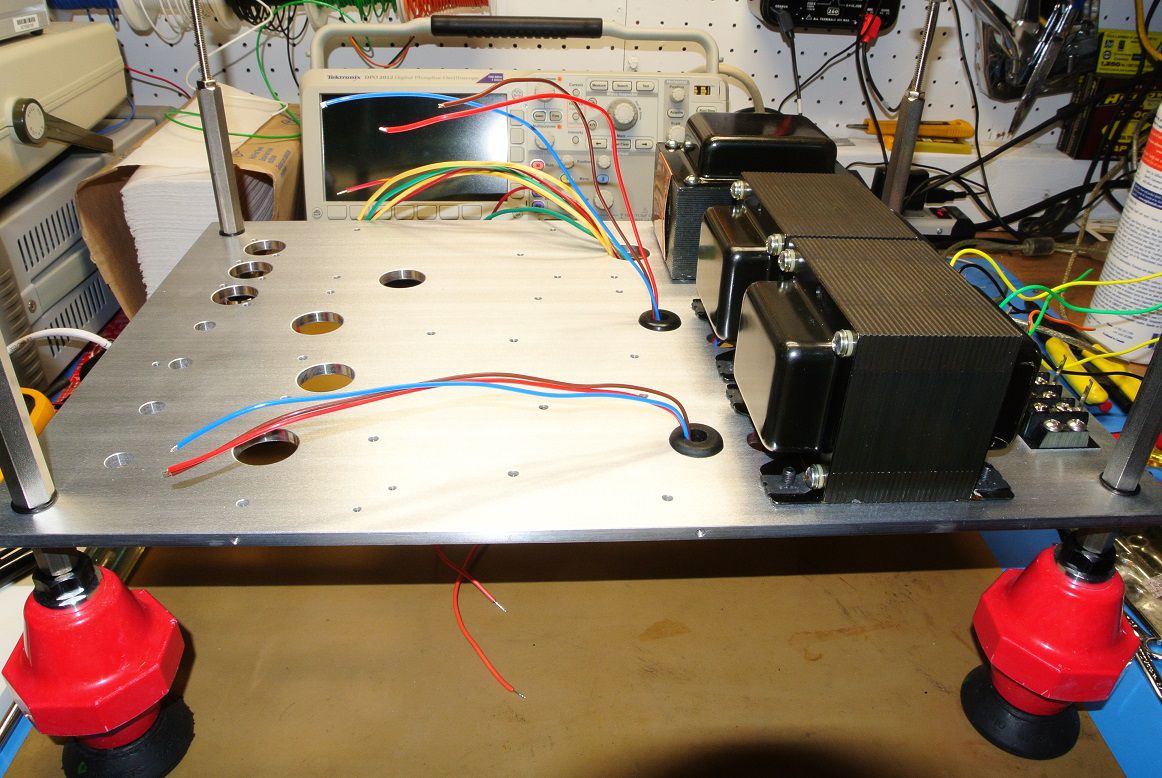
For the second iteration of the amplifier revisions were made to improve build quality and simplify the assembly. I've become a big fan of German Z&F ferrules for wire termination so those will be used for terminal block connections. The crimping tool is a bit pricey at $240USD but lower cost ones can be found that do the same thing. The higher cost units have interchangeable dies and are certified to crimp per a particular industry standard (DIN, CE, UL, etc). The first two amplifiers were built using 400VDC Phoenix terminals and hook-up wire which doesn't cut it for voltages that exceed 460VDC at 125VAC input. The revision will use 600VDC terminal blocks and Silicone insulated hook up for all +400VDC wiring. The wire to board connections will allow removal of the board without having to de-solder and the boards were revised to accept AMP 250 Fastons (both flags and verticals) and 7778 screw connect wtb terminal lugs for filaments. And if they're good enough for the McIntosh retro MC275..... Simple 2-layer boards made is USA! . The remaining hardware is due in this week.
-
Primary impedance presented to the P-P plates using the Transcendar output transformers shown below. The OEM transformer is BLUE. Some differences but I'd be hard pressed to hear them using the 7591 output tubes.
-
The Transcendars output transformers are excellent replacements. The bandwidth measurements are below. The OEM transformer is in BLUE. The Green and Dark Red traces are the two Transcendar units. Takeaway is the Transcendar replacements exhibits the same bandwidth. Load is non-inductive 8-Ohm. Analyzer is set at 194kHz sampling.
-
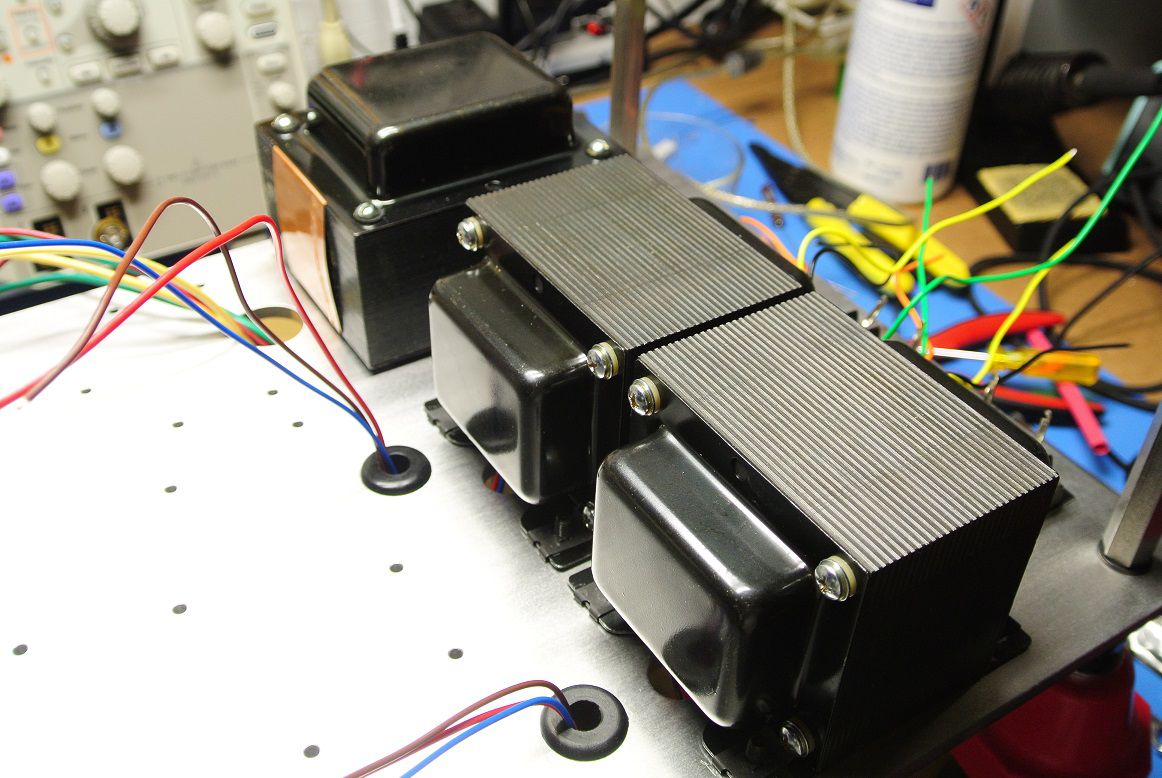
Starting the second build of the LK72 amplifier. The replacement Heyboer PS transformer and Transcendar output transformers are being used in this build. The Heyboer transformer is a substantial transformer, a superior embodiment of the OEM hardware.
-
Chassis cage attached on the Alpha. Next iteration of the amplifier (i.e. Beta) will have the Transcendar output transformers and the Heyboer power supply transformer. And of course, the performance will be measured and posted here.
-
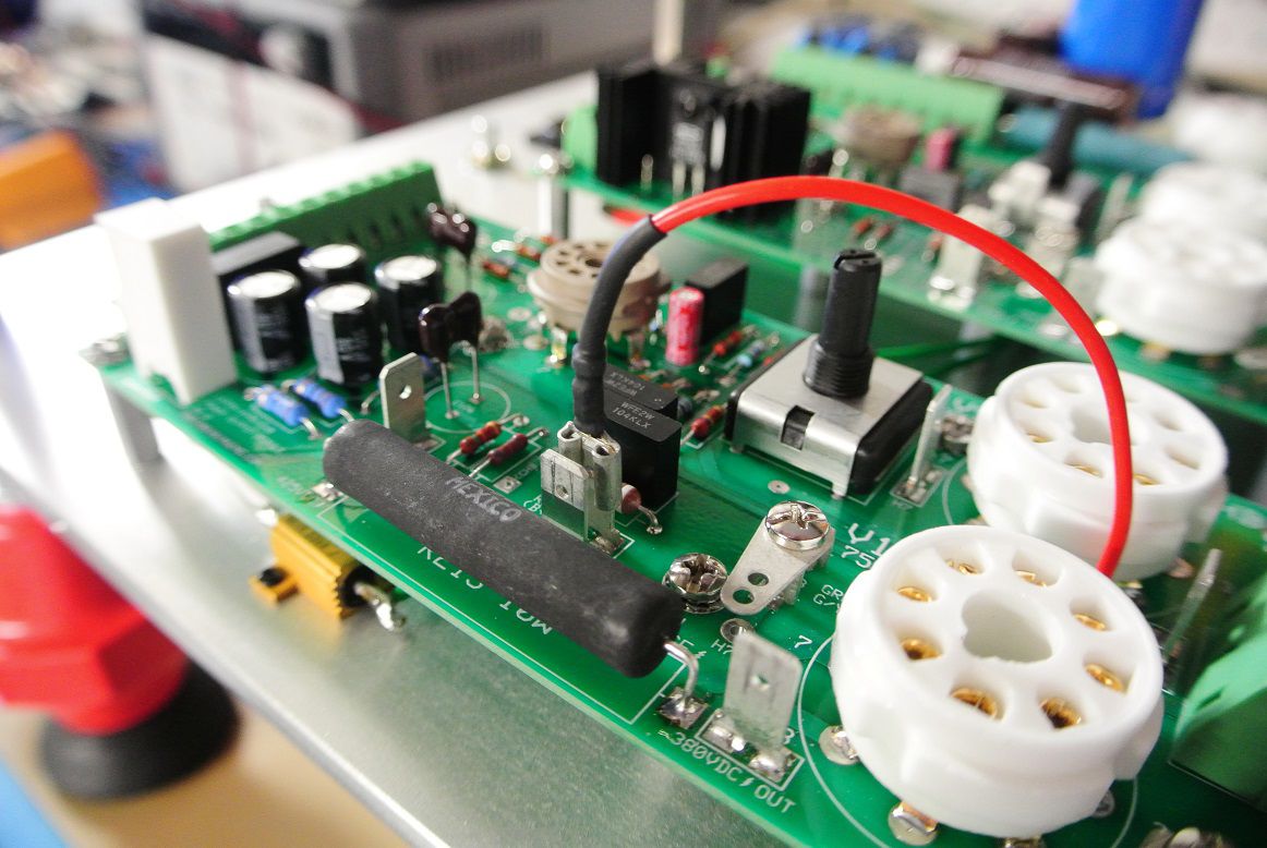
Presume you're referring to the blue, spiral-wrap bundle. Those are B+ leads and 380VDC screen voltage for the 7591s. The white lead is -45VDC for DC balance pots sourced from the on-board -45VDC supply. That supply is capable of driving numerous 12AX7 preamp cathodes, the bridge will provide about 2FLA if not limited by upstream fusing. The HV supply has both 190 and 255VDC rails to drive the LK-72A preamp section. A second iteration of the amplifier (which will be going to a customer) will have a few hardware and PC board tweaks including 600V barrier terminals, Transcendar 299C replacement output transformers (better bandwidth than both the Hammonds and the original Scott units) and a new Heyboer power supply transformer. The Heyboer transformer is a very well made unit (NOS valves to thank there). The original LK-72A/299C amplifier is, of course, not grounded to the Earth connection by the power line plug. So this needs to be considered. Center-tap drains are star-configured on all three boards, which is a painful routing exercise given the mix of high current AC, HV DC and low voltage, high current DC leads on each board. The stair "point of contact" from each power output board returns to the IEC ground prong via dedicated, 16 AWG leads soldered to the Earth prong tab located on the AC housing module (i.e. no isolation). The negative screw terminal lug on the blue, big-*** cap located on the HV board is tied directly to the center-tap which is also tied to the center-tap drains of the output boards. There's also a chassis ground on each board which drains small signal ground sheaths (only) to the chassis which is then tied to the ground prong through the AC input module which has, in addition to fusing, has an internal line blocking filter that eliminates powerline artifacts and protects the circuits from surges.
-
Thank you gents!
-
Thank you.
-
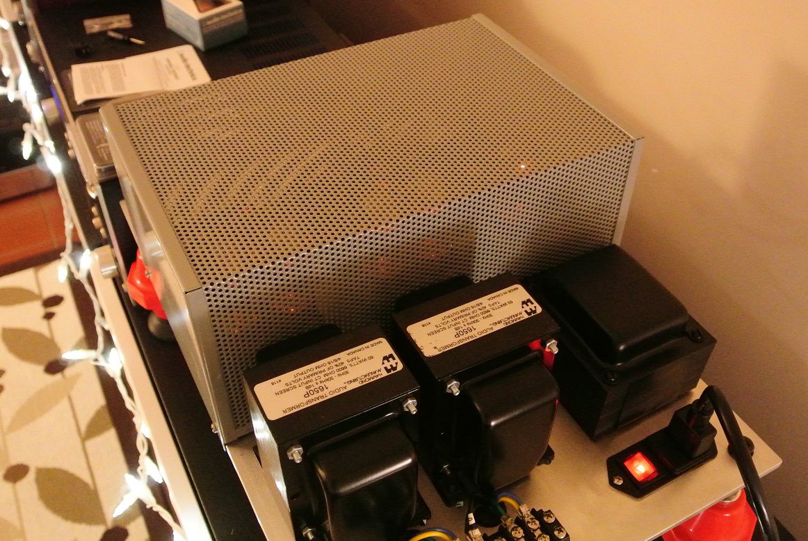
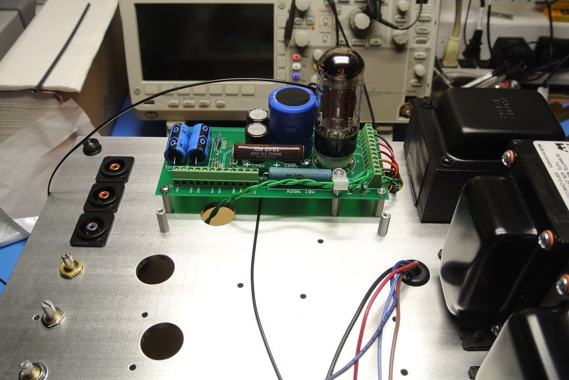
So, this is what it looks like off the bench and running. I have a cage that covers the entire set of boards but it needs a few holes drilled in the top to allow the DC balance to be adjusted. I'll grommet the holes and install fiberglass shafts to allow adjust whilst operating. I posted a few more photos in the "show us your tube amp thread".
-
Output module boards installed and running hard sinewave sweep at full power looking for trouble. While running there was a power failure, neighborhood wide. I thought for a second my little amp pulling a MASSIVE 1450mA brought the local grid down! What was nice, the power cycled back on a second or two after and the amp fuse tripped nicely (2FLA slow). I use an autoformer with a 3A fuse installed to feed the circuit.
-
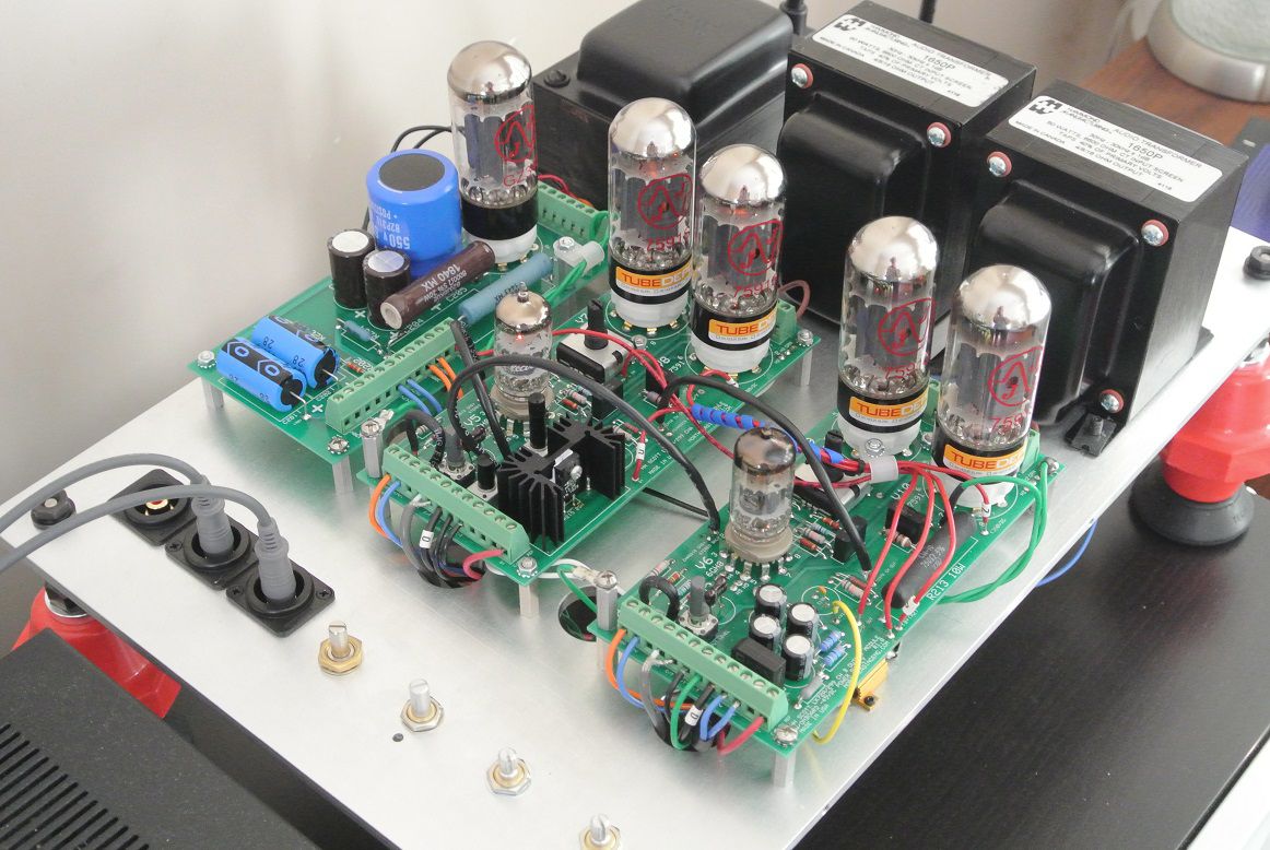
My clone of the Scott LK-72A amplifier section with the cage removed. Needs a nice wooden plinth. I have a pair of the Scott LK72A/299C output transformer replacements from Transcendar and will swap those in after spending time with the Hammonds. The Hammonds are a wee bit oversized for the power levels but I had them lying around so why not. Compensation needed some tweaking with the Hammonds. Also, the original design used silver mica in the FDBK return which I had a bit of a time with. For some reason, which I'm still noodling, MLCC provided much better stability based on the analyzer response. The amp is insanely quiet. Spectrum analyzer shows flat well out past 50kHz. If there's ever another Pilgrimage I might be tempted to drive this thing and a modified version that's almost complete down to Hope so we can all listen, compare, contrast.
- 881 replies
-
- 10
-

-

-
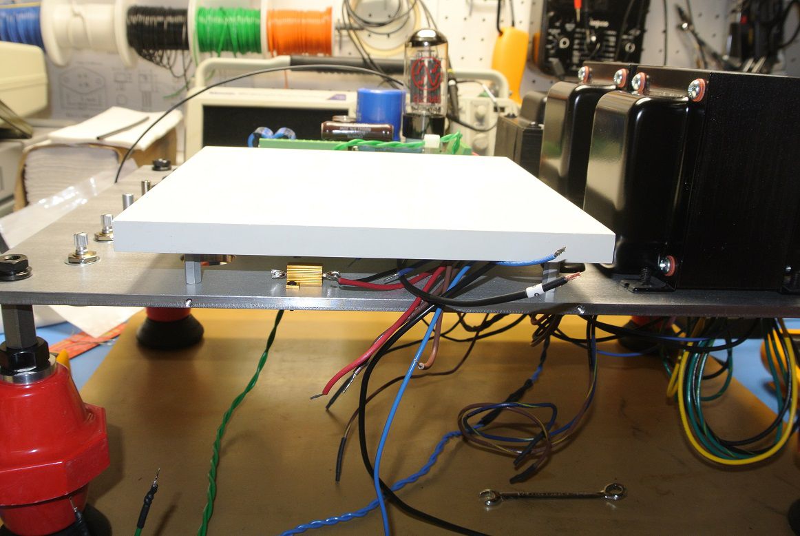
Boron Nitride plate used for load testing the HV supply. The loads get pretty hot!
-
Also installed the HV supply board.