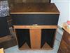
tom b. 57 Posted July 8, 2012 Share Posted July 8, 2012 I have been given a pair of these drivers mounted on metal horns from a friend who wishes to sell them. They are 16 ohm 20 watt drivers. I can't find any info. on them. I am hoping that someone here can shed some light on what speakers they were used in, what years they were manufactured and some specs. Anybody have any experience with these? You guys have always came through for me when I have asked questions about drivers and speakers before, and I am very appreciative of that. Thanks in advance, Tom Quote Link to comment Share on other sites More sharing options...
Guest " " Posted July 8, 2012 Share Posted July 8, 2012 I have an old atlas sound catalog that shows it as a 20 watt driver, 125db, 120 - 7000 hz. The same catalog shows the PD5HV running from 80hz to 12000hz so I would put those 120 - 7000hz response spec's as suspect since today the PD5HV is only rated to 4100hz. Quote Link to comment Share on other sites More sharing options...
djk Posted July 9, 2012 Share Posted July 9, 2012 The original driver specs are stated on a 6' air column are the -10dB points of the response. 1 Quote Link to comment Share on other sites More sharing options...
tom b. 57 Posted July 9, 2012 Author Share Posted July 9, 2012 The original driver specs are stated on a 6' air column are the -10dB points of the response. Please interpret. I am not sure what this statement means. Quote Link to comment Share on other sites More sharing options...
djk Posted July 9, 2012 Share Posted July 9, 2012 If you don't know what 10dB down means I can't help you. What do you think a 6' air column means in this context? Maybe a horn? Maybe 6' long (unfolded)? Quote Link to comment Share on other sites More sharing options...
tom b. 57 Posted July 9, 2012 Author Share Posted July 9, 2012 If you don't know what 10dB down means I can't help you. What do you think a 6' air column means in this context? Maybe a horn? Maybe 6' long (unfolded)? I know what 10db down means, but the 6' air column threw me. Thank you for enlightening me on this. I have very limited technical experience, practical or acedemical. Forgive me my ignorance. Tom Quote Link to comment Share on other sites More sharing options...
WMcD Posted July 9, 2012 Share Posted July 9, 2012 A plane wave tube is used to measure the actual acoustic power output of a compression driver. I don't find a diagram on the web tonight, but it must be in cyberspace someplace. We'd like a perfect resistive acoustic load. So the business end of the driver is hooked up to a tube of the same diameter. Also, there is a sort of T connection to the tube near the driver end. A microphne is placed there for measurement. In theory, the wavefront moving down the tube from the driver is flat, and thus a plane wave. To make a measurement the audio input is swept through a range of freqs and the electrical output of the microphone is graphed. You get the actual acoustic response or output of the driver. If you look at some specs of Atlas drivers for example, you'll see that the electrical input power is 1 milliwatt (1/1000 watt), rather than the 1 watt typically used for speaker. This is because the microphone is right up near a very loud source (the driver). We have to reduce the electrical input so that the acoustic input to the microphone doesn't ruin it. Of course the tube must end someplace. There would be a reflection from the open end if we didn't do something. One technique is to place some acoustically absorbant material in the tube itself. Why is this a good way of measuring? It is because we do not have the effects of real world finite horn. Horns only present a near perfect (resistive load) at at a freq about 1.4 times their cut off freq or Fc. Below that they start not presenting the perfect load. Also, all but constant directivity horns narrow their pattern at high freqs. This gives what I call, the Maglite effect. If the beam narrows, the intensity or gain on axis increases. Again, look at testing conditions when a spec sheet shows some response curve. Often you'll see the response when the driver is mounted on a given horn, with the microphone at a distance of 1 meter. Nothing wrong with this IF that is the horn you are using. But because of the narrowing, the high freq end tend to be better than on a plane wave tube. Also the low end may be dropping because of the horn's Fc rather than the driver's output dropping off. The dB stuff is more complicated to explain, it is ratio and we use mathematical log functions. +3 dB stands for a doubling of power relative to some value, typically an average. - 3dB stands for half the power relative to the same. You'd think that when there is twice the power, it sounds twice as loud, but not so. Generally it takes 10 dB to sound twice as loud to our ears. Technically "phons." (It was Alexander Graham Bell who set up this system of analysis by ratios and established what is actually a "Bell" unit of ratio. That was a great amount and so 1/10th of it is used -- with 1/10 being a "deci" and hence deci-Bell or dB. When a unit is named after a fellow, the initial is capitalize. But I digress. Like kilo-Newtons or milli-Henry being mH) Historically, you'll see that speakers and some amplifiers are spec'ed saying that frequency response is over some range of freqs (e.g. 50 to 15,000 Hz) in a window of plus or minus 3 dB. So there are wiggles in there. If the spec is plus or minus 5 dB it shows that the response is in a wider window and not so "flat." There are more wiggles or variation in the window. WMcD Quote Link to comment Share on other sites More sharing options...
djk Posted July 10, 2012 Share Posted July 10, 2012 Fig.5.10C is what Atlas was referring to on their old spec sheets. The impedance variations give you an idea of the response of the horn. A 2:1 ratio (like Fig.5.10C) implies peak-to-trough variations of about 6dB. Most commercial horns would have been more like Fig.5.10B, very large swings in the response. These show how well the horn loads the driver, those swings below zero are bad news. To get an idea of the response without an actual graph you would need a terminated tube graph, and a directivity index plot for the horn too. Quote Link to comment Share on other sites More sharing options...
tranny Posted July 10, 2012 Share Posted July 10, 2012 Thank you for the training, I learned something interesting. Bill Quote Link to comment Share on other sites More sharing options...
tom b. 57 Posted July 10, 2012 Author Share Posted July 10, 2012 Thank you guys for the information. This certainly helps me understand how these measurements are achieved and used for applications. Tom Quote Link to comment Share on other sites More sharing options...
WMcD Posted July 11, 2012 Share Posted July 11, 2012 Ahhh, found something. Attached is JBL's description of what is going on. A diagram of a plane wave tube is on page 3. WMcD JBL re plane wave tube and testing.pdf JBL re plane wave tube and testing.pdf JBL re plane wave tube and testing.pdf Quote Link to comment Share on other sites More sharing options...
Arkytype Posted July 11, 2012 Share Posted July 11, 2012 Here are a couple of images of the plane wave tubes at Hope & Indy. Quote Link to comment Share on other sites More sharing options...
Arkytype Posted July 11, 2012 Share Posted July 11, 2012 The first image is at the labs at Indy and the second is at the lab in Hope. Note the 1/4" microphone and cable on one of the Hope PW tubes. If memory serves me correctly, the PW tubes at Hope are filled with tapered open cell foam. The far end of the tubes are connected to a sealed box probably filled with foam. Lee Quote Link to comment Share on other sites More sharing options...
tom b. 57 Posted July 15, 2012 Author Share Posted July 15, 2012 Thank you guys for all the help. The JBL document and pictures of the Plane Wave Tube are very helpful in my learning. I actually now know and understand the testing method for the drivers. This is why I love this place. Tom Quote Link to comment Share on other sites More sharing options...

Recommended Posts
Join the conversation
You can post now and register later. If you have an account, sign in now to post with your account.
Note: Your post will require moderator approval before it will be visible.