mikebse2a3
-
Posts
4825 -
Joined
-
Days Won
1
Content Type
Forums
Events
Gallery
Everything posted by mikebse2a3
-
Behringer DEQ2496 Ultracurve Pro Equalizer
mikebse2a3 replied to mikebse2a3's topic in Technical/Restorations
Thanks Colin and Daddy Dee for the responses. Well curiosity got the best of me and I called around to see if I could find the EQ. Found it at Guitar Center and they said I could try one for 30days so I figured it was time to try one for myself since it had been many years since I had tried EQs without much success. I just felt I had reached the limits with setup and room treatments(and yes these need to be done as much as possible first before EQing) and it was obvious to me that the room was still just throwing the system way off balance. I can tell you already that it will be staying in my system. Just beginning to learn to use all its options but it has already adressed some of the problems I haven't been able to solve completely.It has been an overall improvement.Every CD I tried was more listenable/musical which indicates to me a real improvement to the system/room. Clarity and Tonality were the two most noticable improvements. mike -
Behringer DEQ2496 Ultracurve Pro Equalizer
mikebse2a3 replied to mikebse2a3's topic in Technical/Restorations
Just testing this was second time in three days that the forum stoped letting me post giving me a banned warning.Is anyone else having a problem like this? -
Colin Said CDs certainly do have things musical below 40 Hz, no matter what the subject matter! I am using a Real Time Analyzer right now, the Behringer DEQ2496 UltraCurve Pro. Let me tell you, even the human voice has harmonics that extend below 40Hz. ----------------- I would like to hear Colin's or anyone with experience with this type of equilizers opinions on the benefits or any noticeable drawbacks to using one of these in their system. I've been working with room treatments for years and I've come to the point of thinking that if you have to work with less than ideal room sizes and shapes that after reasonable amount of room treatments that a modern type equilizer like this might be able to improve a system futher. I would love to try a Tact or similar but cost are still really up there. The price of this unit seems very reasonable for the features. Thanks
-
Looks like regular La Scalas so far that I can see. Maybe a anniversary model?
-
there is one on audigon http://cls.audiogon.com/cgi-bin/cls.pl?spkrfull&1107478616 Does that look like a regular AL-3 network? mike
-
My No. 79 Merry Christmas Everyone
-
Crossover region for K-77 / K-77M tweeters
mikebse2a3 replied to Erik Mandaville's topic in Technical/Restorations
Hey Erik EV suggest a minnimum for the T35 of 3500HZ and using a 12db crossover slope I believe with a 6db slope I would stay with a 5000HZ to 6000HZ crossover point. Also EV suggest long axis orientation od the T35 doesn't matter as much with a higher crossover point. mike -
I need to ask this question another way, I think....
mikebse2a3 replied to Erik Mandaville's topic in Technical/Restorations
Gil said: But, do they act like inductors when in a circuit of the type we're working with. That is to say with a load. The answer here is that most or all of the inductance effect disappears. This is because the magnetic field is coupled to the "other" windings which have a resitive, or mostly resistive load. This is the coupling from one set of windings to the other through the magnetic core. I checked out the roll off an AA type crossover at the midrange some years ago and it seems to be at or near what you'd expect. So the inductance in the autotransformer is not that much of an influence. I.e. it does not turn it into a second order crossover. ------------------------ Thanks Gil for taking the time to explain this. This was something that I never really tried to understand till Erik started working with the L-pad. So thanks Erik for giving me a reason to learn more! mike -
I need to ask this question another way, I think....
mikebse2a3 replied to Erik Mandaville's topic in Technical/Restorations
Hey Eric just to clarify my thinking on the L-pad/autoformer The only reason to use the autoformer with the L-pad is because with the L-pad wired in parallel with the squawker the impedance is closely maintained allowing the orginal designs 13mfd to be used( you were orginally looking for a way to add adjustment without changing any other componets).This allows you to be able to adjust the squawker level without changing any other parts of the network. To me this just allows you to basically tweek the orginal design and isn't really a draw back since you already own the autoformer where as if you were designing from scratch you would just buy a larger value capacitor but no need to spend the money on the autoformer and just use the L-pad.I think in your situation for now its a good and simple way to acheive what you set out to do. If you don't mind changing the 13mfd capicitor value then you can eliminate the autoformer and just use the L-pad. In another thread you mentioned something about a peak in the K55v driver. You've been around here so long I fell I'm probably mentioning things you alredy know but just in case: You probably know that the one with the push terminals is the one that suffers with the peak.The solder terminal one doesn't exhibit that problem.Any way if you do add a coil to roll the high freq. off in the squawker circuit maybe that will take care of it if you have the push terminal types. mike -
I need to ask this question another way, I think....
mikebse2a3 replied to Erik Mandaville's topic in Technical/Restorations
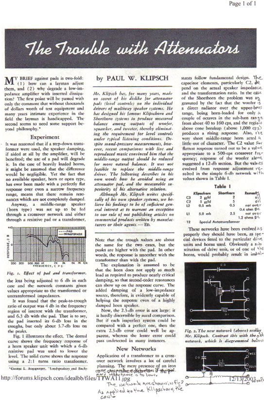
page 3 of article Eric You probably have already seen these articles like I had but it was good to go back and think about why PWK chose the methods he did at the time.I especially wanted you to see the crossover in FIG:2 with the .5mh coil(L2)like you had been thinking about. mike
-
I need to ask this question another way, I think....
mikebse2a3 replied to Erik Mandaville's topic in Technical/Restorations
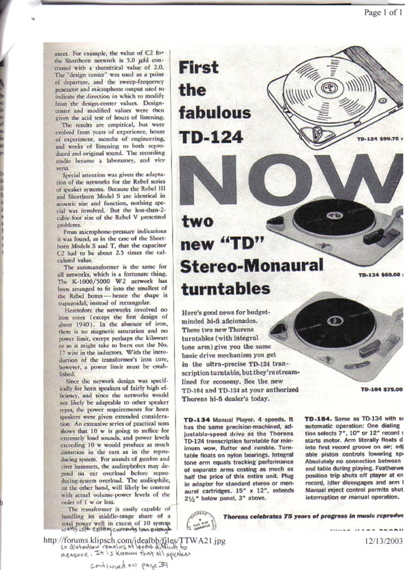
page two of the article for anyone wanting to read the whole article. especially notice the first and second paragraphs of PWKs steps to reach his crossover designs. mike
-
I need to ask this question another way, I think....
mikebse2a3 replied to Erik Mandaville's topic in Technical/Restorations
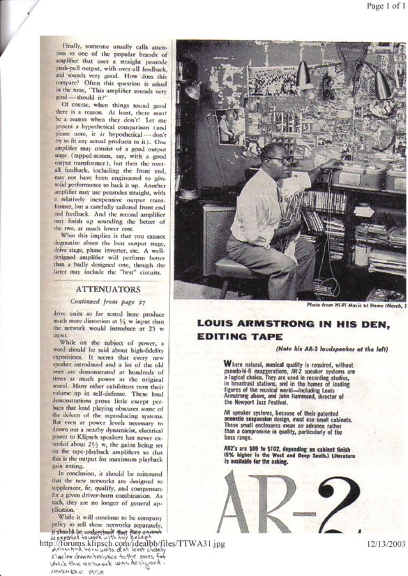
Here is a copy(not the best) of the first page of a article by PWK someone posted before. In the experiment he tells some of the benefits/reasons why he prefered the autoformer method over an L-pad method.Maybe both methods have merit(notice the AK-4 doesn't use the autoformer method but by all I've heard sounds very good) which when the total system design is taken into account one might be prefered over the other Eric: take notice of the network in fig. 2 notice the L-2 in the squawker circuit. Its listed as a .5mh so it looks like early on he designed a network with a bandpass section for the squawker. I can see two ways of thinking about being able to adjust the balance of a speaker systems. 1: (the ideal and prefered situation to me)It would be hard for us to balance a speaker better than a manufacture like klipsch who has the equipment,facilities and experience that the average person doesn't. So if we take this well balanced system and put it in a room and it doesn't sound good we are left with treating the room and setup to bring out the full potential of the system. 2: Most real world situations are that we are limited in being able to balance the room to the speakers needs and one reasonable compromise might be is to within reason be able to alter the balance of the speaker to make the best of the compromises we have to live with. mike
-
I need to ask this question another way, I think....
mikebse2a3 replied to Erik Mandaville's topic in Technical/Restorations
here is the second page mike
-
I need to ask this question another way, I think....
mikebse2a3 replied to Erik Mandaville's topic in Technical/Restorations
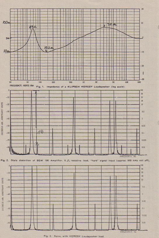
Here is the Dope From Hope paper for those that might not have seen it. At least in one instance PWK found a benefit for a rising impedance at least around this time in audio design. mike
-
I need to ask this question another way, I think....
mikebse2a3 replied to Erik Mandaville's topic in Technical/Restorations
Hey Eric First maybe Al will step in and give us a better understanding of exactly how the autoformer functions and its main benefits in this situation. ------------------------ No1: So, then I thought that the autoformer may also be providing the required inductance needed for this type of first order network -- which is why I was asking for the value of inductance between input tap 5 and output tap 4. -------- From my understanding(from reading the design papers of the ALK network)is the Klipsch A & AA networks don't actually roll the upper end of the squawker off they just let it naturally roll off.Where as the ALK and the type A network shown in another post I believe by John Albright is a true bandpass design for the squawker section that also controls the impedence caused by the autoformer as implemented in the klipsch networks designs by the use of the 10 ohm swamping resistor. As you probably know since the 10 ohm resistor is in parallel with the autoformer/driver part of the network it limits the resistance of this part of the squawker circuit to less than the 10 ohm value of the resistor where as the autoformer/driver impedence will increase with frequency without the swamping resistor causing the the driving amplifier to see a more complex impedence load versus say the ALK design. I remember seeing a paper by PWK about the varying impedance as not necessarly being a bad thing.(maybe I can find it and post it) Naturally the varying impedence will cause some amplifier interaction with the speaker/network causing some frequency response changes which a person might or might not like. The reason the klipsch network uses the 13mfd value is because that value is necessary because of the varying impedance of there network but if you compensate the network for the varying impedance(10 ohm swamping resistor) the capacitor value must change for the proper crossover between woofer/squawker. I see no reason why you can't select the coil and capacitor for a bandpass design with a L-pad. So my question to ALK or anyone else that has a good understanding of this is why is the autoformer better than an L-pad? Does it offer better coupling to the amplifier? mike ps: when you lift the ground side of the autoformer then you basically defeat its ability to attenuate the signal to the squawker.It my as well not be there at that point. -
Farewell type 'AL' Hello type 'A-LPD'
mikebse2a3 replied to Erik Mandaville's topic in 2-Channel Home Audio
Eric hopefully this is a resized picture of the AA to A with L-Pad picture you posted. mike
-
Multi-tapped input/output autoformer
mikebse2a3 replied to Erik Mandaville's topic in 2-Channel Home Audio
Dean said: I still wonder about what John Warren said back when I was playing with this. In effect -- that dropping the output of the squawker 3db by going to the #3 tap doubles the reflected impedance the 13uF cap sees by a factor of two. This supposedly reduces the crossover point from 380Hz to 160Hz. John said if you double the impedance the cap sees, you need to "half" the 13uF cap to keep the crossover point the same. Bob, I know you ran a plot on this that brought the math into question, but I did do more digging and it seemed to me that John was right. I don't think you can just arbitrarily move from tap to tap ------------------------------------- Hey Eric This is similar to what I mentioned in another post to you. It seems to me since the 13mfd cap isn't seeing the autoformer/driver impedance which was higher than the 16 ohm L-pad your using your electrical crossover point has shifted upward. The calculated impedance of the 13mfd cap at 400Hz = 30.612 ohm so if my thinking is correct the autoformer/driver impedance at 400Hz is also approx. 30 ohms. thus the approx. 400Hz crossover point. The calculated impedance of the 13mfd cap at 800Hz = 15.306 ohm so again if I'm thinking correctly with the 16 ohm impedance created by the L-pad your electrical crossover point has shifted to approx. 800Hz. One thought I have is if you used the L-pad after the autoformer your crossover point would stay pretty close to the design point but you would be able to reduce the output of the squawker.If you try this I would really be curious how this sounds to you. This might tell us if the sound improvement you've noticed is caused by the reduction in squawker level or as is probably the case also by the crossover shift and would it maybe sound better or worse if the electrical crossover point is maintained in your setup. I realize that where talking about a 6db per octave crossover in Eric's case so the crossover isn't as quick at dropping the output of the squawker as a higher slope filter would be and thus is more forgiving of this crossover shift but I believe it has to be a part of the differance in the sound as well as the level adjustment of the L-pad. Please don't take anything I'm saying as criticism of what your doing.I'm just really curious what all is really changing with this Mod. and I think it benefits everyone when we can understand why something has the effect it does which when it comes to things in audio "thats a real challenge".I realize you really like the changes you've made and thats what matters and I appreciate how you have been willing to share and discuss your ideas and experiances. mike -
Eric said: The way I did this was to take the L-pad body apart, drill a hole in the cent of the metal housing, did a little filing of the shaft, screwed the housing right onto the board in place of the autoformer, installed the actual L-pad back into the housing, and made the connections. -------------------- Hey Eric I'm curious now about this crossover configuration your running now. In your orginal post on the L-pad install you mention a AA-to-A network. So exactly how is your network configured and am I understanding correctly that you have actually replaced the autoformer with the L-pad. For some reason I thought you had installed the L-pad after the autoformer which wouldn't affect the crossover point very much if you used a 16ohm L-pad but would allow you to attenuate the squawker. What value capacitor do you have in the squawker circuit? Looks to me like it would take a change in the capacitor value to maintain close to the same crossover point for the squawker with the autoformer not in the circuit and dependent on the L-pad value. Anyway I'm glad you like this change but I'm trying to understand just what all has changed with this modification which if I'm understanding this right looks like the squawker's crossover point has changed as well as you being able to adjust the squawker level. mike
-
Hey Richard audioXpress magazine has a books page if you want to actually get deeper into understanding of vacuum tubes/amplifiers. http://www.audioxpress.com/bksprods/index.htm look under; Vacuum Tube Audio - REFERENCE they have two that I'm familiar with plus many more. The two I'm familiar with and would recommend are: Principle of Electron Tubes by Herbert J. Reich Radiotron Designer's Handbook by F. Langford-Smith (this is on a CD-ROM) Maybe some others around here can tell us about other good sources for tube info. mike
-
Richard try this site for some of your questions on tubes. http://www.thetubestore.com/index.html generally if your amp has bias controls for each output tube then matching isn't necessary but it can't hurt anything.If you only have 1 bias control for each channels set of tubes then you would want to replace the tubes with a matched set. If I had used tubes and one went bad I would probably prefer to replace them as a set with tubes of same type and similar amount of use. mike
-
Autotransformer/attenuation values
mikebse2a3 replied to popbumper's topic in Technical/Restorations
Bob My understanding from Stephen Phillips was the T4A is -4db. I learned this when changing my AK2 to an AK3 network in my Khorns. mike -
AA-to-A network with L-pad midhorn attenuation
mikebse2a3 replied to Erik Mandaville's topic in 2-Channel Home Audio
Shawn said: Actually the opposite occurs when you steer a center channel out. You reduce the comb filtering (frequency response interaction) between the L/Rs as they no longer reproduce as much of the same central material and it instead goes to a single speaker. Also because the distance between the speakers gets closer (between L/C and C/R) where they do comb gets pushed up to a higher frequency and becomes less audible. Hi Shawn! Good Point! Of course I was thinking of the center channel with the simple box and even though test might show lots of good/bad interaction our ear/brain is helped more with it than without it. I haven't tried a good processor like the Lexicon and am very interested in Erik's and your observations with it. I enjoy thinking about things like this then trying experiments and then trying to put those observations together to explain why I did or didn't hear what I expected. I often find myself with more questions than when I started. This Hobby is going to keep my mind busy well into old age!! mike -
AA-to-A network with L-pad midhorn attenuation
mikebse2a3 replied to Erik Mandaville's topic in 2-Channel Home Audio
Erik said: It's probably true, too, that careful measurement would reveal some oddities or other characteristics that might not 'look' so great on paper. However: I have no means to test our room response or sound quality other than my ears, which are of course ultimately what will decide on what sounds good or not so good. In this case, the 'good' brought about by the inclusion of a center channel is to such a degree that I have no intention of ever going back to two channels alone -- regardless of what theory or testing might disclose. What I have discovered is a sound so complete, lifel-like, palpable, etc. that it's almost uncanny! Last week I did an experiment where I turned the center channel off just after my wife left the listening room for a glass of water. When she came back, she looked at me, looked around the room, and said, "Did you do something?" "This sounds bad!" The sound she was referring to was the Klipschorns running by themselves in stereo-only mode. --------------------------- Yes Erik! Good test using the unsuspecting wife!! I do similar things with my girlfriend. I like trying something and then without telling her what I've done or what changes I've noticed in the sound I'll get her observation. Since she doesn't get into this critical mode of listening(which is something that at some point in the experiment I try to turn off and start listening more relaxed(natural)mode like at a real event) its a real help hearing her observations against my own. I believe just like you do that the ear will be the final judge! Even though their might be things that don't look good in a measurement the center channel is providing needed information that without it the sound isn't perceived as natural as when the center is providing this information. I(like you) am always trying things for the personal experience/knowledge that can be gained. Like I said I'll be very interested in your observations with the Lexicon unit. mike -
Hi NatGun I have a PWR transformer from a DH200 which I'm pretty sure is the same one the DH220 uses. The Transf. should be in good shape I had it left over after modifying a DH200 to a dual momo pwr supply. # on TRANSF. 464002 and 8318150 I believe the 464002 is the number to go by. The DH220 was basically a refinement of the DH200 circuitry and the amps where basically the same. You can have it for the cost of shipping if you want it just PM me with some contact info. mike
-
AA-to-A network with L-pad midhorn attenuation
mikebse2a3 replied to Erik Mandaville's topic in 2-Channel Home Audio
Hi Erik FWIW: One problem I've ran into with wirewound L-pads is over time the wiper contact can vary due to oxidation between the wiper contact and wire which just working the control from end to end will temporarly clear up.Yours look like really good quality and the ones I used where fairly good quality also but once they are set and not used over time the connection tends to oxidize over time since the cleanig action of using the control doesn't happen once a setting has been chosen.Maybe you will have better luck with them than I've had. I like to replace the L-pad with resistors. Once I've settled on the setting I'm going to leave it at. I just take it loose and measure it for the resistor values I'll need to replicate it with. I'm using the ALK crossover with the variable autoformer.Its really an interesting learning experience how just a small variance in the squawker setting will show up different things in the recordings by not just the tonal balance shifts but there is some masking effects that show up or nearly disappear depending on the settings.I've also noticed the same effects by how I use room treatments. The center channel speaker you been experimenting with also is an eye opener about how we hear. If you think about it, by adding the center speaker you are changing things more than a person might would think.You will be changing the first arrival times due to the different locations/designs of the speakers(The lexicon if it has center channel delay will change this to some extent and I will be really interested to see how this changes your perception of the sound). You will have constructive and destructive interaction between the speakers.The speaker room interaction changes also.What I've noticed so far using a center speaker is something more natural sounding especially on vocals happens even when the spread isn't very wide (the wider the spread the more obvious the benefits of the center speaker are). Thanks for posting all your experiments! mike