

boom3
-
Posts
1749 -
Joined
-
Last visited
Content Type
Forums
Events
Gallery
Posts posted by boom3
-
-
There is an installation by Dale Chihuly at the house.

-
 4
4
-
 1
1
-
-
A trip to Arizona to see old friends, also went to the top (as far as public access is allowed) of Mt. Lemmon and Taliesin West, the Frank Lloyd Wright home and studio inn Scottsdale.
-
4
-
1
-
-
17...yeah...I didn't realize that until later (bought used)
Excellent sound
-
Let's see...
1. Main system in living room theater uses four Cornwall IIs, a Klipsch-derived center, and a Rhythmik sub, in a 7.1 system (rarely used in that configuration)
2. My study, two homebuilt 12 inch Visaton woofers & PRs with Great Heil AMTs; hooked to the iMac and a disc player
3. Partner's study, Cambridge "Satellites and bass module"
4. Garage, two Minimus 7s driven by an old Pioneer and a Sony 5 disc changer from 1995
5. Car, 17 speaker system by Lexicon
-
2
-
-
-
-
2
-
-
I have four Cornwall IIs, and a sub that crosses over at 60 Hz. The benefit is not just "more bass" but the reduction of excursion for the Cornwall woofers reduces the already low bass distortion even further.
-
1
-
-
The same or more...100vDC is a minimum rating and there are lots of film caps that meet that
-
1
-
-
Hi there!
Displaced former Quarterite myself Do your new rooms have high baseboards like most Quarter houses? If so, are you going to remove part of the baseboard or modify the tailboards of the Klipschorns?
-
In the 70s they were Pioneers in Radio Shack clothing
-
1
-
-
My CD changer in my '12 Genesis had discs stuck in it for four years. In that time I learned to use playlists from my iPhone to a Bluetooth adapter. Just got the discs out a few weeks ago. Not much desire to go back to physical media. It's nice to be able say, "Hey Siri, play [name of playlist]" or to get "smart" playlists based on what I played recently.
-
well, as long as we're talking about sunsets
-
5
-
1
-
-
Thank you Roy! My friend says he is going to live with the un-enclosed versions for a while. He also has a Klipsch subwoofer (I don't know the model) so I think the bass performance will be fine.
-
Thanks JRH. I believe the prices are "by the each." Interesting to see how Klipschorns have appreciated in the 36 years this was printed, while Cornwalls not so much...
PWK used to say, "What's new at Klipsch? The Excellent is new forever."
-
1
-
-
And of course, Lenny Bruce! Had to listen to it with the headphones so my parents wouldn't get wise, and also to understand some of his speed-augmented words
I also have the First Family record by Vaughn Meader, that was a very big deal and then...you know....he also put out a record about LBJ which was not as successful.
-
17 hours ago, jwgorman said:
Thanks. I was actually aware of this. It makes sense that, given the correct capacitance, that would help bypass hf attenuation. Do you think it could be as simple as a bypass cap in the attenuation circuit? Or maybe several caps connected to the hf and uhf boost knobs on the front panel?
Can't speak to the JBL circuit, I know that what I have works for me, the cap is a 5 uF which in this application bypasses the L pad above 8 KHz. I did this to compensate for my old ears, so the Great Heil retains its characteristic rising response, meaning it is "flat to my ears"
Infinity used a DC bias in their Kappa speakers crossover about 25 years ago. I'd like to see an AES paper that really discuses this from a scientific POV, and not just marketing. For this to make any difference, the caps would have to be very closely matched and good film types to begin with.
-
Hi,
anyone have the 86 Heritage price list?
TIA
-
1
-
-
27 minutes ago, jwgorman said:
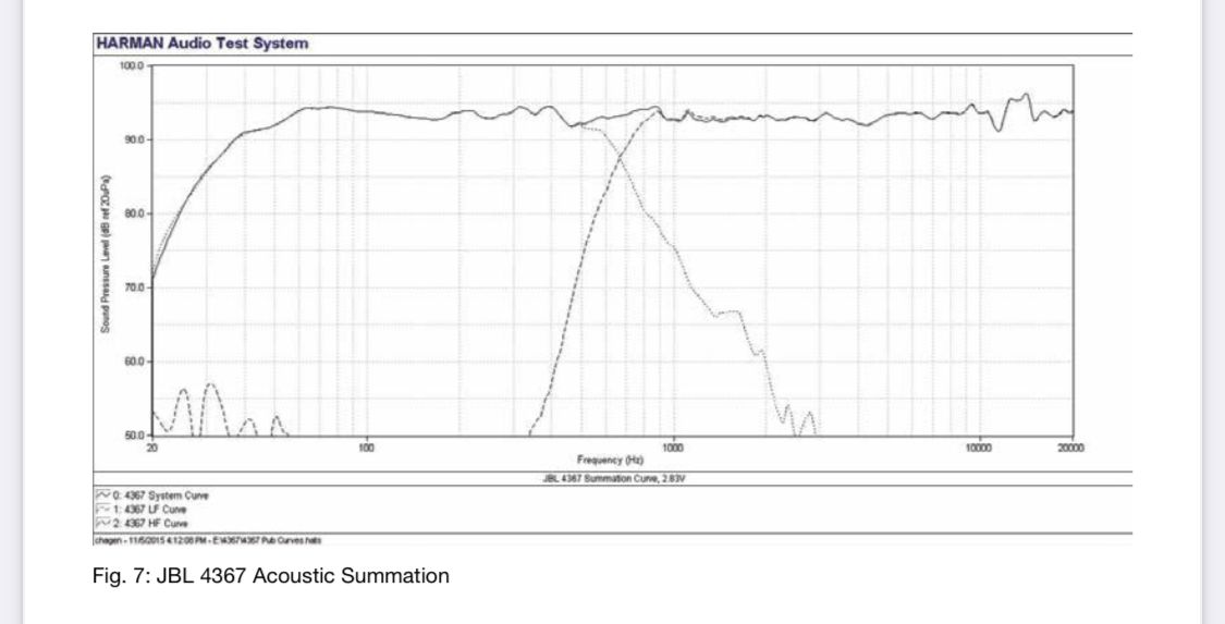
That good to know. I’m very curious as to the passive correction done in the 4367.
From about 8db down at 10k to essentially flat. I have no doubt Roy has this figured out but I would like to know how.
 Here is one form of passive tweeter EQ. The L pad is bypassed by a cap, and so can flatten out (to an extent) a tweeter's response. Don Keele clued me in to this many years ago.
-
001 thanks, do you have any pictures of these braces?
Yes, my friends living room is not optimal, so enclosing the backs is a must. Anyone have the dimensions required for these boards?
-
A friend just bought pair of 86 Klipschorns. He wants to enclose the backs. Does anyone have the dimensions of the boards required?
TIA
-
The first movie (with Frank Sinatra) didn't mention that, but the second movie certainly did!
-
William Manchester's "Goodbye Darkness" is the best war history book I've ever read. He weaves his experiences as a Marine in the Pacific theater with his then-current (late 1970s) quest to deal with PTSD.
-
1
-
-
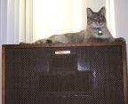
You know this is a modern reproduction, right?
-
16 hours ago, captainbeefheart said:
There are many forum members swearing by taking the two 1N3996 Zener diodes out of the circuit, just unbolt one of them from the bracket and let float to remove from circuit.
I was intrigued so I felt like taking some distortion measurements to see what is going on. In theory these diodes should not be doing anything unless you reach a peak voltage of 5.737v to where they would start to conduct and clamp the signal there, nothing higher can pass. In terms of RMS power it works out to a maximum of 2 watts going into the tweeters. Testing confirmed that the diodes indeed do clamp the signal exactly at 5.737v. BUT there was an unexpected outcome to taking distortion readings below this value.
Voltage readings are taken at the tweeter output across the diodes. They are peak voltages unless otherwise stated.
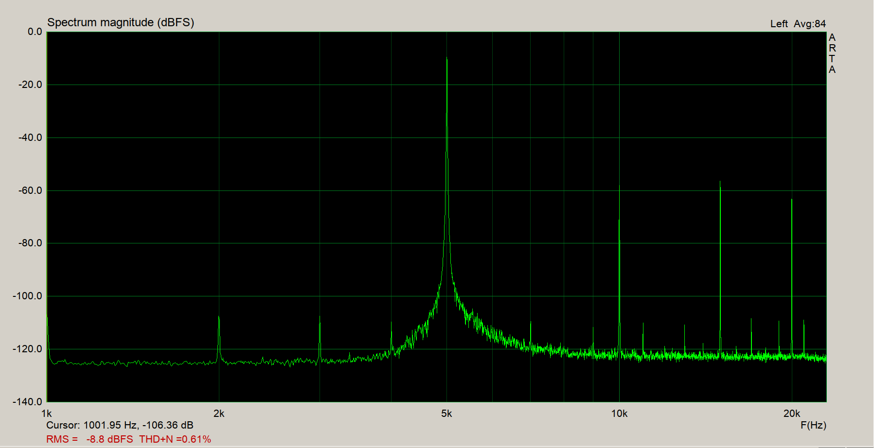
What I found was surprising. I didn't see any difference at 2.8v, both with and without diodes had identical distortion profiles. It's when you start to reach about 4v where things start go awry for the circuit with the diodes. As soon as you near 4v distortion starts to quickly build up with increase in amplitude. The pictures below are the difference between the network with and without the diodes at 5v. The zeners are clearly starting to do something at 4v, I am guessing it's the very beginning of their 'knee' where very little current is starting to pass and the diodes are somewhere in their dynamic impedance range, datasheet shows 300uA they are 100 ohms and linearly decreases impedance vs increase in current, at 600mA the diode is .2 ohms. Regardless of the mechanism they just don't clamp at 5.737v, clearly current is passing at lower peak voltages, I am seeing 4v is where the difference is happening at.
Now you might say to yourself that's still a lot of power. 4v peak is about 2.8v RMS, or 1 watt power. But you must remember dynamic range in music. If you are hovering around say 1 watt at the input of the crossover network, 20db dynamic headroom, a heavy crash cymbal may push a peak transient over the 4v for a very short period of time. 20db is 10x, so for 4v that's only around 400mV. I may be completely wrong but I can completely see even though we know the average power into the tweeter will be low, there must some signals passing over the 4v. Members have made it quite clear that taking these diodes out have impacted the sound positively, so they must be misbehaving during even modest play levels. My engineering mind was doubtful, the diodes are suppose to clamp at 2 watts and up, certainly must not be heard at in home listening levels, well it turns out that distortion is increasing rapidly at anything over just 1 watt or 4v peak into the tweeter. You may not be averaging 1 watt into the tweeter but you may hit it with dynamic music. If for whatever reason you are blasting away and you happen to reach the clamping voltage peak, distortion grossly increases, at the point of clipping you are already at 5% THD and it just gets worse from there.
Clearly in home listening is reaching the point where these diodes are creating distortion and effecting the sound quality. You can see the higher harmonics jump right up at 15kHz and 20kHz.
Ok, I have a question. Looking at the two traces, the harmonics between the fundamental of 5 KHz and the second harmonic of 10 KHz look to be less with the zeners acting. Also the odd-fractional harmonics between 10 and 15 KHz (third harmonic) look lesser. Clearly there is more distortion at 2nd, 3rd and 4th with zeners conducting. Also note that the "zener conducting" trace seems to have more low-level noise than the "non conducting trace." My question: Given the power distribution of most music, just how audible can the 3rd and 4th be where the zeners are conducting? I


 Here is one form of passive tweeter EQ. The L pad is bypassed by a cap, and so can flatten out (to an extent) a tweeter's response. Don Keele clued me in to this many years ago.

Show us your great photography thread!
in Lounge
Posted