Xover
-
Posts
45 -
Joined
-
Last visited
-
Days Won
1
Content Type
Forums
Events
Gallery
Everything posted by Xover
-
ZR-1 Sweet
-

-
31 hz is better yet. Not knowing your other variables my guestimate was 34hz. If when the time comes you need the signal source let me know and I'll try to get a useable reference from the function generator recorded to CD for you.
-
Bruce "If you could provide the exact effective internal volume (internal volume minus the space taken up by the drivers and ports) and the exact dimensions of the ports (diameter and length - flared or not flared), then it would be but a trivial task to run some numbers and come up with the dimensions for a slot port. I dunno why you'd wanna do that though...what project you working on?" In order to figure the port dimensions one needs: Volume of the box. Desired resonant frequency of the box. Desired Port width for example the tube diameter or the inside width of the cabinet for a slot port. If you want to determine the resonant frequency of an existing system go see my post in response to Doug's Idiot question #2. Usually the port needs some final tuning to get it spot on.
-
Hi Doug 29 hz Cool looks like you are shooting for a F3 in the mid 30s should sound great. Do you have what you need to tune the port? (Signal source @ that frequency range)
-
Pauln is on the right track here. Ground loops occur when there is more than one ground source. For instance you have the electrical ground and the cable TV attached somewhere that has the cable shield grounded ( probably to a plumbing pipe or a ground rod outside separate from the electrical ground). All electrical grounds in a residence should be common and all go to the grounding bar at the electrical building entrance breaker panel where it is tied to neutral. Look for some thing else that may be grounded touching the system someplace like phone wire, cable TV etc. Let's say the culpret was the cable TV the fix would be to peel back the shielding from the F connector just enough so it is not touching. The signal will not be affected because it still has shield ground from the far end.
-
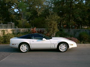
85 Coupe And every darn one has Bose sh...tuff All stock I conceed.
-
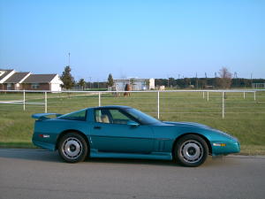
95 Roadster
-
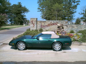
Here's my fleet: 88 35th Anniversary edition.
-
And you get those at Nations Rent huh? Daaaamn i had to buy mine.
-
Me again, that is exactly how I pictured your system from the first drawing. Do you know what your tuned frequency is going to be? It really doesn't make any difference in port placement I am just curious. Something else that I notice and you might already have this covered. The sides of the top portion are likely to vibrate and find some resonance unless you put some braces in. Since they are open this could done later.
-
Anyone use a TV Mount to hold a centre speaker?
Xover replied to dachuckster's topic in Home Theater
No TV mount but I possibly have a different solution. I have an excess pair of NIP black JBL MTC-51 speaker wall mounts. They don't have a weight holding specification and the heaviest thing JBL used them for was 24 lbs. IMO they are hefty and would hold much more. Look at link and see what you think. http://www.sweetwater.com/store/detail/MTC51/ If you think they'll work $20 and they are yours. -
That should work. Be sure to leave as much room on top of the ports to vent as possible. Also a angled plate above the ports to help direct the sound into the room might help. Some other thoughts on this. I have had good results venting at the bottom especially bottom back or bottom back corners to take advantage of boundary reinforcement of the port output. This assumes the cabinets will be resting on the floor near a back wall and are of a single chambered design the most common situation. Now back to how to tell if the ports have enough unencumbered space. Referring to my responding post on IQ #2: "This phenomenon can be observed by taking a bit of white label and sticking it on the woofer cone then cut a 1/2 in strip of index card and tape it so it extends about halfway into the port opening. Now sweep a low frequency and you see the woofer cone nearly stop when the card strip reaches maximum motion." Set up this condition at the port tuned frequency and observe the white dot on the woofer cone as you move the obstruction closer. You will see the cone start to unload IE cone motion increase when the obstruction is getting too close. BTW these are good questions and you haven't seen my art.
-
Just a thought. Why not cut the baffle board in half ( actually closer to the woofer leaving enough room for a horizonal brace where the two Baffle parts meet. This will allow you to remove the bottom portion to tune the ports. It would also allow you to make extra bottom pieces to try different port placement. It is my experience the port placement is not critical so long as there are no obstructions front or back to cause turbulence and you tune the ports in the box real time ( theoretically one could possibly stick the ports in backwards so they extend out in the room for convenience while tuning). I found that if you place the ports in the bottom corner of the box it works fine but the tuning length is a bit shorter than elsewhere on the baffle.
-
Check this out Eclipse Lives! http://www.madisound.com/cgi-bin/index.cgi?keywords=eclipse&cart_id=9664679.28759&imageField.x=26&imageField.y=13 BTW whatever happened to Speaker Lab I'm guessing they went **** up but anyone know the story?
-
Hi Again Doug Good question and not real easily answered but I can tell you how to find out. Since I responded to IQ #2 I suspect that you have a deeper concern or project can you tell us more? Maybe that will help me answer this one.
-
Hi Saint The answer to your question is yes you can. There is a caveat though you need to know about. The 5.1 sub is tuned to the 6th order, you don't have to know exactly what that is all about but how it affects what you are doing. In the 6th order design the port is tuned 1/2 octave lower than normal then the signal is electronically boosted to achieve flat response for the bottom octave let's say 25 to 50 Hz and typically there is a sharp low cut filter below 25 Hz. So what to do, what to do, you have several options. 1) Slap the plexi on and run it. The bottom octave bass will be weak. 2) Same only tune the port 1/2 octave higher. Your bass cutoff will be 1/2 octave higher but still good. 3) Same as #1 but set your equalizer to boost 6Db @ 25-30 HZ then cut off below 20Hz. Good choice sound will be like you expect. Go for it and enjoy!
-
Idiot question #2: Ports general question
Xover replied to filmboydoug's topic in Technical/Restorations
Doug Yes the port changes the way the woofer "sees" the cabinet. First let's talk about a sealed cabinet, in a properly designed sealed system the volume of trapped air inside the cabinet acts to limit or dampen the cone excursion of the woofer. This is the compression of the air on the in-stroke of the cone and the rarefaction of the air when the cone moves out. Now on a vented design we do not have this compression damping effect. On a ported system the cabinet becomes a Helmholtz resonator. When you blow across the top of a gallon glass jug and the air in the jug hits a resonance and gives off a low frequency sound you are creating a Helmholtz resonator. For the volume of a cavity and the length and diameter of the port the oscillation will occur at a single frequency. In a properly designed bass reflex (ported) system the tuned frequency will be just below the resonant frequency of the woofer. At driver resonance the magnetic motor system of the driver impedance swings high and loses some control over the woofer cone. Without some outside force to help control that cone motion damage could occur. The box resonance of the speaker will be 180 degrees out of phase with the woofer. These out of phase pressure waves caused by the port will effectively dampen the woofer cone excursions at resonance. Thus the bottom octave sound will come almost entirely from the port. This phenomenon can be observed by taking a bit of white label and sticking it on the woofer cone then cut a 1/2 in strip of index card and tape it so it extends about halfway into the port opening. Now sweep a low frequency and you see the woofer cone nearly stop when the card strip reaches maximum motion. -
Thanks Dean Yes I am new to the forum and no I am not familiar with autotransformers in the networks. I've been at this 30 years but it's new to me. I have always tried to put as few components in the signal path as possible but then I,ve never tried to keep tube amps or any amp with a transformer output happy. Zobels yes if I have to but no transformers. I see you are from Kettering that strikes a chord talking about autotransformers.
-
Guiness For starters I am not familiar with the Cornwalls other than what I see in pictures but I am somewhat versed in networks. What you have is a good start but probably would be disappointing in reality. Making assumptions about speaker impedance ends up like making assumptions about buying clothes for your wife. It is too easy to find the real life impedance and be sure (or just send her off with a credit card). It does take a little effort and equipment but the end result makes it all worthwhile. Simply go get a 1K ohm resistor and put it in series with the speaker driver. You can use a 1/2 W resistor since volumes can be kept low. You will need a DMM but they are available for little these days and I found one that includes a frequency count function. You will also need a function generator for a signal source, alternately one could use one of those test cds that have known frequency bands actually you could record someone elses function generator or cd on tape and use that. Anyway the idea is to sweep the crossover frequency to that particular driver while measuring the voltage drop across the resistor and then the driver. Since you know the exact impedance of the resistor (measure it with the DMM don't trust the 1K) and you know the voltage drop that impedance corresponds to and you know the voltage drop across the driver you can use proportions to determine the exact impedance of the driver at the crossover frequency. You will find that the impedance across the drivers varies significantly with frequency so be sure that you measure at the intended crossover frequencies. Then plug the values into your formulas for determining capacitor and coil values. You will probably find that the calculated component values do not match common capacitor or coil values. Capacitors are easy in that capacitance in parallel is additive. Chokes on the other hand can be hand wound to exact values I have done this before and the sound difference is remarkable.