henry4841
-
Posts
2370 -
Joined
-
Last visited
Content Type
Forums
Events
Gallery
Everything posted by henry4841
-
LaScala's It is easy to check your speakers yourself if you have a AC voltmeter and use ohms law to find watts. Most are astonished just how small power is needed with Klipsch speakers. The 1/3 watt figure is average with peaks being more. At the level I listen at the signal never tops 1 watt. This is a 2 watt rated amplifier at 10% distortion. It will do more with more distortion but the thing is it will be on peaks and not noticeable. A tube amp can clip and you will never know it. Two watts of tube amplification is all we need with our speakers. Nelson Pass has oscilloscope hooked up to his system set for a 1 watt window and the signal stays inside the 1 watt range when it is playing loud with less efficient speakers than ours.
-
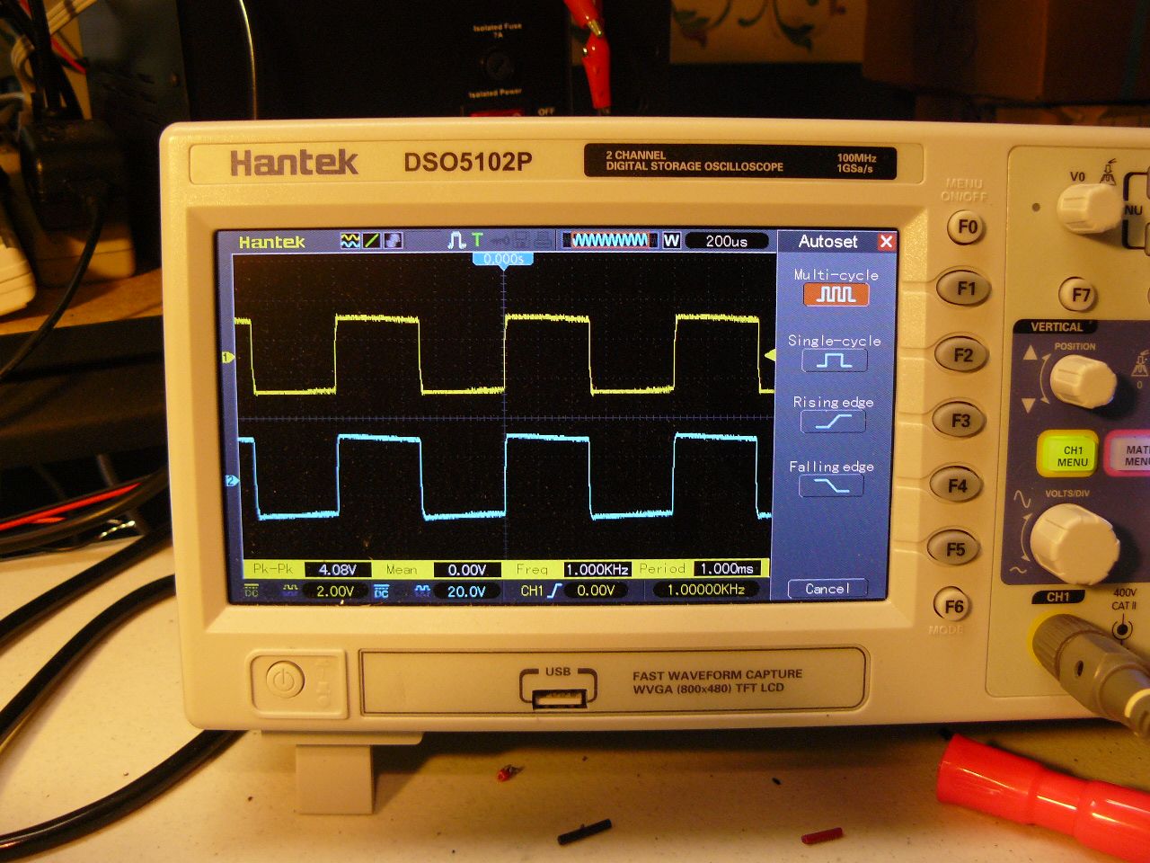
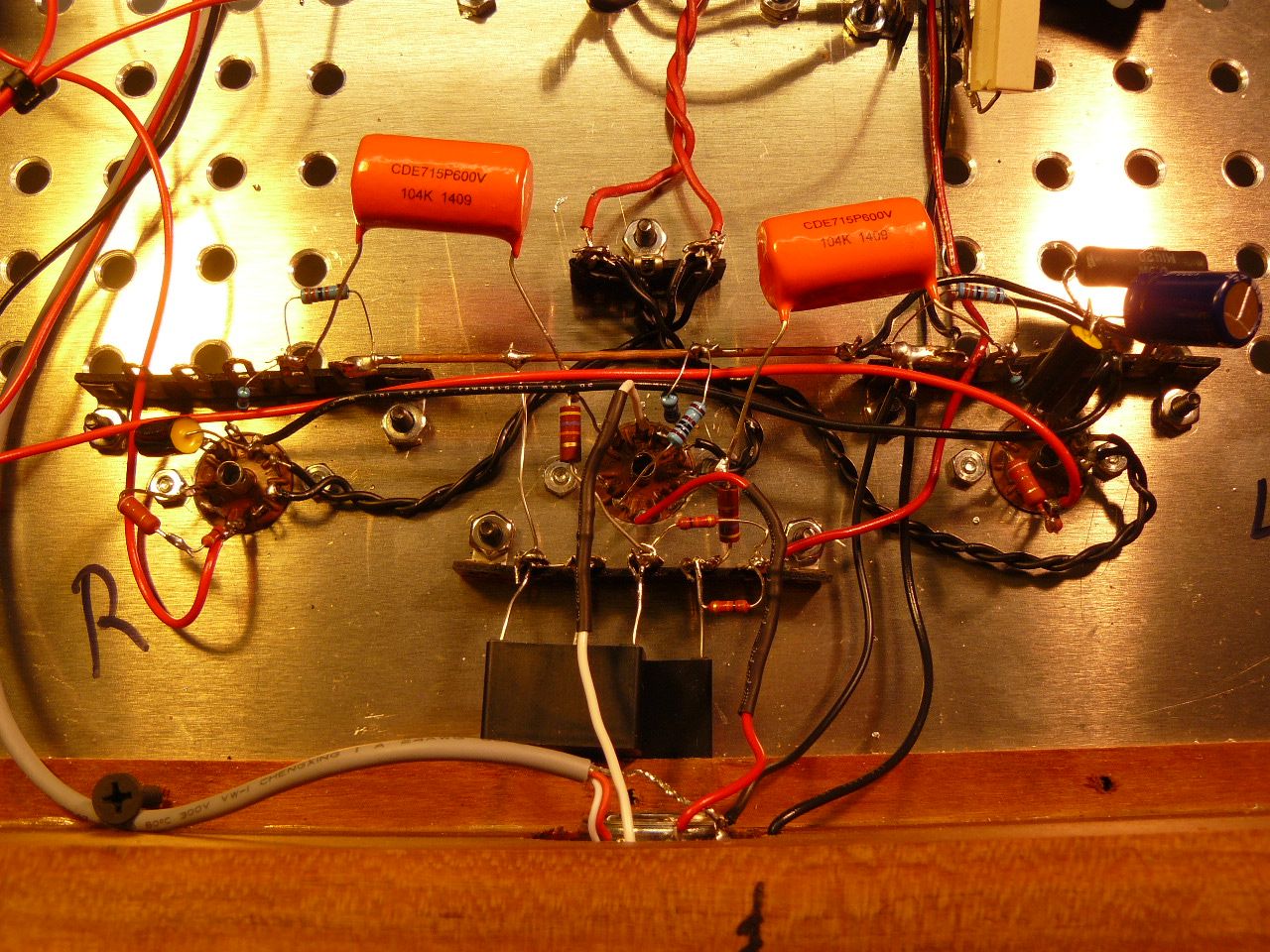
Below is the square wave signal at 1khz 1/3 watt, respectable. Some comments on this design and build. Anyone is welcome to join in. Going through the parts I removed I found the two .1uf film caps that I assume were attached to the screen grids to K of the first build called by Steve the hazen mod. The hazen mod was not shown on the first schematic I built from but evidently I knew about the hazen mod and installed the caps. Taking measurements this morning I found I am running the 6P15P tubes at 10.95 watts. A touch more than I like being this is a 12 watt tube which possible could shorten the life of the tube. But since this amp is for my personal use and knowing with so many amps I will never put that many hours on it I think I will let it be. It possible could sound and work better working a little harder. I do have a 200ohm 5 watt resistor left over from the first build I assume was installed in the power supply section in series with the 1Kohm 6 watt resistor lower the voltage some which in turn lowers the dissipation of the tube probably more close to the 10 watt range I was shooting for. For now I am just going to let it run as is. Running a 12watt tube at 11watts is not critical and I see no red spots on the plates. One thing that caught my attention is the overkill on some of the resistors wattage rating. I measure only .66watts dissipation on the cathode resistor of the 6P15P tubes. Steve's schematic shows a 150ohm 5 watt resistor. IMHO a 3 watt resistor would be plenty good enough. I must say now so not as to cause confusion this is not the Decware Zen amplifier currently being sold by Decware nor one of the old ones either. Different components are being used from different manufacturers along with me not following the schematic part for part either. I just call it a SET EL-84, 6BQ5, 6P15P amplifier. I've used the 6P15P tube in some of my other builds such as my PP class A amplifier by another designer. Rock solid tube from when Russia was making some fine tubes. I was short with only one part, the 1K 2watt suppressor grid resistor. I had a 800ohm 2 watt one and a 1watt 200ohm one in my stock so I tied them in series for the 1Kohm. I was concerned if the 1 watt 200ohm was being pushed hard so I took some measurements and found only .32 watts in the suppressor grid circuit. Another case where a 1watt 1K resistor would work just fine. A few of our electronic geek members have chose to move on since the big purge which is a shame. Perhaps we can generate some more members on this forum to try diy. This is the reason for my posting builds on this forum. Join in guys. Your thoughts, opinions welcome.

-
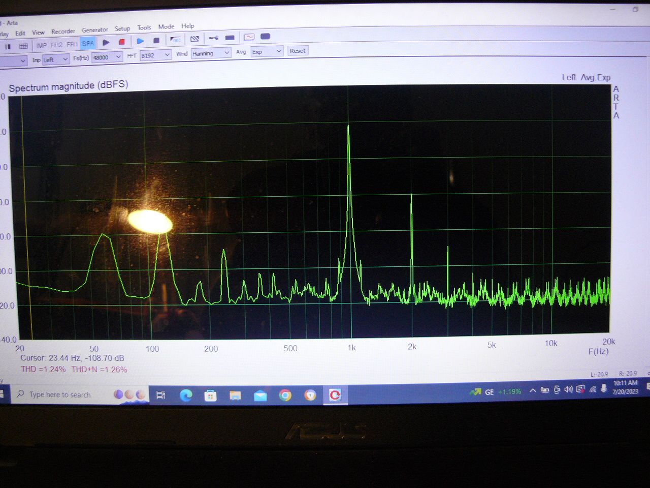
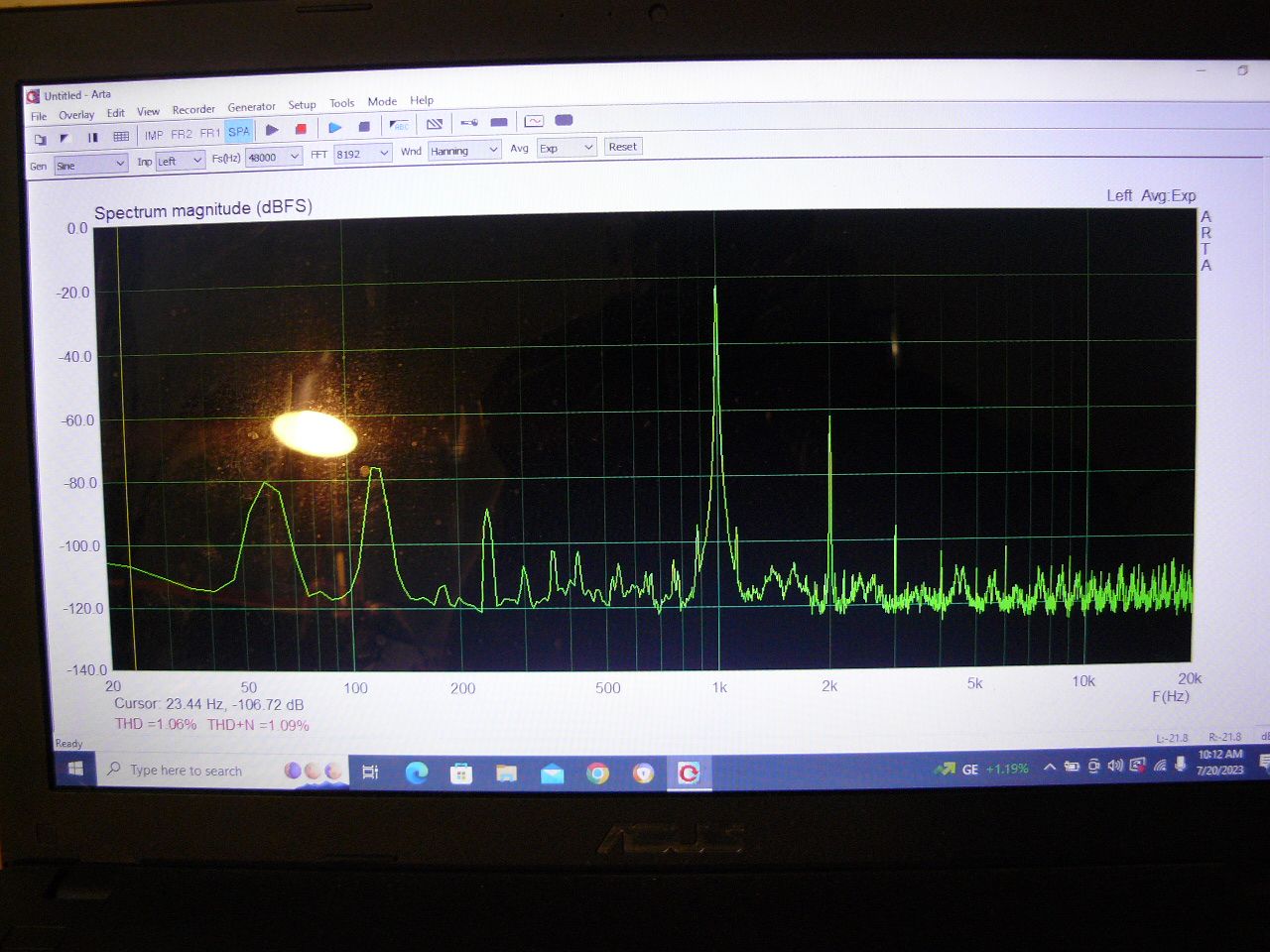
This was a rebuild of an old amp I built years ago and I tried not to replace or change anything from the original build other than appearance. Below is some distortion pic's and numbers to look at. I tested this little 2 watt amp at 1/3 watt. It is only fair not to test a 1 watt to show but I did take a look myself yesterday and even at one watt it was respectable. Last night while listening to it I measure the average wattage number I was using with the music at my normal level. Your wife would call it loud, and 1/3watt was my average level so that is all the power my Klipsch speakers need to really sing loud. One thing that is very important to know is when I originally built this amp I was not expecting a lot from 2 watts so I just purchased some really cheap output transformers. Good quality mind you but lower on Edcor offerings. This OPT's sell for just $32 right now and work great. At least I think so. At 1 watt output I did noticed some distortion of the signal at the extreme high and low frequencies but never heard any of it while listening last night. Reason being my average usage is just 1/3watt. Testing at 1/3watt this morning pushed the performance with a clean signal to 40hz and 18khz. These little OPT's exceeded my expectations. They sound really good for not a lot of money. https://edcorusa.com/collections/tube-amplifier-single-ended-output-transformer/products/xse10-10k-10w-10k-ohms-single-ended-tube-output-transformer Just for the record I have two sets of new Hammond 125dse OPT's I could have used but they are just not needed for this build. I think one of the Hammond 125CSE's or the Edcor GXSE10-8K- 10 watt ones will work perfectly but for those wanting to build on a budget I find nothing wrong with these $32 OPT's. In the screen shots the distortion numbers are predominantly 2nd harmonic, the kind many want in their music. Touch of 3rd as well. What you expect to see with a SET with no feedback. I will post more test results later today if I have time or first thing in the morning. I do want to discuss this build more and what I think of it.
-
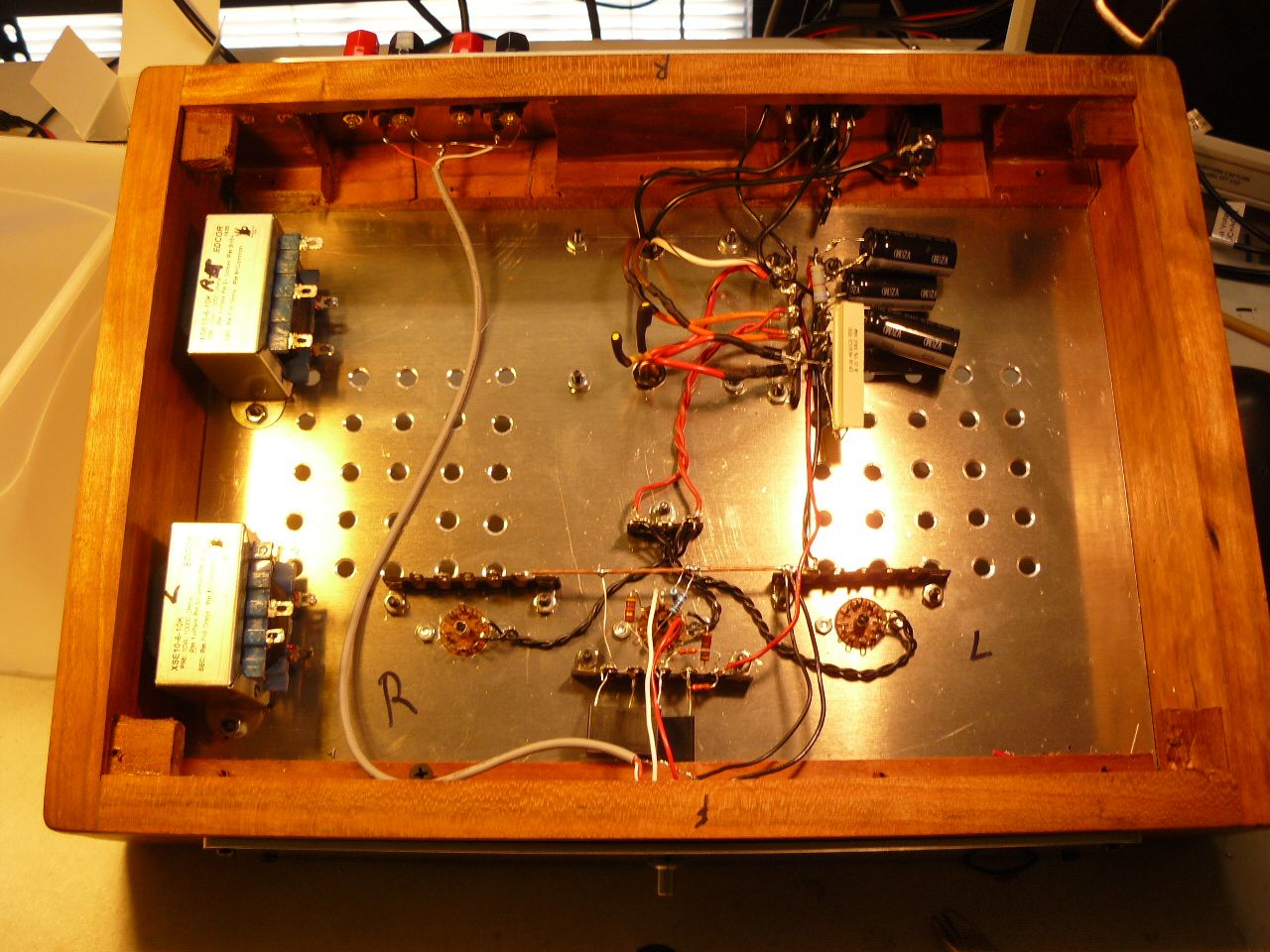
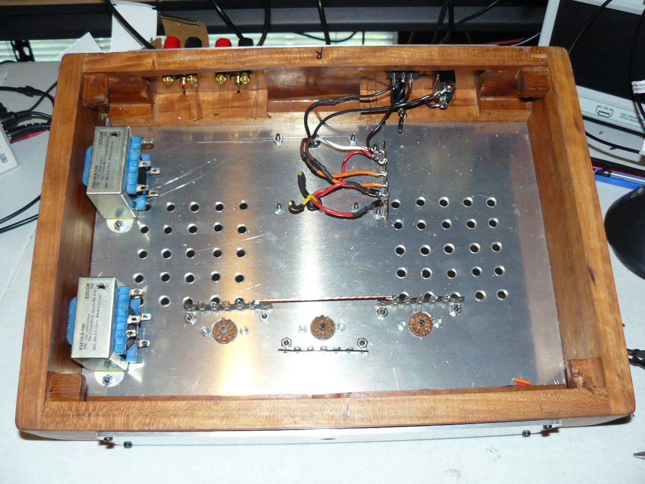
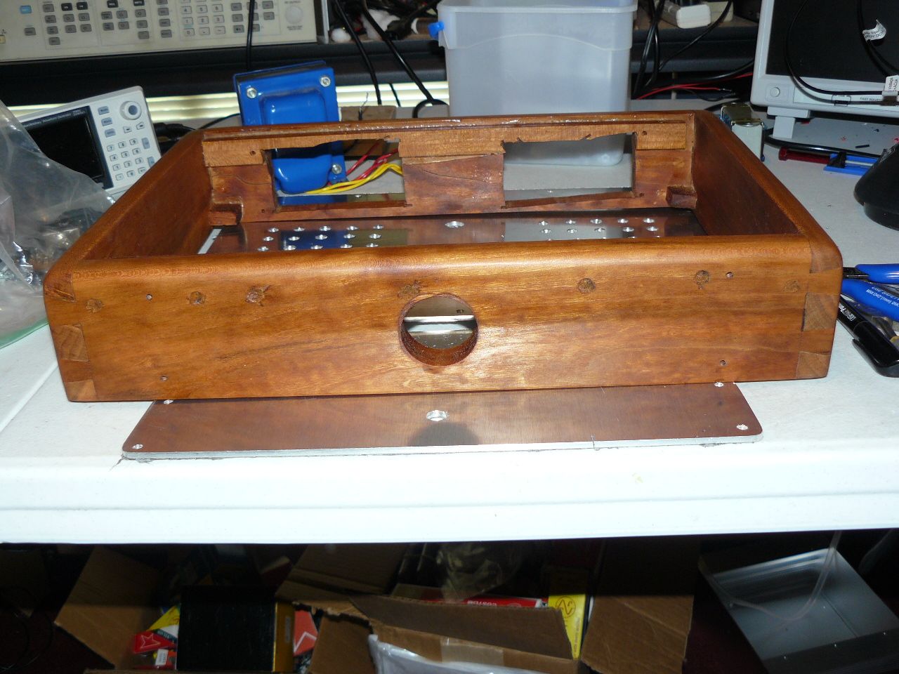
Did some testing this morning on this new build along with taking some pictures of work underneath the chassis.
-
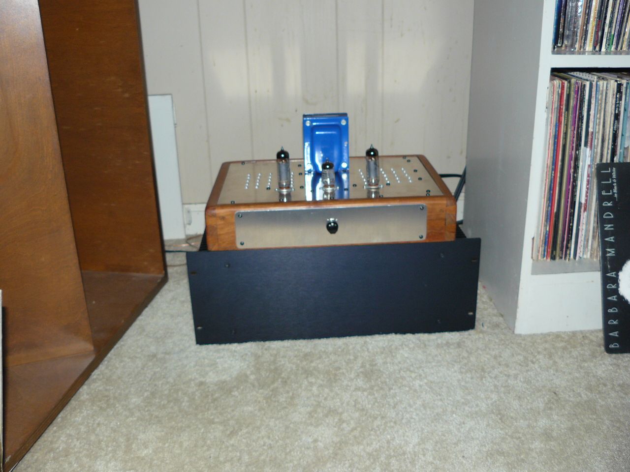
It's alive. More pictures and discussion of amp build later.
-
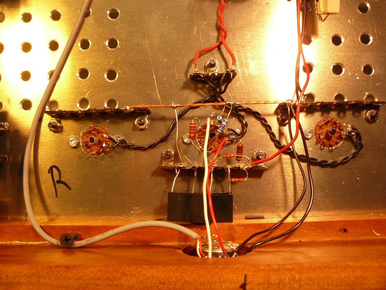
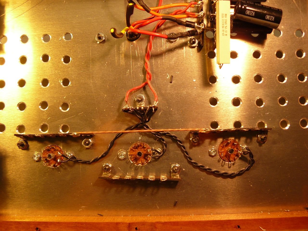
I finished the ground connections this morning to start with. Then I started wiring up the two sections of the input tube. The 6P1 tube has two triodes in one envelope enabling the use of one tube for both channels. Steve elected to use two resistors in parallel on the cathode of each of the 6P1 triodes. What the old schematic I used years ago does not show is a switch where you can use both resistors in parallel for a resistance of 964ohms on each cathode or switch to where you are only using the 1.5K ohm on the cathodes changing the sound to some degree. Could be something to play with if one chooses but I honestly do not like playing with an amplifier I am listening with so I elected to just use one 1K ohm resistor for each cathode. I listened to this amp this way for many years and enjoyed the sound so why change. Roger Modjeski was the first person who pointed it out to me how one could change the sound of your amp by substituting a variable resistor on the cathode of the input tubes tailoring the sound to ones taste. You may consider this if building this design yourself. So far things are going well and I am almost finished with this build. I estimate 4 or 5 more hours and it should be finished. This is with me being slow and old. A young talented person could finish it in much less time I am sure.
-
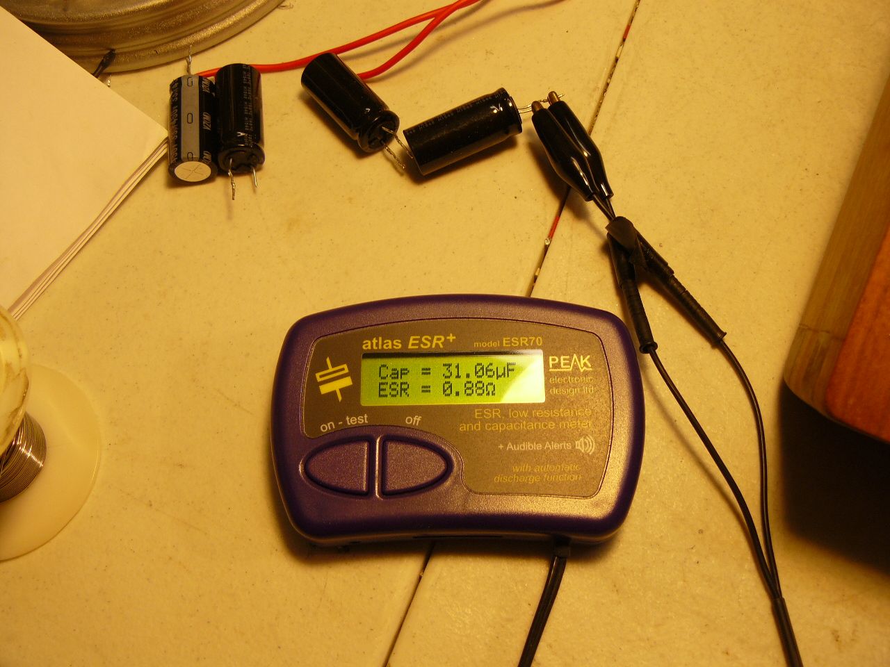
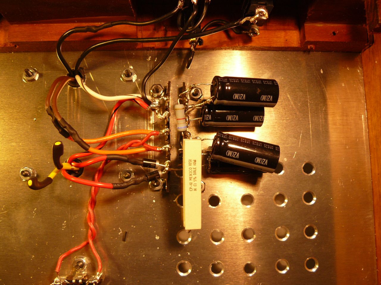
Got what I was planning on finishing this morning done. The power supply section and the tube heaters are wired. First I tested my capacitors with my Peak meter just to be sure nothing was damaged during removal. All test within tolerance. These caps are close to 8 or 10 years old but with less than 50 hours on them. Probably more like 20 hours being with so many amps none of my tube amps have their tubes broke in yet with me constantly taking one out and putting another in. Most consider 100 hours necessary before tubes sound their best. The power supply section went well with no hiccups. Steve's chose of cap values is somewhat unusual because the second cap is more like 100uf to 150uf on most of the modern designs I have built. The first cap is a normal value when used in a tube rectifier circuit, 33uf. My build is with SS rectification so I could probably get by with more uf in that first cap if I chose to. The final two caps in the PS are in series with a working value of 10uf when in series. Steve is using 2 caps in series of 250V's increasing the amount of voltage the caps can take to 500V's. Overkill in that position where the working voltage is going to be much less. If I were designing this amp I would use one 150uf 350V cap in that spot. When I originally built the amp I used two 33uf 450 caps in series, probably back then not knowing exactly why the two resistors were in series. I was just following the directions, schematic, building without understanding circuits as well as I do now. Being my caps are 33uf 450V's ones I hooked the two I had in parallel creating 66uf of capacitance with a 450V rating. Not going to make a difference audio wise but may show better numbers during testing using more capacitance. The heater circuits are pretty much self explanatory. There a number of ways to wire the heaters and this is the way I settled on some years back. Later this week, hopefully tomorrow morning, I will start on the first audible circuit, the 6P1 tube. I may make some changes in the circuits when I start wiring them. Using old parts with leads cut short I had to add wire to the leads to make the connections I wanted to use. Not as neat and clean looking as when using new parts but this is after all a rebuild using the old parts and the parts I have on hand. I do not believe I am going to have to make an order with Mouser to complete this amp.
-
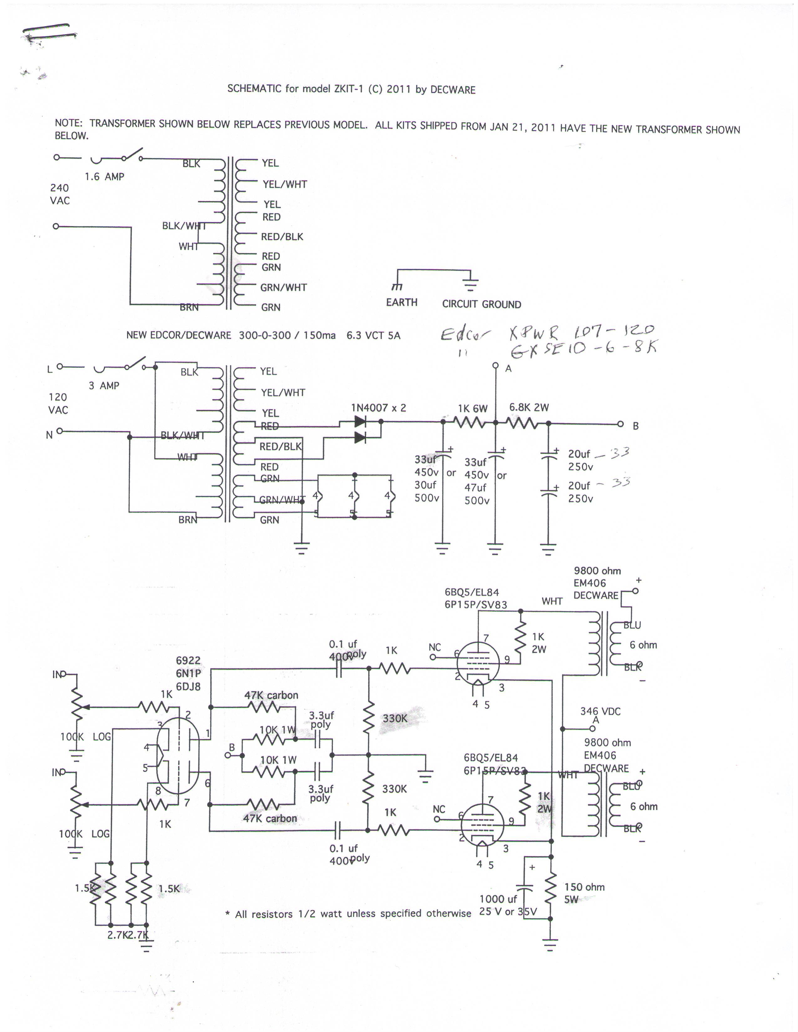
The above schematic is a later one from the one I am I will use. I just got my scanner working again so here is the main schematic I am working from. Being there are some changes in the latest published schematics by Steve that do not show the values of part I will deviate from this schematic and implement some of those updates. Figuring out the value is not that hard if I choose to do so. I am using SS rectification instead of tube for this build. I just do not worry too much of the type of rectification as others. I am sure though that rectifier tubes do color the sound but having built both types I really do not hear that much difference. I have about as many tube rectifier amps as I do SS rectified ones to say this. This is an older published schematic once circulating on the web.
-
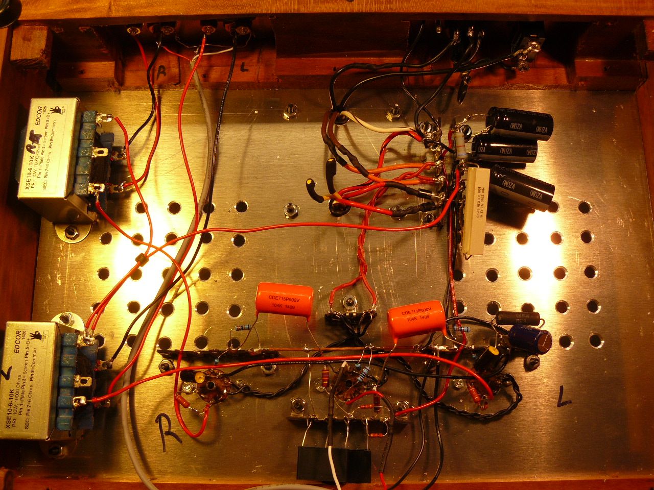
For those interested, the orange wires are the heater ones, red ones B+. The red and black stripe along with the white and brown stripe are center taps that are going to a ground point I made right close to the power inlet. The B+ red wires have diodes attached to them and then the diodes are tied together attached to one point on the standoff. The diodes have turned the AC from the transformer to DC but not pure DC yet. There is a good bit of AC ripple still with the DC needing smoothing in the power supply section before it can be used by the amp. Main AC from the IEC connector goes first to the fuse, then switch and finally to the transformer. The other lead from the transformer goes to the common connection on the IEC connector. On the schematic one may notice on the heater section Steve used a transformer without a center tap making a virtual ground with two 100 ohm resistors. My PS transformer has a center tap so I do not have to make a virtual ground for the heater section on my build. It is easier to understand what is going on if one just takes it one section at a time using the schematic. I stopped on the schematic Saturday at the 4007 diodes. Actually I used a larger diode 1N5408 I believe is the number with a 1kV 3amp rating vs the 4007 1K 1 amp rating. I have plenty of them along with the 1N4007 diodes in stock using the larger ones because of their stronger leads. The 1N4007 is plenty good enough for this little amplifier.
-
Older vs newer Klipsch, new member.
henry4841 replied to Mark Swearengin's topic in 2-Channel Home Audio
I believe I know the answer to that question. At some year Klipsch went to using 1" MDF over 3/4" plywood in their speakers. Denser, flatter and smoother and most importantly cheaper it was a win though I have not found anything wrong with plywood myself. Also MDF is heavy as hell. -
Older vs newer Klipsch, new member.
henry4841 replied to Mark Swearengin's topic in 2-Channel Home Audio
I should add, newer ones excellent too but with a different sound. I like the sound my old LaScala. It is the sound PWK designed and built. Excellent sounding then and excellent sounding now. What you are hearing with a newer Heritage speaker is the sound the engineer at the time thought sound better than the one before it. He then convinced management who put the product in production. I do not believe any of those engineers would say their predecessor designed a bad sounding speaker. Much can be said about amplifiers as well. All the better amplifiers sound really good but with a different sound. When talking over 1K doubtful there is a bad sounding amplifier. -
Older vs newer Klipsch, new member.
henry4841 replied to Mark Swearengin's topic in 2-Channel Home Audio
Older ones sound excellent. Newer ones sound different. -
A little more work done this morning. I should be ready to build a circuit come Monday. It will be the power supply circuit first and then if time permits wiring up the tube filaments. That is my plan at least.
-
https://www.diyaudio.com/community/threads/building-the-tu-8900.376170/
- 1 reply
-
- 1
-

-
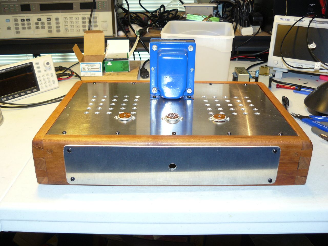
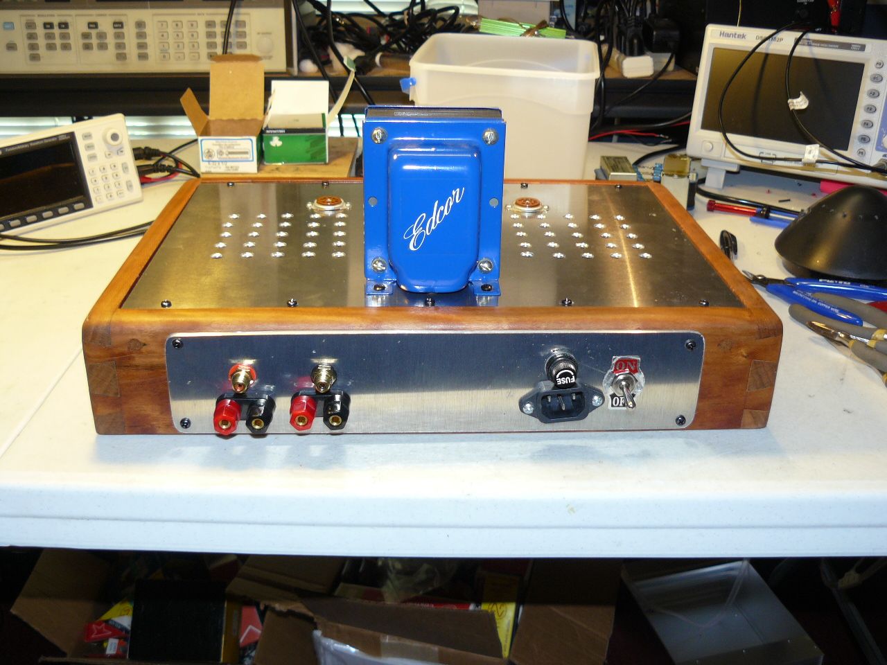
Coming together. No surprises so far which is a good thing. The IEC connector is a little crooked, so what. It is more than likely going to stay with me and I do not have a habit of looking at the back of an amplifier that often. The front pot has to be wired before it is installed. I think it would look better if I took those ugly blue covers off the transformer and painted them back but I am going to go with what I now have. If it were for sale it would be done.
-
After some thought, the number of .040v's rms needs converting to the more common THD+N just as you said. Companies do this to confuse or for more talented electronic guys than myself. Just how do you get rms into the equation? Above my head. Best way to be sure is try and find a reviewer that has put that amp into a lab test to get the THD+N number.
-
I do not feel it necessary being modest consumer amplifiers should be quite on our speakers. If you hear hum or noise chances are something is wrong with the device. I am not familiar with comparing uVrms with what I mentioned. I am sure there is info on the net that would do so for those interested.
-
I thought Klipsch speakers were sprayed with lacquer and not an oil finish. I quit using those can fillers years ago preferring to make my own filler with the same wood sawdust of the product and wood glue. Easy to get right sawdust from a piece of scrap, in this case oak wood, with an electric sander that catches the dust. Mix with glue and apply. No better match that I know of. Not perfect, one can still notice if picky enough but in most cases not noticeable from a reasonable distance.
-
Most of the distortion analyzers give THD and THD+noise figures. I have found a noise figure 50db down from primary signal to be quite on my LaScala's and plenty good enough. Noise, hum mostly, not heard.
-
The thing is in the above example of electrons flowing through a single resistor as a byproduct of electrons going through a simple resistor there will be trace amounts of inductance and capacitance as well. This is considered distortion because the only thing you want a resistor to do is slow down the flow of electrons. Not enough byproducts to be a concern in a simple resistor but it is there. Where such becomes important is when dealing with active components mostly, tubes or transistors. Both can have significant amounts of capacitance between the leads which can be detrimental. Amounts are stated in the data sheets of tubes and transistors. When you start with parts with distortion you are just going to add more distortion with all the other components. The trick is to keep the numbers down where it does not effect the sound much if any. I personally prefer an amplifier with some 2nd harmonics and a touch of 3rd as the famous designer Jean Hirago stated as best decades ago. Nelson Pass agrees so I am in good company.
-
Sorry and not go argue but if one knows anything about electronics you would understand zero distortion is not possible. There is always going to be measurable distortion in any electronic product. Electrons going to a straight piece of wire will have distortion along with the signal. I have never heard of any test equipment, used to accurately determine distortion ,with zero distortion. Just not possible in reality. If someone can find a distortion analyzer with zero distortion I will be open to see the ad or product. Does not exist. Lab equipment gets the numbers down really low but some is always going to be there. I am talking 5 and 6 figure tests equipment. They will proudly display their distortion numbers which can be extremely low only measurable with better test equipment.
-
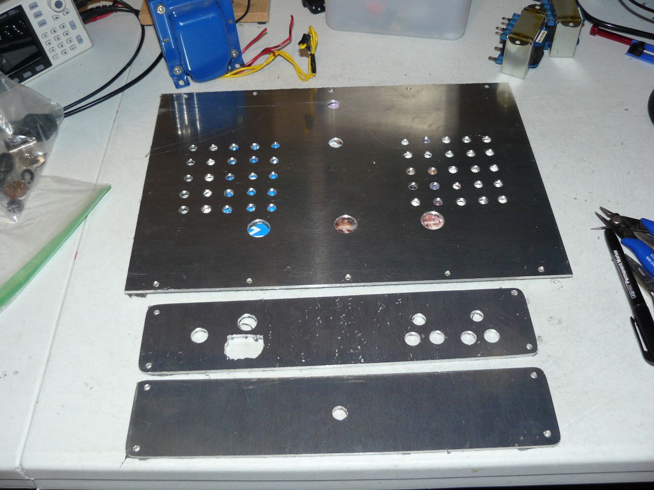
Got in a few hours of shop time this morning after cutting big limb that fell in my GF's back yard this morning. I believe I am about ready now to start some assemble and using my soldering iron. A good friend of mine does not care too much for all the holes I drill in my top plate. Personally I like the look and they do serve a service of letting the heat underneath the amp escape which means long life for the amp. I now build amplifiers that look like they are built like a tank, meant to last decades and sound good with good parts. There is always talk of capacitors needing replacing in crossovers on this forum. Nelson Pass stated on another forum about seeing his 40 year old amplifiers and the caps still test good. Using capacitors rated above what is needed, where they are not working close to their limit, and keeping everything cool is how to achieve long life in a product. By the way the pictures show the back side of the plates which have some scratches that are not going to be seen. I still have the protective covers on the plates but I thought one could get a better idea on how the chassis is going to look showing the back shiny aluminum.
-
And here is the problem Randy I believe is your name, distortion is stated at full power and not at .5watts with no mention of distortion at .5 watts. This is the way class A/B PP amplifiers with lots of power have been rated for as long as I can remember so your hypothesis of zero distortion is not accurate. That and zero distortion is not reality with any electronic product. There is always going to be some distortion. Another factor to consider is PP A/B distortion is odd distortion which is very unpleasant whereas even distortion is pleasurable for many. What is meant by even and odd for example is let's say the signal is 1Khz. Even distortion is going to be 2Khz 2nd harmonic and 4khz the 3rd harmonic distortion. Odd is just the opposite. All this is just technical stuff because in reality all the better SS PP A/B are going to sound just fine. The thing is though a SET tube or class A amp from Firstwatt is going to sound better. That is if one has the hearing to compare. Let's face it guys, many are just fine listening to Bose.
-
One would like to think the makers of those high power amps would have corrected this problem at low watt usage but I have my doubts. Why, because those that buy those mega watt amps will probably be using them on inefficient speakers which do not wake up till they see a lot of watts. In other words the market for high power amps is low efficient speakers. I would like to think that the high end audiophile amps will have low numbers at low watts but it could very well be not the case. Our speakers are perfect for low wattage tube amps. Most audiophiles with other speakers will not be able to use or hear the wonderful sound SET amplifiers make with our speakers. On my LaScala's, in SS, I look for a well respected 25 watt or less amplifier. Naturally the offerings from Firstwatt are perfect with our speakers but do not expect .0001 numbers from Firstwatt. Nelson designs Firstwatt, most of the time, for a little 2nd harmonic and a touch of third which is considered by many to be the ideal amplifier and sounds the best.