captainbeefheart
-
Posts
1422 -
Joined
-
Last visited
Content Type
Forums
Events
Gallery
Everything posted by captainbeefheart
-
Little Sweetie Forum amplifier project
captainbeefheart replied to henry4841's topic in Talkin' Tubes
For anyone reading and interested in Schade feedback, here is a great resource from O.H. Schade himself on beam power tubes. Inverse voltage feedback is what he calls it and gets going on page 43 in the pdf or 176 in the book. https://worldradiohistory.com/BOOKSHELF-ARH/RCA-Books/RCA-Beam-Power-Tubes-O.H.-Schade-1938-48-pages.pdf -
Little Sweetie Forum amplifier project
captainbeefheart replied to henry4841's topic in Talkin' Tubes
I too don't prefer ultra linear, especially in single ended amps. Some push pull amps in UL can sound good, but still not my preferred method. When talking about pentode vs triode curves that's with the device on a curve tracer alone with no help from that dirty little word; feedback. Feedback is what gives a triode it's curves, although it's not an external connection, it's internal, but nonetheless still feedback. From the RH84 amp which is a real popular amplifier is an EL84 in pentode operation but it has plate to grid feedback also sometimes called "Schade" feedback. You get the power of Pentode but the feedback transforms the curves into more triode looking curves and greatly reduces distortion. I like both methods of feedback, Schade and typical output to input. I have kinda settled on building with global feedback, output to input because it incorporates the entire circuit into the loop and gives better overall circuit results. If you do try a more powerful Sweetie design I'd start with something like the RH84 "Schade" feedback scheme because it already has a pentode driver which works very well with that type of feedback due to the high plate impedance of the 6SJ7. You may need to play with the plate to grid resistor value, start at 1Meg and reduce it down until you find the sweet spot, you'll most likely end up with a final value between 220k-560k. -
Why No Bandpass Filtering on Woofers?
captainbeefheart replied to Peter P.'s topic in Technical/Restorations
Here is the frequency response of an Eminence Kappa 15" speaker. Notice it's natural roll-off characteristics at low frequencies. The most problematic excursion issues I have seen were from record players creating low frequency oscillation. This is where a high quality preamplifier and it's internal filtering will take care of some of those issues even including a "rumble filter" which was on almost every preamp back in the days of when we only had records to listen to. Basically just a low pass filter is all that is needed and the speaker itself rolls of enough as frequency is reduced. Which is why I and many also use sub-woofers with our setups because a woofer can't really produce excellent low frequency results without tuning the box and even then you should really only go down as far as the resonance which looks to be around 48Hz with the Kappa. The resonance may move a tad but it won't move down to 20Hz. I do admit I'm more into electronics and I don't build or design speakers. Someone that does may jump in and explain it better. -
tree-fiddy
-
Crossover Capacitors and Crossovers In General
captainbeefheart replied to Curious_George's topic in Technical/Restorations
For what we are doing, capacitors are relatively the same construction, same loss angle, close enough in value of capacitance to where viewing it like I am is fine. If one was say to use a 10,000uF electrolytic and paralleled it with a 1000pF ceramic then due to the "resistive" elements of the eqivalent circuit (ESR) not being technically in parallel use the impedance formula. https://www.diyaudio.com/community/threads/esr-with-paralleld-capacitors.347197/
-
Deano is an approved Klipsch network builder
captainbeefheart replied to Chief bonehead's topic in Technical/Restorations
That makes sense, play it by ear. I love what Klipsch does, always have. I own multiple pairs of your speakers. Thank you for all your hard work and what you do we all enjoy it. I always thought education is great, I love learning and I like when others get excited to learn. I'll do my absolute best to help anyone. -
Deano is an approved Klipsch network builder
captainbeefheart replied to Chief bonehead's topic in Technical/Restorations
Now that sounds like a winning Combo!! I think this move from Klipsch was extremely smart. -
Deano is an approved Klipsch network builder
captainbeefheart replied to Chief bonehead's topic in Technical/Restorations
I think I could have worded my thoughts better. All I'm saying is you or anyone else from the company doesn't necessarily need to defend it personally. I'm just saying, for example, when the guy came in asking for advice on someone upgrading their Cornwall networks. I think everyone here knows what thread I'm talking about. Someone such as myself will defend Klipsch with technical facts to put some doubt into the "upgrades". Or is it if someone comes in and makes a similar thread will it just get deleted? -
Deano is an approved Klipsch network builder
captainbeefheart replied to Chief bonehead's topic in Technical/Restorations
Congratulations Dean, I'm sure it must feel great to be contracted to work with one of the all time great American Speaker manufacturers. Few things. I personally never knew there was a service/repair arm of Klipsch for their heritage line until JEM. I'm sure since this move happened the more thought was put into allowing competitors to peddle their wares here. If the service arm is part of the bottom line profit for the company then I can understand. One thing I am still confused about is us customers discussing both Klipsch service and competition, should be fair to discuss right? I mean Klipsch shouldn't have any worries about competition and I personally feel it's best to show in plain sight what makes them better than the competition. If things gets squashed behind closed doors and there is no talk allowed at all, then it looks like something is being hidden. There are only truths and facts and when you are the best at something then truths and facts always are on your side so nobody should have anything to worry about. -
Yes it's a good idea to use a metal primer with Aluminum. I scuff the aluminum and then chemical clean it. A couple coats of metal primer and then you're ready to use the regular paints. Thank for asking, I kinda expect that to be obvious part of the metal preparation process but many people that don't paint things might not know it. Honestly for indoor usage like an amp as long as you scuff the Aluminum and clean it good enough I doubt there would be concerns, even in the long term because it's not a car or something marine outside and exposed to water and moisture regularly. Of course it's just worth the extra time to properly prep metal, which includes primer.
-
Crossover Capacitors and Crossovers In General
captainbeefheart replied to Curious_George's topic in Technical/Restorations
It just looks tidier and more professional on a board. I'm at the point now where I just don't care anymore and it's just not worth waiting because it will sound the same in the end which is all that matters. Just preference to keep the same board footprint and mounting. Same reason Klipsch wants correct values, looks professional and tidier. -
Crossover Capacitors and Crossovers In General
captainbeefheart replied to Curious_George's topic in Technical/Restorations
It's nice when all the maths work out For a company it looks more professional and in the long run cost effective to just have a single capacitor with the correct value. But for the rest of us that want other options besides from JEM, me personally I want something closer to the original capacitors in construction which would be a film and foil not a metallized film. I'll have many more options with paralleling capacitors vs trying to find the exact non-standard value. I also have used paper and foil and metallized paper in Klipsch networks and they sound great, possibly a hair better but I don't trust my ears/brain to be that precise. Technically paper is a more linear dielectric vs polyester so maybe I am hearing less distortion but I doubt it at such low levels. I've never measured the distortion difference with them. Again I'd prefer a paper and foil in oil vs metallized paper in oil. Either direction I go with my Heresy's I won't have to worry about the 13uF and so finding 2uF in paper and foil is pretty easy. So I'm leaning towards hermetically sealed NOS Russian PIO caps made with foil. These are the types I have my eye on. The KBG types are oil paper and aluminum foil types, very high quality and were the best I have heard in Klipsch networks. https://www.ebay.com/itm/354233611504 -
Crossover Capacitors and Crossovers In General
captainbeefheart replied to Curious_George's topic in Technical/Restorations
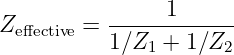
ESR = tan / 2πfc When two caps are parallel the ESR is also in parallel If you crunch the numbers with capacitors that have the same tangent (loss angle) and you put them in parallel you'll see ESR hasn't really changed from just one single capacitor. And no there is no issue paralleling any capacitor values no matter how far apart they are in value. Tangent of say .06 for a film 8.2uF and 4.7uF vs 13uF 13uF .06 / 2*π*1000*.000013 = .7 ohms ESR 8.2uF .06 / 2*π*1000*.0000082 = 1.16 ohms ESR 4.7uF .06 / 2*π*1000*.0000047 = 2 ohms ESR Since the two ESR's are in parallel, that's 1.16 ohms and 2 ohms in parallel 1 / ((1/1.16)+(1/2)) = .73 ohms ESR -
Crossover Capacitors and Crossovers In General
captainbeefheart replied to Curious_George's topic in Technical/Restorations
6.8+6.8 = 13.6 That's going to give you much more of a sonic impact vs any difference between any two polyester capacitors at the same value. I.e Switching to JEM caps will get the speakers sounding more original not because of any special properties other than it's closer to 13uF for the correct output transfer. If you want to parallel capacitors I would parallel 8.2uF and 4.7uF, they are common values and fairly easy to find. 8.2+4.7 = 12.9 Honestly when I test caps of say 10% tolerance they are often fairly spot on but if they aren't perfectly spot on they are on average on the higher side than lower side so the two tolerance differences will probably get you to as close to 13uF as a real 13uF 5% tolerance cap. Same with the 2uF. Using 2.2uF will slightly change the output transfer and that will be more of a sound difference than any two polyester caps compared to one another of the same value exact value. The easiest and least expensive way to get perfectly 2uF is use two standard 1uF values in parallel. Easy peasy and no special non-standard caps need to be found. -
Well I like contrast, the end bells of the transformers are black and the wood I use with white paint is often darker grain wood like Cocobolo, Wenge, Caribbean Rosewood, and Bocote. So I either use black hardware or even just stainless looks nice. I have never used white for hardware. I would think it would be easier to just get cheap zinc hardware and push into cardboard and paint the heads white yourself.
-
https://www.fcpeuro.com/products/bmw-touch-up-paint-a96-mineral-white-metallic-genuine-bmw-51912148489?msclkid=50edab47391c1a01d4d5c85499899792&utm_source=bing&utm_medium=cpc&utm_campaign=BMW Shopping 0&utm_term=4580771607393493&utm_content=Ad group %231 I don't use this specifically, I have it locally mixed and put into aerosol cans. I actually pay $24 per can and since it has base and top coats it's more money than the one I linked but I don't know what shipping is from this company. For clear I recommend using the Spray Max 2k high gloss. It's the best aerosol clear I have ever used. https://www.amazon.com/Spray-Refinishing-Permanent-Surfaces-3680061/dp/B0043B7UQY/ref=asc_df_B0043B7UQY?tag=bngsmtphsnus-20&linkCode=df0&hvadid=79920869194981&hvnetw=s&hvqmt=e&hvbmt=be&hvdev=c&hvlocint=&hvlocphy=&hvtargid=pla-4583520395839480&psc=1
-
I use the aerosol cans and get no orange peel or drips, it comes out nice and consistent and looks great. No cleanup is nice just flip the can upside down and clear the tip before storage. Their white white is called "Alpine White" and is code "300" The paint I use is called Mineral White Metallic and has metal flakes in it and probably some mica flake too. The paint code for that is "A96"
-
Crossover Capacitors and Crossovers In General
captainbeefheart replied to Curious_George's topic in Technical/Restorations
Definitely not a coincidence. 3mH is about the perfect amount of inductance where any lower and the roll-off would be too low but it's just at the right value to not waste anything, cost in size of the autoformer for getting higher inductance is a waste since it doesn't change anything. -
Looking good! For anyone interested in white colors many of the automotive whites are nice, especially the Pearl and metallic. I chose BMW because I liked them the best. There are two main BMW whites, a pearl white with mica flakes in the top coat to reflect light. This does look nice but I prefer the metallic color best. It's just a preference. The BMW "Mineral White Metallic" instead of mica for reflective properties has metal flakes in it. It may have a small amount of mica also because it has some sparkle to it also but at some angles the metallic flakes give it not just a white look but also a slightly sparkly gray tint. The "Pearl White" is definitely more a white white. I can give people the exact paint codes to order if they want. I have it special mixed into aerosol cans so I can spray it since I don't have a spray gun but for the cool guys out there into automotive that may have a pneumatic spray gun can just order the paint in non-aerosol cans.
-
Little Sweetie Forum amplifier project
captainbeefheart replied to henry4841's topic in Talkin' Tubes
The issue with air core is you don't have a core helping you increase inductance, but you also don't have it's saturation curve characteristics. Since you need a lot of copper with an air core it will given the same inductance have higher DC resistance unless it's absolutely massive and not fit inside the speaker enclosure. The thing with cored inductors is as long as you are on the right side of the saturation curves; i.e. no saturation then the core should have minimal to no effect on the signal. I'd prefer to use very high permeability core material and less copper to keep DC resistance low and size it so no saturation occurs at maximum signal level. It will be less expensive, have a smaller footprint and function the same or better. I mean most of us use very low power since our speakers are so efficient so I highly doubt the core is effecting the sound in any audible way. -
Crossover Capacitors and Crossovers In General
captainbeefheart replied to Curious_George's topic in Technical/Restorations
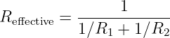
The 3636 goes in 1db steps correct? I don't have any experience with it but that's what it says on Crites. I think measuring from 6db points which is an easy 1/2 turns 1/4 inductance/impedance (-6db) or 2x turns and 4x (+6d) impedance/inductance can make the math easy. But 6db is not exactly double 3db. So you can't just do another 2x (.5x) turns and 4x (.25) impedance inductance. 3db steps is 1.4x turns 1.96x (+3db) impedance/inductance or .7x turns .49x impedance (-3db) You'll just get more accurate values using the 6db measurements and doing whole number maths is easier. Anyway, Yes in theory if inductance was infinite all that matters is the turns and ratio of winding to attenuate. Just like the primary of an output transformer many just go by the impedance ratio reflected by the secondary and ignore inductance, the inductance reactance is in parallel with the reflected load impedance so when the inductance is low enough to reduce the reflected impedance and load down the tube, hence inductance is important factor of an output transformer. With a large enough inductance in the autoformer the same thing can happen. In theory if the inductance is large enough it can be ignored and attenuation is made by the amount of turns. But if the impedance gets low, the inductive reactance is still going to be in parallel with whatever the reflected resistance will be and can increase the amount of attenuation which in our case making a filter works for us. If inductance makes zero difference either way why are we seeing different low frequency behavior from LTSpice? Lower the inductance even more and see what happens, it will roll off at the low end even faster. So yes, inductance does matter, but once it reaches a certain level, and that depends on the reflected impedance of the mid-horn and the inductance becomes large enough the roll off won't change. like 15 ohm with infinity in parallel is still 15 ohms, but 15 ohms with say 65 ohms in parallel will lower the 15 ohms to 12 ohms. And we all know reactance is reduced with frequency. Play around with inductance values in spice. You'll see that going huge with inductance you'll get very little changes in the roll off characteristics because the turns and reflected load dominates, but you'll see when the inductance is lowered and the lower you go the more the inductance will actually move the low frequency roll off characteristics in our favor. I.e. more attenuation of lows. Again going back to the output transformer primary inductance, going with a very large amount of inductance the reflected load impedance will always dominate, but since inductive reactance is in parallel, if you choose too low a primary inductance at low frequencies it will start to effect the reflected load by reducing it and loading down the tube. Make sense? -
Crossover Capacitors and Crossovers In General
captainbeefheart replied to Curious_George's topic in Technical/Restorations
The lower inductance actually will have a quicker slope as shown making the filter more efficient at removing low frequencies. Very interesting. -
Crossover Capacitors and Crossovers In General
captainbeefheart replied to Curious_George's topic in Technical/Restorations
Yup that sounds about right. Crites said larger coil and core so one would assume it had more inductance across the entire winding. You can see the plots start to differ more at low frequencies because the inductance reactance is getting lower and starting to play more of a role with the reflected impedance of the mid-horn since they are in parallel. Interesting. -
Crossover Capacitors and Crossovers In General
captainbeefheart replied to Curious_George's topic in Technical/Restorations
Thank you! -
Crossover Capacitors and Crossovers In General
captainbeefheart replied to Curious_George's topic in Technical/Restorations
What are the two measured inductance of T2A and 3636. If nobody wants to make it public please private message me the values. Thanks!