
John Warren
-
Posts
2263 -
Joined
-
Last visited
-
Days Won
1
Content Type
Forums
Events
Gallery
Everything posted by John Warren
-
I have no hobbies, I'm just an engineer.
-
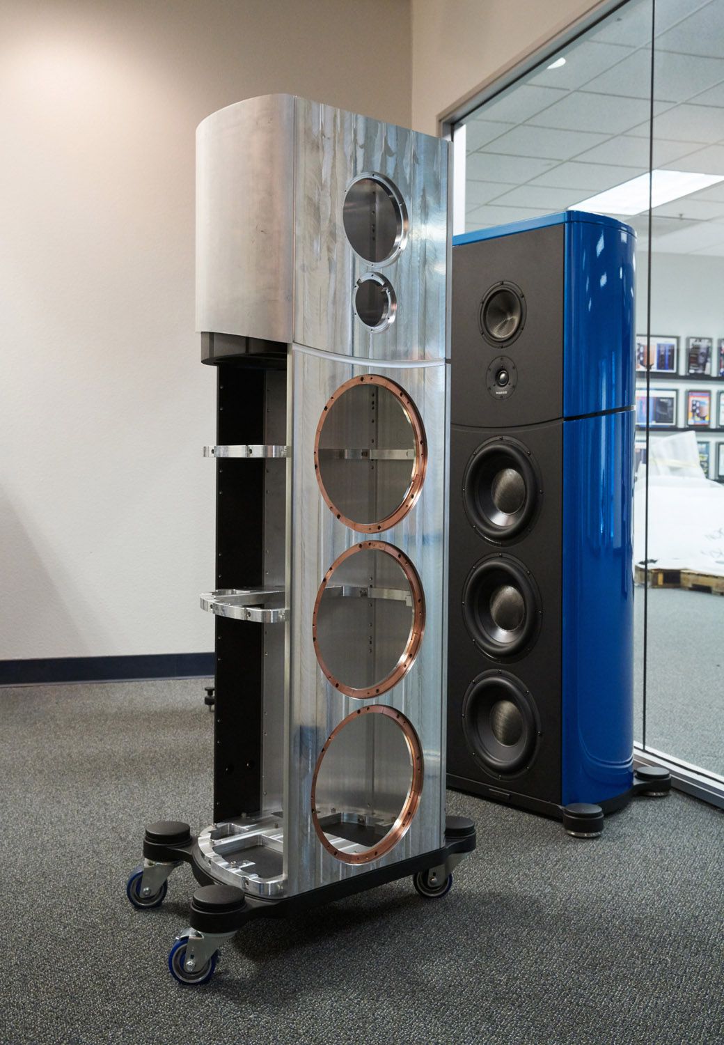
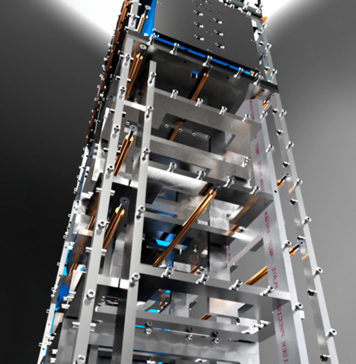
Ignoring the cost, which is considerable for high end audio components, driver entitlement becomes a near reality when the enclosure is rigid. Although the images are from the Magico website, Aluminum enclosures machined from plate stock are nothing new. I heard a pair of JBL L100 clones fabricated from 7/8" Al-plate, milled and assembled using cap screws and Loctite adhesive. It was heavy but easily managed once placed on a dolly. Internal bracing resulted in the overall enclosure being somewhat larger than the OEM version. The difference in the low end performance is hilarious.

-
Entitlement in the audio reproduction "chain" isn't in the electronics or even the loudspeaker drivers, it's in the enclosure materials. And the folks fabricating enclosures out of Aluminum alloy are on to something. It's a "ffs" moment listening to them.
-
99.999999% of audio amplifiers are voltage sources. If transconductance amplifiers were a better mouse trap, the world would have marched to them immediately. Why do you think it did not?
-
The Belle is just better looking.
-
Short of cracking open a 7591 and just looking at G2, the datasheets from all the old suppliers state that Pin 8 and Pin 4, which both make internal connections to G2, are to be externally connected via jumper for "efficient" operation of the screen. The cold resistance between P8 and P4 is 0.2-0.3 Ohm, i.e. a short. So that's got me curious, why the external jumper? I can speculate it's due to the way the grid is made, two sections connected by grid wire that, when operating, develops a hot resistance large enough to sustain a potential difference between p8 and p4, a difference enough to alter the screen grid performance. Anyone actually know?
- 1 reply
-
- 1
-

-
Resistors to improve amp/speaker synergy
John Warren replied to tube fanatic's topic in Talkin' Tubes
This is going to get interesting. -
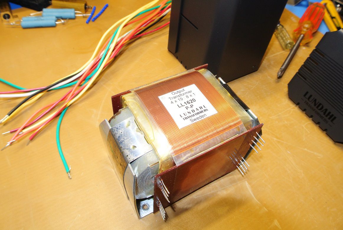
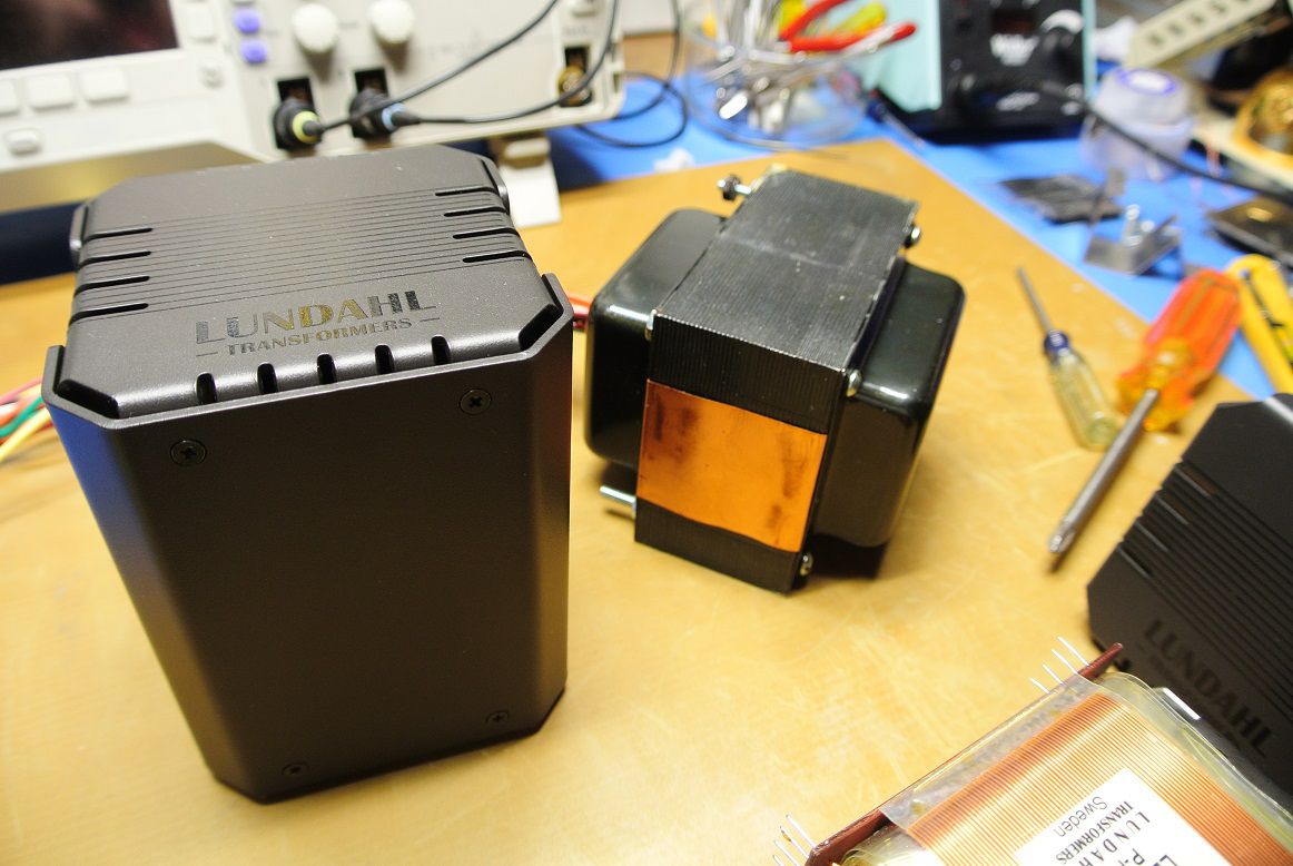
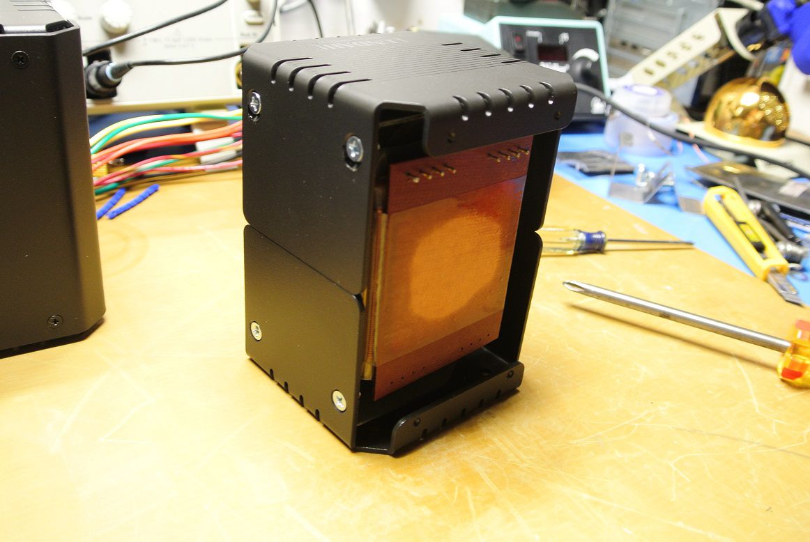
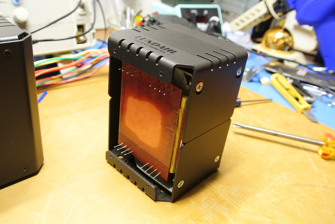
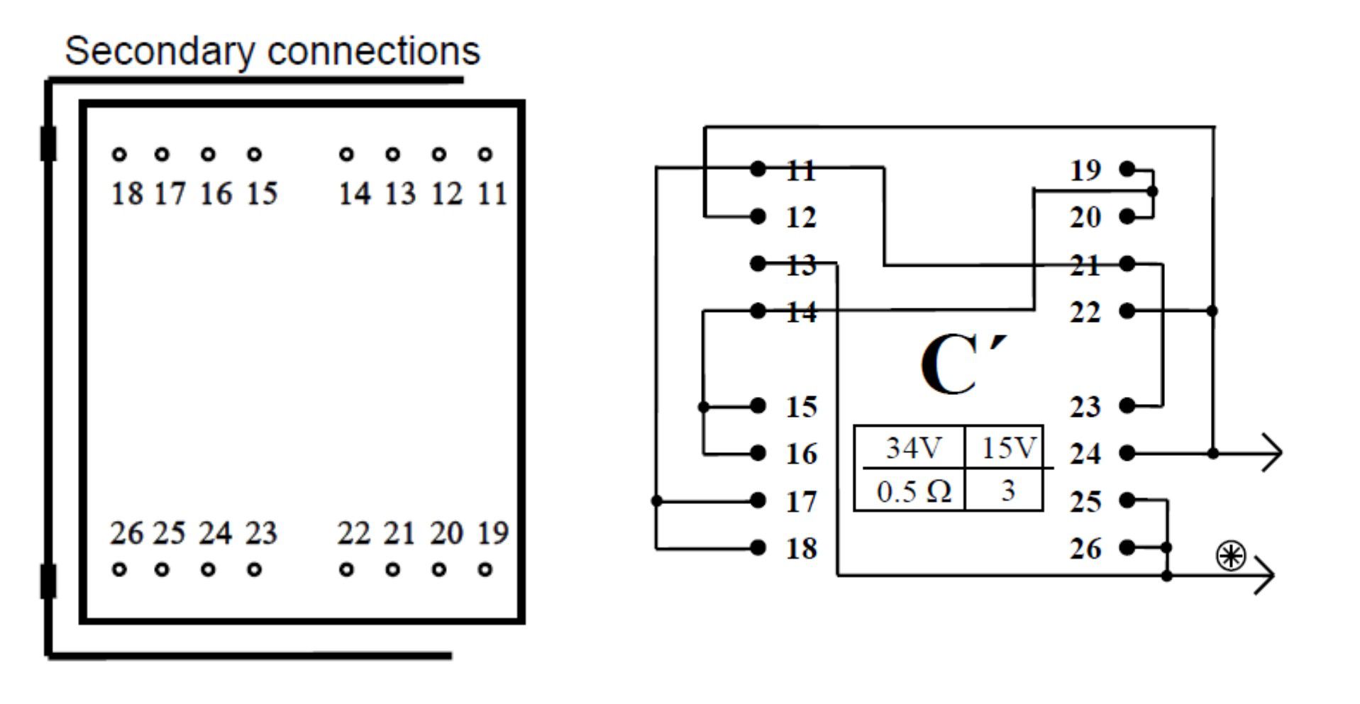
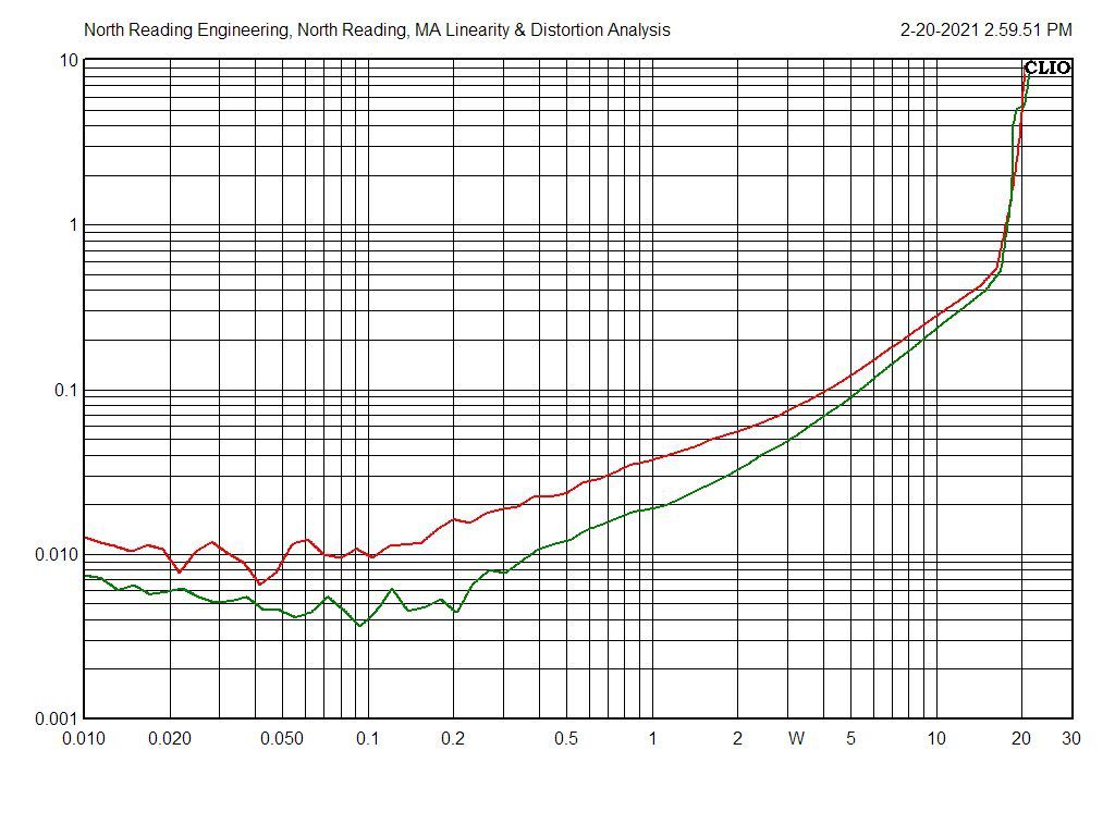
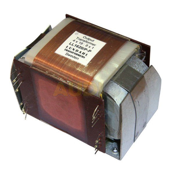
Took some time but the Lundahl units have arrived. They're 25W RMS, 6K primary 4/8/16 Ohm secondary, C-core transformers. Here's the primary side of the output transformer, eight solder pins. And here's the secondary side, sixteen tinned wires. The enclosures are optional, total cost with enclosures is $625 for a pair. The secondary is a bit of a pain to wire. To measure the primary impedance, I temporarily soldered it for an 8 ohm load per the schematic below. GREEN is the primary impedance of the Lundahl with non-inductive, 8 Ohm load and, for comparison, the Hammond 1650PA PURPLE and the Scott OEM output transformer, GOLD. The Lundahl is a bit flatter than the other two. Output tubes are 7591s in push-pull arrangement.
-
Western Electric 300B Tubes are now available
John Warren replied to Jim Gregory's topic in Talkin' Tubes
I have no doubt that vacuum tubes today can be made vastly better than what the OEMs could provide. Vacuum systems, glass technology, materials supply chain are all better. And there still is, today, a large presence in the high power, vacuum tube industry (radar and communications). There are plenty of highly skilled technologist in the vacuum tube industry. Look up, Travelling wave tubes, cross-field amplifiers, Klystrons, Magnetrons. But, is there a business case for such an investment in audio grade vacuum tubes? I would propose no, there is none, too costly and the returns are not there. -
New Mom's use it in baby formula too.
-
is the only water you should use to saturate your solder tool sponges with. Don't use tap water to wipe your soldering tool tips clean, the Chlorine, Fluorine and salts will corrode the plating on the tip and shorten tip life by half. It's literally free at our supermarket (0.99/gallon) with 3 year shelf life. To be called distilled, the total solids content can't exceed 10ppm which is pretty spectacular given your paying about a buck for a gallon. Don't use Di-ionized water either, it will attack the tip.
-
Spent Friday last listening to the Transcendar and Hammond output transformer versions of the amplifier. I have a well broken in set of Sylvania 7591s that I was using, swapping them from one to the other. Speakers are JBL L200s. I also revised the feedback on the Hammond to provide a bit smoother response above 50kHz. Here's the distortion curves for both channels with the Transcendar outputs and Sylvania tubes, virtually identical. There's a leveling off as the power approaches 8W RMS or so then there's a significant rise past 15W RMS. The plates can dissipate 19W RMS. Same tubes with the Hammond outputs. The Hammond is rated for 60W, a much larger core than the Transcendar which is a 22W transformer. And here's the amps How did the sound? Hard to discern a significant difference between the two but I did like the Hammond version better. The L200 isn't that good in the mid range and the bass is "tubby" but, that said, both amps sounded good to my 62 y/o ears. I was plugging a 24-bit CD player directly into the RCAs, no preamp. The distortion curves were taken after my listening so I wasn't entirely biased based on measurements.
-
I'll be giving a pair of Lundahl output tramsformers a go in this amplifier. I'm curious to measure how a C-core transformer measures against the conventional units. The LL1620/PP has the correct primary impedance (6k Ohms), wattage (25W) and max plate current (150mA) into an 8 Ohm secondary load. There's a nice powder coated metal enclosure that can be purchased too. It's almost an exact replacement for the OEM version but, theoretically, a better version. It will require a third set of mounting holes be added to the chassis plate. The advantage of a C-core transformer is the magnetic field is well contained and lower stray flux, no sharp corners in the iron circuit. The coupling between the primary and secondary should be better. But can it be heard? and can it be measured in %THD? .
-
All things are possible.
-
Yes, he contacted me a few weeks ago asking if he could purchase it so I sent it away. I've serviced a couple of his tube amps in the past. I'm curious to get his take, he has many vintage tube amps including some rare pieces. I've have a second Beta built and parts for a third. PC boards and the machined chassis plate have a small price break at three pieces. The amp will produce full power into an 8Ohm load (~12VRMS) and <0.5%THD with an input signal of ~1.6VRMS which allows for DVDs, CDs, tuners are other "line level" outputs including pro hardware. With sensitive speakers the output would be painfully high with a direct plugin of CD player and listener a few feet away. It will require a preamp for a phono inputs. There's a separate level adjust for each channel and a stereo balance potentiometer. There's also a line level center-channel output RCA jack with level adjust too. I always wanted a center-channel in my setup and now I've have one. I have the preamp board on order but have yet to consider how it will be packaged. I'm less excited about tube preamps. I've designed solid state preamp boards with greater than 100dB distortion free output.
-
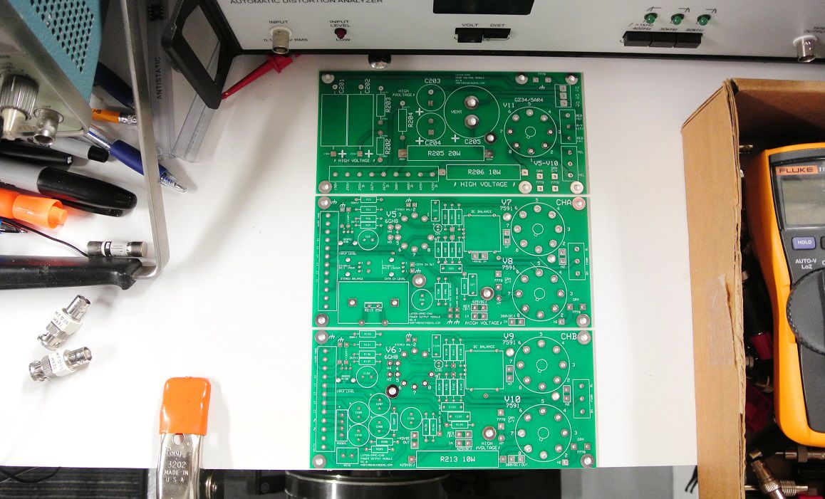
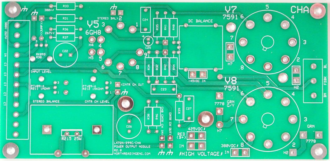
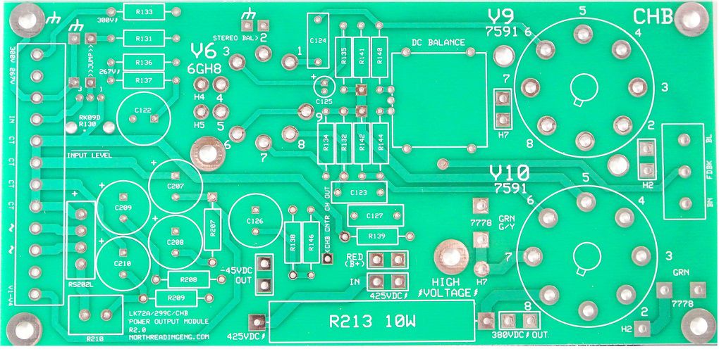
Here's the beta board set. The boards are designed using a package that links the schematic to the layout. So you first layout the schematic and all the painful details associated with the size of the leads, component body, wattage, pin identification and then commence with the layout. Dual traces (top and redundant bottom trace) are dark shadowed in the photo. Here's closeups of each board
-
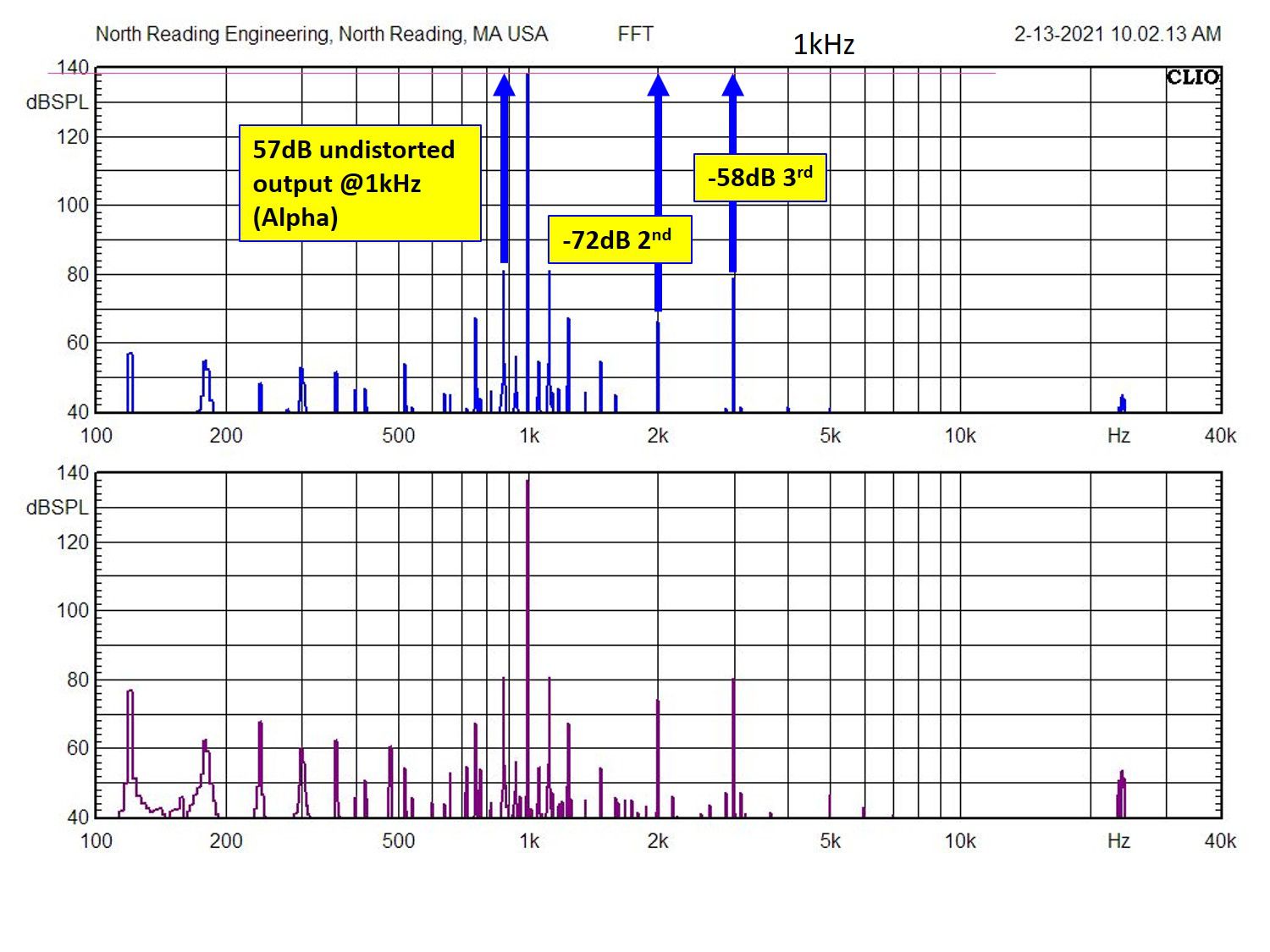
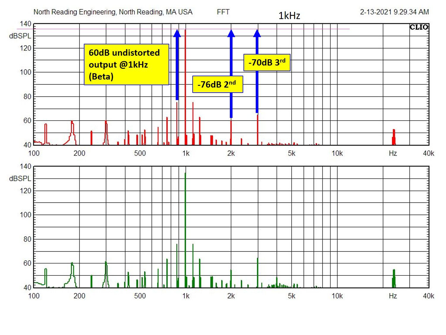
Some performance data comparing the two designs. Here, the analyzer was calibrated and left alone, the amps then measured sequentially. Same tube types and manufacturers (JnJ) but the alpha tubes have more time on them so not entirely an apples 2 apples comparison. DC balance was checked and adjusted before the test. 1kHz %THD. Both channels in the beta are similar in performance. FFT of the alpha unit, both channels (CHA is top): FFT of the beta (CHA is top): So some differences with beta being a bit better but not dramatic differences. Both sound great and are fun to use.
-
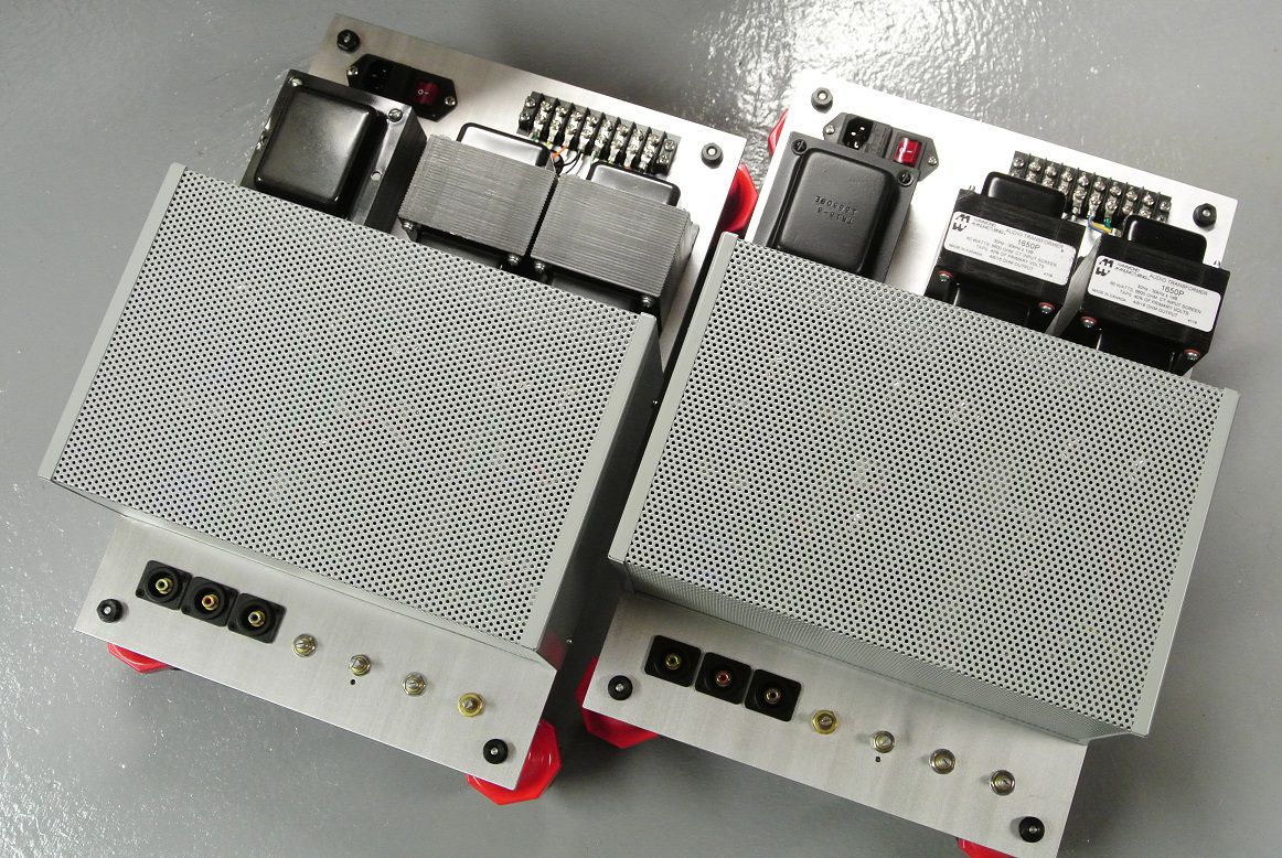
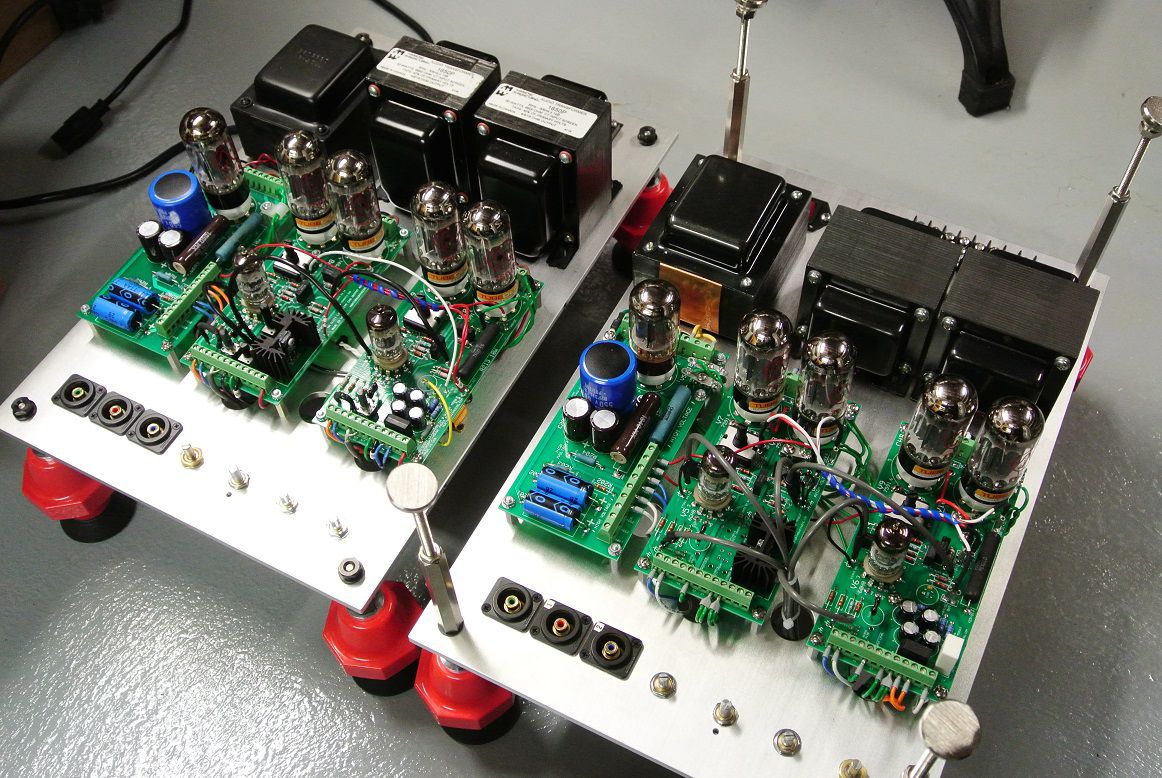
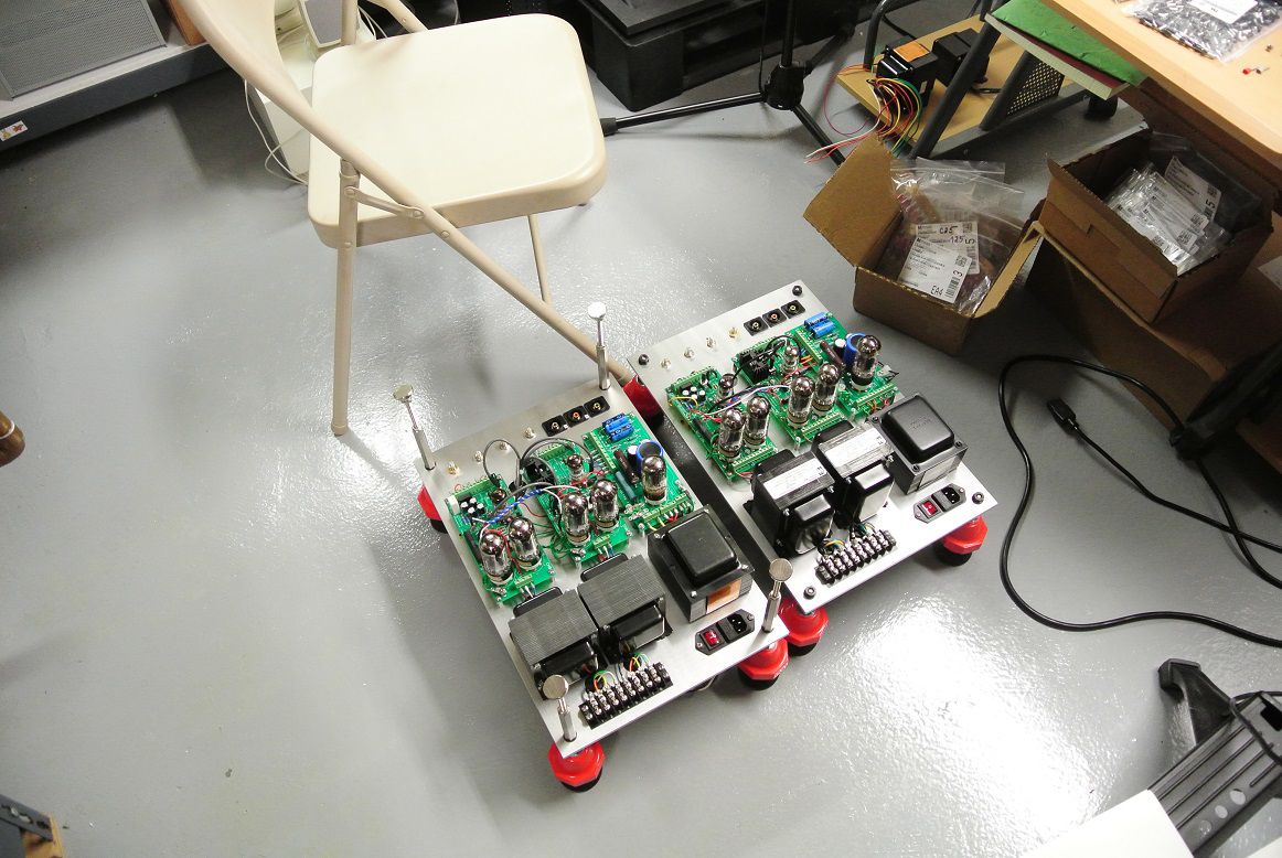
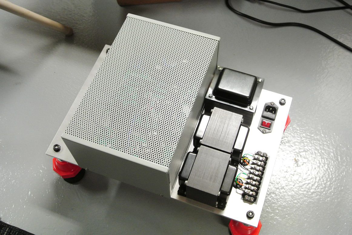
Getting back to the Scott clones, here are the two amplifiers, the one on the left is the first iteration (i.e. alpha) using the first set of PC boards I designed for the project. It uses the Hammond output transformers. The second iteration (i.e. the beta) is to the right. That guy uses nice wire to board connectors a bit better trace layouts especially with regard to handling traces that drain back to the c/t. It also uses the Heyboer Scott 299C replacement PS transformer and the Transcendar 299C replacement output transformers. From the photo below you can see these are not small. Here's the Beta with cage installed. It went out FedEx yesterday so let's see how well it survives the trip to Chicago! The chassis plate is 1/4"thick 6000 series Aluminum and all the fasteners are good quality.
-
Thanks JC, I'm pleased to hear they're working well. When I was done with JC's 250 amps, they both measured well, low distortion and ruler flat bandwidth. After a couple hours of running hard and loud, both were cool. I was pleased when they went out the door. When JC hooked them up to his rig, he's initial impression was they were hard on his ears. Apparently a wee-bit of fiddling with the setup got them to behave. I'll post a few photos of the work I did on JCs amps in the solid state forum.
-
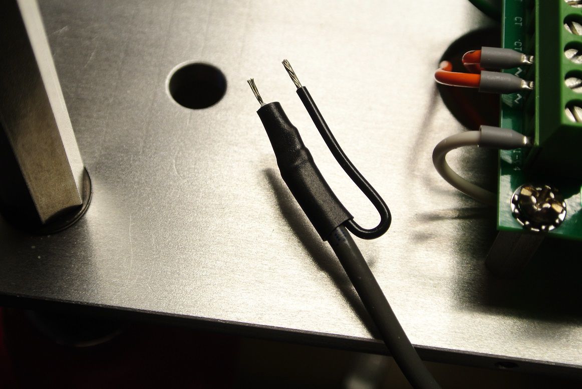
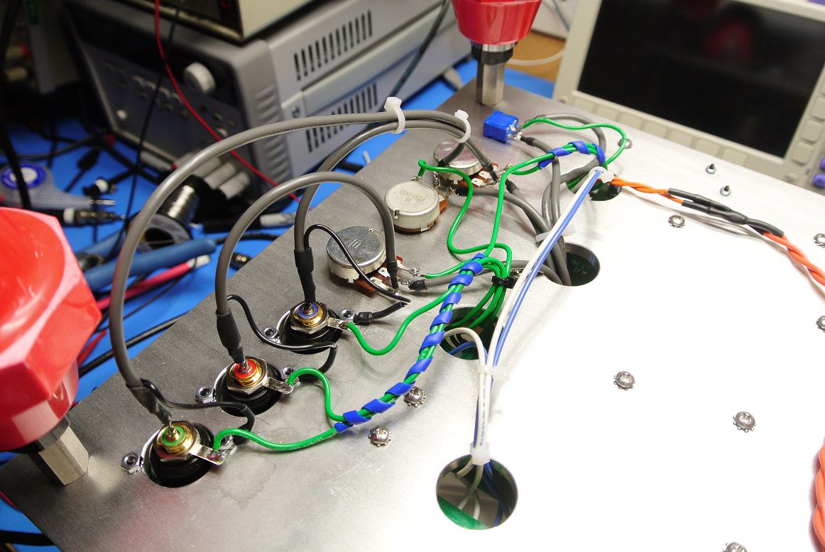
Thank you. The original amp is a two prong whilst this thing is a three-prong so there's now a "chassis" ground and "0V reference" (i.e. the center-tap). On the early McIntosh solid state amps the small signals were handled using single conductor instrument cable with the shield drain lead connected to the chassis at both ends of the conductor, the lead break-out was connected to the shield braid using a small crimp clamp and then the entire end of the conductor insulated with shrink. I've followed that approach here, the shield drain is connected directly to the amp chassis. On the RCA input side of the amp, the ground sleeve is actually a 0V reference and is handled differently, it's connected directly to the PS transformer center-tap. That's what's going on here, the green leads are 0V references, the black whips are chassis ground connected. The point in all of this is to make the amp as quiet. My take is it worked.
-
Your amp was the inspiration Mark!
-
It's a stand alone "basic" amplifier with CHA and CHB input level adjusts, a Center channel out level adjust and stereo balance pot. I actually did design a preamp board. I can duplicate the entire amplifier, including the tone controls. I designed the preamp board and ordered all the parts for the build, just need to order the board (the entire LK-72A preamp is on a single board!).
-
I'm pleased you find something of interest here! I'm using a CLIO 12 24-bit analyzer @192kHz sampling for distortion analysis. It's a high precision FFT analyzer with a wide range of input signals for analysis. I also have Rohde & Schwarz UPV, Krohn-Hite and Keithley analyzer. I can certainly provide FFT spectrum but find %THD to be a pretty good indicator of amplifier capability (as plotted above). And yes, it's a HH Scott LK-72A/299C copy and you won't find this on Ebay.
-
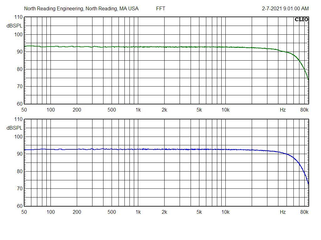
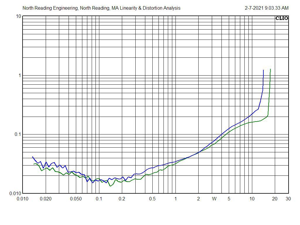
CHA and CHB bandwidth with the Transcendar LK72/299C output transformers. Some improvements over the Hammond units. -3dB is about 40kHz for each, not bad for a 60 year old design. The plots look similar to the OEM responses too. Input signal is 200mV cross-correlated MLS. Level pots open wide. %THD at 1000Hz below for each channel. The uptick in the distortion curves is associated with oscillation pulses that occur in the output when the tubes approach the design limits.
-
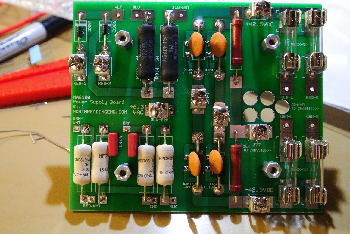
Being true to the design original has it's problems. There are two 100uuF Silver Mica caps in the OEM units and one is in the feedback circuit sourced from the output transformer secondary. The amp will oscillate using the Mica cap in the feedback circuit and cause the output tubs to red plate. A 100uuF MLCC however completely defeats the oscillations. It's the little yellow one in the photo below. An explanation may be in how the caps are constructed.