Cut-Throat Posted May 8, 2003 Share Posted May 8, 2003 Well I returned from my Montana Fishing trip last night and finally had a chance to fool around with my Moondogs. Thanks for the various suggestions. - I did unhook the pre-amp from the Dogs and with the Volume all of the way down on the pre-amp the hiss was noticeable only by putting your ear up to the tweeter. With the pre-amp connected and the volume turned to about 9 O'Clock there is a slight hum coming from the woofers (with no music playing). There is also a slight hiss coming from the tweeters. With no music playing and the Volume turned to about 12-1 O'Clock the Hiss and Hum is audible from across the room. At normal listening levels with music playing the hiss and hum is not noticible at all. I just would like to know if my level of hiss and hum is normal. Someone suggested to me in an e-mail that this noise is tube-related 99% of the time. Anyone have this experience? Quote Link to comment Share on other sites More sharing options...
edster00 Posted May 8, 2003 Share Posted May 8, 2003 I do have a very slight hum from my K-horns with the volume on the preamp turned down as far as it will go. I did not hear this hum when I had the 'dogs hooked up to my Cornwalls. I cannot hear the hum at all with music playing. I don't hear hiss. If you adjust your hum pots for the lowest volume hum from both speakers is the hum volume equal from both speakers? Do you have any extra tubes you can swap out and see if they make a difference? To be honest I have't tried turning the volume up to see how loud the hum gets, it just never occurred to me...I would expect it to get louder. Quote Link to comment Share on other sites More sharing options...
Erik Mandaville Posted May 8, 2003 Share Posted May 8, 2003 Hey, Cut Throat: I have a cure! Play some music! Honestly, The speakers we are using are among the most sensitive and efficient available. The Moondogs have an AC filament supply on the output tube, for which the hum/null pot offers reasonably good relief....but in the case of highly efficient horns, perhaps not complete relief. This however is not always the case with single ended amps like these. YOu once mentioned your 300B amplifier (wasn't this you, Cut Throat?)was more free of hum than the Moondogs. That amp may in fact use DC on the filaments, and this done by way of a full-wave bridge rectifier and filter circuit. Your problem does not sound out of the ordinary to me. There are couple of things that might help: 1. Be sure the circuit ground on the chassis is thorughly grounded to BARE METAL. The Moondog construction manual does not make note or mention this important factor. I've done this to my own amps, as well as those of a friend. You need a good ground. That said, the other option is to completely lift or float the circuit ground so that it is only grounded on the preamp end. This last thing is what ultimately did the best for me, but at least make sure the chassis ground is tightened snugly, and that the ring terminal is making contact with bare metal. After you've done this, try lifting the preamp earth ground with a two-to-three prong cheater plug. 2. You can try adding an additional 10,000mfd in the 6SN7 rectifier/filter section. This might help, and might not do a thing. 3. If you have a schematic, you can audition the amplifiers without the cathode resistor bypass capacitor in the input stage. This is 'C5' on the schematic, and is a little red electrolytic capacitor. This may help reduce the gain (probably only very slightly)and subsequently this hiss you are hearing if it is bothersome. I actually like hearing a little bit hiss wihout music, since it lets me know my tweeters aren't shot or blown or malfunctioning or otherwise not feeling well. 4. Did you short the inputs on your amps when you didn't have the CD player connected? Take an old RCA jack, and solder a lead between the center pin and ground or body of the jack. THEN see how what that does to the hum. Check to make sure the jacks on the interconnects from your preamps to amps is snug and tight on their respective inputs/outputs. Check the same thing on every jack and cable in your system. Are you certain your cables are in good shape? Check to make sure that shield connections on the insides of the jacks are good -- a bad ground on a cable is just another bad ground in the entire circuit, and can cause hum. 5. Get some 6A3 tubes, and use a dedicated filament transformer to supply the 6A3 filaments with DC. You would need to make some other minor changes here and there, but it would be easy...and probably much less prone to hum than the AC filaments on the 2A3s. (Sorry, I have to say this....but don't do it if you're not quite sure -- no offense intended, please understand that.) 6. Make sure the ground connection on the RCA input jack on the amplifiers is making a good, solid connection at BOTH ends. Check to make sure that all solder joints are mechanically sound, and not just held together by a poor solder joint. If the safety ground on the chassis is bolted under one of the other transformer nuts, make sure that is tight, as well. 7. Put some extra tension on the tube pins, themselves. If tubes seem to pull in and out really easily, they may also be making poor contact. Push the pins together in each tube pin hole so that they grasp the tube pins securely. (For me I have to say: be sure power supply capacitors are discharged before hand). 8. Try making an active shield of the bottom panel on the amplfiers: cut a piece of wire about 4 inches long, and strip each end back about 3/8". Crimp and solder a ring terminal on both ends. Put one on the circuit chassis ground, and route the other through a carefully drilled hole in the bottom plate. Locate this hole close to the existing hole in the closest corner. Put a rubber grommet in the hole; making sure the hole is big enough to pull the ring terminal through when you want to remove the plate. Then carfully remove the paint from around the appropriate hole in the bottom plate, so that the other ring terminal will make contact with bare metal. Put everything back together, and you will have some additional sheilding against RFI and EMI. I have this on my amps, and it help tremendously -- it was one of the main ways I cured some buzz and hum problems I was having. 9. Try this seemingly silly thing: Wrap some aluminum foil securely around the input jack (with the interconnects in place), and ground one end of the foil to the chassis. You don't want to leave this obviously, it's just to help troubleshoot. Ok....enough. I hope maybe some of this helps. How do things sound with quiet music? I mean, are you getting lots of nasty buzzing and hum with even light music? If not, the problem isn't too bad. Get some extra tubes to see if those help. I recently auditioned some KR 2A3 tubes, and they were quiter than my Sovteks. Get a couple of different rectifiers to try,too. Rest. Erik Quote Link to comment Share on other sites More sharing options...
Cut-Throat Posted May 8, 2003 Author Share Posted May 8, 2003 Erik, You have given me a weeks worth of work! - Thanks for the suggestions! -- Yes I believe the Billies do have DC on the Filaments and they do have the Bridge rectifier. And it was me - Yes the Billies are a quieter amp (Not surprised as they were reviewed as being the quietest 300b) I have plugged in some RCA 5692 Red Base in them and the noise level is the same. Actually if I am listening to music at any volume level the hiss and Hum is not noticible. I may fool around with the ground tomorrow just for the hell of it. These Moondogs have the Ultimate Parts upgrade and I have got to say that the tube sockets (which are the high buck ones are the loosest sockets that I have ever seen. Some of my other amps the tubes are so tight you have to grunt to get them out. These sockets are so loose that the weight of the tube itself is almost enough to seat them. I may try to tighten the pins a bit. There may be nothing amiss at all, I am just making sure. Thanks for all of your suggestions. I may sit on a few of them, as I don't want to modify this amp too soon. Quote Link to comment Share on other sites More sharing options...
Erik Mandaville Posted May 8, 2003 Share Posted May 8, 2003 One day, I will have the ultimate upgrade! I've gotten a good start though with my beloved Jensen Capacitors! ok, ok, maybe 'beloved' is a bit of a stretch.... Some the the looseness on the pin sockets may have something to do with the fact that the sockets are machined Teflon, and therefore have a pretty low surface tension compared to ceramic or phenolic sockets. The plastic octal sockets on my Moondogs grab the dang pins so tight, I have accidentally snapped off the guide pin on the tube, itself. The contacts on yours are silver plated, and there are two wafer-like prejections within each tube pin hole that can easily be pushed more closely together with a very fine screw driver or needle tool. also check the ground bus connections inside the amplifier. There are quite a few leads referenced to ground, and they all need to be mechanically sound. These are usually done with black insulated wire. My amps have a dozen different colors, since I don't worry about the color coding. But if your amps are fairly stock, then most grounds should be done with black wire. Make sure the B- connection is good, too. The circuit requires this, and can function poorly or make noise if this isn't done with care. Also check the ground on the input/driver heater supply. There will be a wire from the negative side of the 10,000 mfd capacitor to ground. Heck! can you post a close-up of your amplifiers on this forum? Just don't ask me to do the same! I know absolutely zero about how to do that. I have so much to learn about this digital stuff!!! I can type fast enough, but I'm an absolute snail when it comes to understanding computers. It took me forever to first register onto this forum! Enjoy your Moondogs, I'm sure you can get that hum quieted down a bit. Do you have any less sensitive speakers around? try hooking them up to see if things are quiter. Check too the connections on your crossovers -- tighten all of them, as well as the connections to the drivers. They use friction fit terminals, and there might be one or more that is excessively loose. Ok, I can't think anymore tonight. It's so close to summer, and students at school are getting really kind of crazy. Suddenly high school seniors are acting like middle school kids again! They're great kids, though...just tiring by the end of the day. Take it easy, erik Quote Link to comment Share on other sites More sharing options...
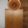
Cut-Throat Posted May 8, 2003 Author Share Posted May 8, 2003 Erik, OK - here is a Picture of one of my Moondogs Undersides. If you need a more detailed view just ask me. Quote Link to comment Share on other sites More sharing options...
Tom Mobley Posted May 8, 2003 Share Posted May 8, 2003 Cut-Throat, Pretty nice-looking stuff. Maybe someday.... Tom Quote Link to comment Share on other sites More sharing options...
Erik Mandaville Posted May 9, 2003 Share Posted May 9, 2003 Cut Throat: You bet you have hum! There are a number of problems with your amplifier that I can see from the picture you included. 1. Moondogs are designed to have a full-wave bridge rectifier and smoothing filter for the input and driver heater supplies. YOURS IS MISSING! This means you are getting a considerable amount of AC imposed on the 6SN7s, and some of that is bound to get on the grid of the tube and induce hum. 2. The 2.5 volt filament supply that goes to the hum pot is not twisted, nor is the much longer lengths of yellow wire that connect between the hum pot and the 2A3 filaments. This seemingly small detail is significant, however. I worked on another Moondog for a friend that had the same problem, and twisting ALL AC carrying can help significantly. 3. I don't know that the heck is up with the color coding on your output transformer. I am very familiar with the color coding of the taps for 8 and 16 ohm voice coil loads (speakers, that is), and I can't make sense of what the builder of your amplifier did. The hum you are hearing must be quite excessive, and it is good we have started to deal with the issue. Rectifying the AC on the input/driver stages will make a big difference, and re-doing the entire filament feed and hum pot circuit will only make things better and quieter. 4. There should also be a dropping resistor (composed of two paralleled power resistors)on one leg of the AC that feeds the 6SN7 heaters. This is there to lower the voltage to just around 6 volts. So there are a few things that need to be done on these amps, for sure. Do you have the schematic for the amplifier, and do you know how to construct a full-wave bridge rectifier and filter circuit? If not, let me know what I can do to help, I enjoy the problem-solving and repair. If you're not sure how to do this, DON'T take it to some tube repair place!!! They will likely charge an absolute fortune to make these simple repairs. I'll help ya for free! There were people who have done the same for me, and I wish to carry on that tradition. These are truly fine amplifiers, but I don't know what was going on with the person who built yours? Maybe there was some sort of purest, less is more philosophy happening. In this case, though, the 'less' is causing problems! Erik PS: Are you able to take a close up of the output transformer wiring? This is the colorful snarl of wires next to the choke in the upper left-hand corner. Quote Link to comment Share on other sites More sharing options...
Erik Mandaville Posted May 9, 2003 Share Posted May 9, 2003 And: You are also missing the small, red electrolytic bypass capacitor that is supposed to be on the input stage. This is not such a big deal, since it doesn't do that much, anyway! Work through the other issues, and you will have a much quieter and enjoyable amplifier. ....There are some strange things going on in there. The manner in which the coax input is connected to the grid of the first 6SN7 is strange. There is a yellow lead attached to the end of the coax, which is in turn connected to the tube socket pin. Much better to rewire this directly. It won't take long, and is an easy fix. ...gotta get ready for work! I was just really curious about what the inside of your amps look like. Other then the things mentioned above, they seem to be in fine shape. Parts of a full wave bridge can be found at Radio Shack for cheap. The only thing, is that you need a 10,000mfd electrolytic cap, and the biggest they usually have in the store is 4,700. A little more is beneficial in this case. Erik Quote Link to comment Share on other sites More sharing options...
Cut-Throat Posted May 9, 2003 Author Share Posted May 9, 2003 Hi Erik, Thanks for all of your help with these Moondogs. First off, I want to assure you that I have complete confidence in your technical acumen. I followed the Edster thread on his Moondogs and you did an outstanding job. I would like to try to fix these Moondogs myself under your direction. Mainly for a few reasons; 1.) I am deathly afraid of shipping audio components. I always hold my breath. I do not have factory boxes or packing materials for these Moondogs. I have seen the ravages of UPS. 2.) I would like to learn something from you and would also feel better about the Moondogs. A bonding with them so to speak. 3.) I have invested in a few electronic tools in the last few years and the DIY thing. I have a relatively new Xtronic soldering station with digital temp control that is really neat to use as well as Digital Mutli-Meter. 4.) I enjoy putzing with audio equipment. I needed another amp like a hole in the head. But do enjoy messing with them. Your technical skills are not in doubt. Mine Are. Here is where I am technically. 1.) I was an Electronics Technician in the Navy, but slept through most of the classes. I did glean enough info to understand Ohms law and to not kill myself. 2.) I have built - From kits the AE-25 Push Pull Amp. The AE-3 Pre-amp, The 300b Billies, a Couple pairs of speakers and some crossovers such as the Type A. My soldering skills are pretty damn good if I do say so myself. 3.) I do not have any Schematics or Parts Layout of the Moondogs. But I am able to take Voltage, Resistance measurements with a DMM. Something like Measure the Voltage between pin 4 on Tube A2 to Ground. So if you wouldnt mine walking me through some of these Mods (with some potentially very dumb questions) I would very much enjoy this. This would be even a bigger challenge for you Erik. Kind of like talking down an aircraft with someone else at the controls. I can supply you with very detailed digital photos as I have a good digital camera with macro capability. I will take some photos today and e-mail them to you of the area that you requested. Let me know if you need any other close-ups. Thanks a Bunch! Quote Link to comment Share on other sites More sharing options...
leok Posted May 9, 2003 Share Posted May 9, 2003 cut-throat, sheesh .. nice looking amp, but like Erik says .. some strange stuff going on. Erik knows what he's doing. leok Quote Link to comment Share on other sites More sharing options...
Erik Mandaville Posted May 9, 2003 Share Posted May 9, 2003 Kevin: Excellent! you can do this yourself, for sure. And boy have I made a bone head mistake or two or three or four -- and learned not to do the same thing again. The mistake either hurt (ZAP!) or was expensive to fix, and so learned a little at a time. I'm just so familiar with the Moondogs, and there are lots of guys like Leo and Craig and others on this forum who can help you get your new amplifiers sounding the way they should. We can take each section at a time, and you can sort of make the repairs in tandem. First Up -- Rectifier circuit for the 6SN7 heaters. 1. With the amplifier upside down as they are in your picture above, look at the two blue wires coming up through the chassis hole (the power transformer is on the other side). This is located just above and slightly to the right of center. Those two leads are the AC supply for the 6SN7 heaters. There is a 3rd wire there (blue with white stripe), which is taped off and unused on the stock amp. We won't be using that. Cut that off about 1/4" away from where it is soldered to the solder lug. Use de-soldering braid (Radio shack -- get about two rolls!)to remove the excess solder, and pull away the remaining short length of wire with long nose pliers. Take off that blue and white striped wire, leaving the other two solid blue wires where they are. There is also a black wire connected at the same place the blue and white striped wire was, which is most likely connected to the ground bus -- leave the black wire in place, since we will use that for the negative end of the rectifier. Do you follow this? (This might take up a good bit of space...maybe we should work it out via email so others don't have to see and read it all? Then again, it's handy for me to be able to click back and forth between your picture and what I'm writing. We could easily get that rectifier circuit finished this weekend. You can get the above steps done at your convenience, and then make a trip to Radio Shack to get the following: 2) (each)Bridge rectifier: 4amp at 50 or 250 volts. This looks like a little black rectangular box, about 1/8" thick. It will have 4 leads coming out of one side. The two middle ones are the AC input, and the positive and negative will be marked accordingly. 2) (each) 4700 mfd/35 volt electrolytic capacitor (about $5.00 per)These are polarized and need to be connected correctly or they can go 'POP!' Kevin: The stock Moondog capacitors in this position are 10,000mfd caps. With DC and 4700mfd, you will notice an improvement. If you want to order the same value as on the schematic, you can prepare the blue wires as above, and we can go on to another thing. The way I want to do this right now, is to NOT use the dropping resistors on this heater supply. I took mine out, and things work fine; voltages are good, etc. I'll tell you more why I did this later. The resistors can always be added at another time if you want. 2) (each) rolls of desoldering braid -- we won't use too much of this since what needs to be done to your amps is install rather than remove parts! --Also pick up a roll of Radio Shack solder, just standard 60/40 stuff .032dia. *Use your iron good and hot, which is much better than not hot enough. Too low a temp. causes components to overheat internally. Erik Quote Link to comment Share on other sites More sharing options...
NOSValves Posted May 9, 2003 Share Posted May 9, 2003 Erik, Thanks for the slight mention there. But when it comes to Moondogs I leave the Tech support to you and Leak ! I have yet to ever have a pair to play with so he is much better off with you 2 fine gentlemen guiding him ! I enjoy reading what you guy's are finding as you mod and play with them. Sounds like you guy's are making some serious ground with your changes. Cut throat It sounds to me like you will have no problem fixing these yourself. Craig Quote Link to comment Share on other sites More sharing options...
Erik Mandaville Posted May 9, 2003 Share Posted May 9, 2003 Kevin: Your amps are correctly wired for 8 ohms. I just normally preserve a bit more of the colored insulation when making those connections. At least the leads are left reasonably long, which makes any changes down the road a bit easier. Lets leave those alone for now, assuming you are using 8 ohm speakers. What speakers are you using, anyway??? I never bothered to look! Erik Quote Link to comment Share on other sites More sharing options...
Tom Mobley Posted May 9, 2003 Share Posted May 9, 2003 Don't even think about taking this to email! I want to read it all. It'll be a great learning opportunity. Tom Quote Link to comment Share on other sites More sharing options...
Erik Mandaville Posted May 10, 2003 Share Posted May 10, 2003 Ok, Kevin: There it is: 'C5' (on Welborne schematic)is the cathode resistor bypass capacitor on the first 6SN7. What we can see of it is just it's shiny silver top, reflecting light. I was looking for something red, since its body is that color. So this is good. Honestly, though, the capacitor does not do a great deal for the circuit. It may subjectively increase gain and perhaps a little more low-end response. Leok took his out, which I also tried. Either way, left in or removed, you will do fine. I'm just going to post the next steps you will need to do, and you can do them (or not) at your convenience. You may also need some extra hookup wire for the hum pot to 2A3 heater connection, as well as for slightly longer wires that will go from the new rectifier you will build. If you don't have any, Radio Shack sells solid copper 18AWG that works well for point-to-point. Insulation can begin to wrinkle quickly if you don't solder neatly and fast, however. But it will work fine. Or choose whatever wire you want. Please trust I will give you all part values directly from the schematic. The filter capacitor you need is a 10,000mfd electrolytic rated for at least 10 volts. Rest assured that I will not just randomly make them up! There are other Moondog owners here who can confirm this. Rectifier construction part II With the blue/white stripe wire disconnected, make sure the black wire that is also attached to the same solder lug (as the blue and white)has or goes to or has continuity with ground) Leave that black wire in place. Use some electrical tape or a small wire nut, and cover the exposed end of the blue and white striped wire. On the two all-blue wires, you will also see attached a white wire on one, and a black wire on another. These go to the 6SN7 heaters. Since we are going to use DC on the heaters, you need to disconnect the white and black wires from where they are connected to the blue ones -- preserve as much of the length of these wires as possible. Leave them attached to where they connect to the tube pins. Make sure all areas that had been previously soldered are as clean and rosin free as possible. YOu can use a small piece of fine sandpaper or an x-acto blade to assist here. Connect Bridge Rectifier: Look at the markings on the rectifier. The two inner leads are the AC input connection. Those to either side are the pos. and neg. output that will go to the heaters. Orient the rectifier so that the side marked negative lines up with the black wire to which the now unused blue/white wire was formerly attached. You may have to turn the rectifier upside down to do this. Carefully! bend the rectifier leads as needed to align them properly with the the two blue wires (AC connection), with the black wire (neg.), and with one unused solder terminal(pos.) Use long nose pliers to bend the rectifier leads around and snugly against each of the four solder lugs mentioned above. With whatever capacitor you wish to use (10,000mfd/10-16VDC), connect the negative side to the negative terminal of the rectifier. *Note: on an electrolytic capacitor, polarity is indicated by a stripe running along the body with arrows that point toward the minus side. The positive end can be identified by a concave indention that runs all around the capacitor like a shallow channel. Attach the positive side of the capacitor to an unused solder lug just to the left (in your picture above)of the two blue wires. Do not solder yet. Test to see if the black and white wires that used to be attached to the blue ones will now reach the points they need to attach to the rectifier. The white wire should go to the (+) and the black wire to (-) side of the rectifer. If they do reach adequately, strip (use wire strippers)about 3/8" of the insulation on each, and crimp them snugly around the respective + and - rectifier terminals. If the white and black wires DO NOT properly reach the rectifier terminals, do not force or try to stretch them. Attach a new length of wire to complete these connections. Go over the wiring you just did, making very sure you have the polarity of both the capacitor and rectifier correct. If all looks good, solder these connections in place. Melt the solder sparingly but completely over the joint, using the heated joint to encourage the solder to melt, not the heat of the tip of the iron applied directly to the solder. Make sure the tip is clean and freshly tinned. I use emery paper or a damp paper towel or sponge to clean my iron as I work. I dirty, carbonized tip is inefficient. You now have provided your 6SN7s with a much cleaner and quieter heater supply. This was very likely the main source of the hum you heard. It would also be very adviseable to re-do the wiring on the hum pot. That will follow this afternoon. My own plans this morning are to do some work on an old Scott tuner I may decide to buy. Please let me know if I can help in any way... I hope I have written clearly for you, Kevin! Erik Quote Link to comment Share on other sites More sharing options...
leok Posted May 10, 2003 Share Posted May 10, 2003 Erik, Kevin, The 6SN7 heater circuit is pretty sensitive to noise (mostly hum). Kevin, C9 IS a 10,000 uF, 10V Electroytic. Go for it. It's cheap and effective. In this case you want the most capacitance for the $ and that's electrolytic. I don't know the story on those 6SN7s and their sensitivity to heater noise. My 6922s don't seem to care what's on the heater as long as it's electricity. I guess tubes aren't all the same. leok Quote Link to comment Share on other sites More sharing options...
Erik Mandaville Posted May 10, 2003 Share Posted May 10, 2003 Thanks for you input, Leok! Your contribution is always very much appreciated. My feeling on this, is that output tubes are less sensitive to hum issues than input stages, so it's easier to get by with AC filament supplies on tubes like the 2A3. In that the input and driver stages are associated with much smaller signal levels, I (just my opinion)think it's a good idea to use DC if possible. I am confident this rectifier circuit will help things, although it may not solve everything completely. I believe there was a reason Ron W. opted for a rectifier circuit on input/driver heater supply, and it wasn't just a random idea to throw in. I built a preamp some years back that used AC on the heaters, and that thing was plagued with all sorts of noise and hum. It's possible to sometimes use snubber capacitors to help reduce hum, but I have always thought of that as a sort of bandaid for a heater supply that would really benefit from a simple DC source. If a center-tapped filament supply is used, it can be effectively grounded. Still, if there is the possibility of leakage between heater and cathode on an indirectly heated tube like the 6SN7, the chances that a small amount of AC can get on the grid and cause hum increase. Again, speakers of such high sensitivity only add to the problem. My amplifiers are really quite quiet, but I do have a very low level hum with my ears close to the speakers. However, the kind of music this system produces makes the tradeoff well worth while. Remember too, Kevin that your 300B amps use DC, and you described that amplifier as quieter than the Moondogs. There just has to be a correlation here! Let me know how things go, and if anything I have written is not clear. I'm trying the best I can, but it's detailed writing, and all I have to go on is a picture, ya know! Quote Link to comment Share on other sites More sharing options...
edster00 Posted May 10, 2003 Share Posted May 10, 2003 FWIW, here is a photo of one of my Moondogs that Erik worked his magic on: If I did this correctly you should be able to click on the photo to see a larger version in a new browser window. The larger photo will probably have a little icon in the lower right corner to click on to bring it to full size once it is done downloading. Quote Link to comment Share on other sites More sharing options...
Erik Mandaville Posted May 10, 2003 Share Posted May 10, 2003 See the blue capacitor just above the very large Black Gate capacitor? That's the one we have been blabbing about... Cut Throat: Please give me some feedback on this. It's a considerable amount of work (which I don't mind doing!)to try to put all of this into words for someone else to carry out. If you are still interested in doing these important changes, let me know, and I'll write up the rest of what should be done. I have new respect for folks like Ron Welborne who have taken careful time in making instructions easy to follow! Erik Quote Link to comment Share on other sites More sharing options...

Recommended Posts
Join the conversation
You can post now and register later. If you have an account, sign in now to post with your account.
Note: Your post will require moderator approval before it will be visible.