captainbeefheart
-
Posts
1422 -
Joined
-
Last visited
Content Type
Forums
Events
Gallery
Everything posted by captainbeefheart
-
Harman / Kardon 430 Troubleshooting Help
captainbeefheart replied to BadChile's topic in Technical/Restorations
Both channels rail voltages should match, when they say +/-15% that accounts for fluctuating line power but the two channels should be very close to the same voltages. The fact the left channel is 2v higher than the right tells me that the left channel isn't conducting current, which jives with why you have no voltage across the emitter resistor and also why when you power it down the voltage doesn't drain away, with no load the voltage will not drain the caps down quickly. I know this isn't what you want to hear but if you do not know what you are doing you will most likely just waste a bunch of time and do more damage, no offense. How are you testing the transistors and how did you determine "they are so far out of spec"? Transistors work or they don't, that's it period, they do not have declining emissions like tubes. Their hfe or "beta" is the same throughout it's life varying only to input bias and base junction temperature. BTW if you end up wanting help with it I am in the Boston area. -
Thanks! Has anyone heard or built one of these "steered current" amps? When I have time I will make a simulation, I am very curious if the distortion profile is push pull or single ended.
-
Type AA crossover rectangular capacitor replacement
captainbeefheart replied to Tizman's topic in Technical/Restorations
Many more capacitor choices out there for a 10uF value. -
Type AA crossover rectangular capacitor replacement
captainbeefheart replied to Tizman's topic in Technical/Restorations
They are made by "sonicraft". I was playing around with the simulation and it looks like an ESR of 1 ohm might be audible as that's where you start to see an any added attenuation. My speakers sound great with the stock capacitors and the last time I checked the ESR the 2uF caps were not above 1 ohm for frequencies of interest. They did increase as frequency was reduced down near 100Hz but that won't effect the sound so I didn't replace them. I too question the difference of .01 ESR for a polypropylene vs .1 ESR polyester can be audible. It could possibly help dampen at extremely high frequencies where the reactance of the caps are so low the ESR comes actually comes into play. -
I remember an old console amp I salvaged a couple years back that was a single ended EL84 output and it had a strange bump in the bass region even after the tone control and RIAA eq were removed. All that was left was 6EU7 preamp stage (no cathode bypass cap) and the EL84 output which was bypassed with a 30uF capacitor placing the -3db around 50Hz. The coupling stage -3db was around 30Hz. It had global feedback, I don't remember how much but there was a filter network at the feedback junction on the 6EU7 cathode which looked to boost the low end so the bump on the output made sense to me at the time but I wish I analyzed it a little more. I gave it to a friend that wanted to try tubes but had no money.
-
Type AA crossover rectangular capacitor replacement
captainbeefheart replied to Tizman's topic in Technical/Restorations
Don't forget about the 13uF cap, at 1kHz it is 12 ohms. If you are looking at the crossover reduction of -3.35db the capacitor is also attenuating the input signal. -
Sounds like low frequency instability where rolling the bass off with a smaller cathode bypass capacitor lowers the gain enough of the low frequencies to keep it flat.
-
Type AA crossover rectangular capacitor replacement
captainbeefheart replied to Tizman's topic in Technical/Restorations
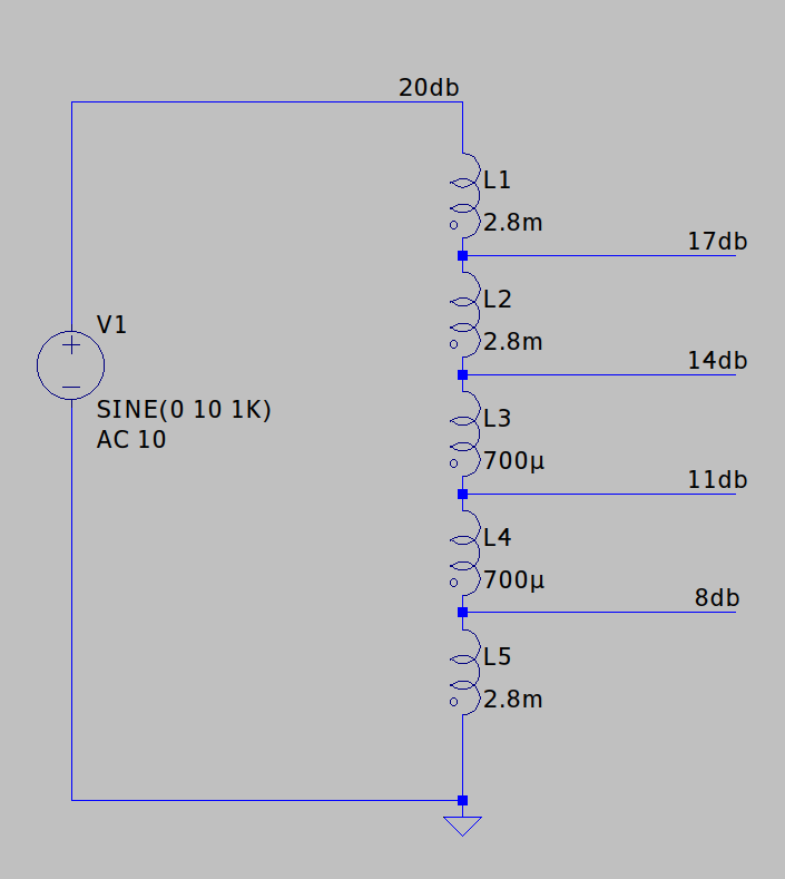
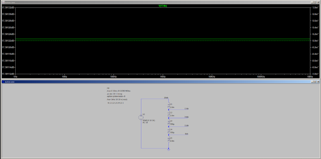
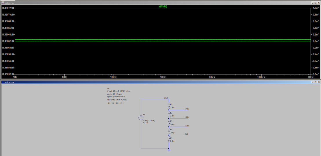
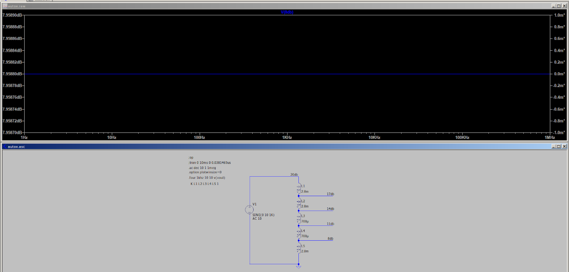
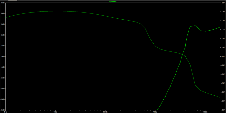
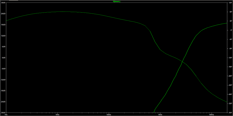
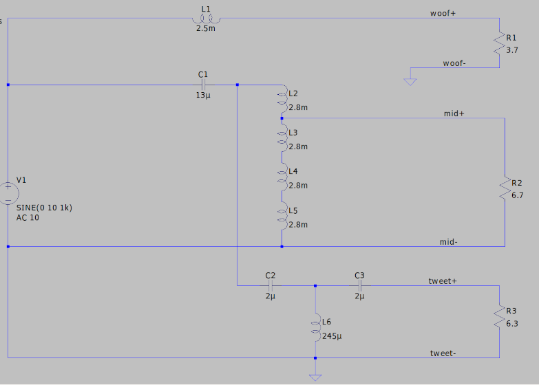
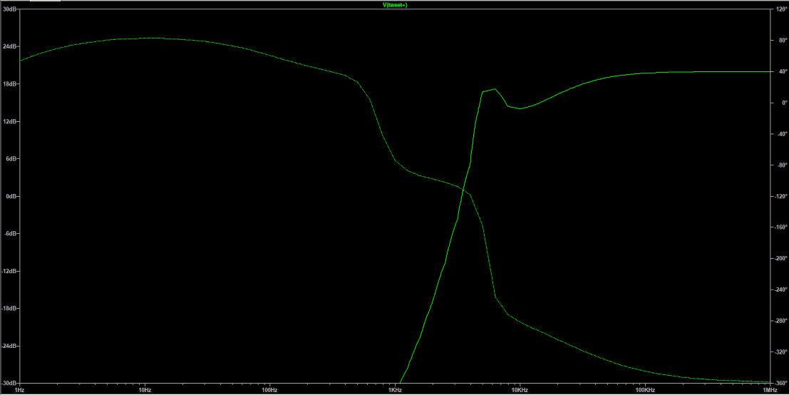
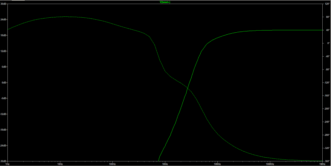
Hopefully this helps better. Input voltage is 10v (20db). We need the whole winding to be 44mH, each 4 inductors are yes 1/16 of the total inductance because of the squared function. Once you get past -6db you need to halve the next inductor (so divide by 4 again) to get just a -3db past the -6db making the -9db. That is the tricky part to make the exact model work for each tap. I left them all at 2.8mH because I got my tap I needed for the model (-3db) and the whole winding would be modeled correctly at 44mH. If I needed the next tap down would also be correct at -6db. For this to make more sense for you and everyone else I am showing the model with the other -9db and -12db inductance values for the model to work exactly how it would in real life. Starting at the top (20db), each tap going down will lower it -3db, so 17db, 14db, 11db, 8db. In the pictures, the graph is named at the top for which tap we are viewing.
-
Type AA crossover rectangular capacitor replacement
captainbeefheart replied to Tizman's topic in Technical/Restorations
The discussion about the different tweeter network values led to a simulation of the entire network which led to a question about the simulation. A little sidetracked but in my opinion a good sidetracked, some folks want a better understanding of the entire filter network and the autoformer is often misunderstood. We can steer this train back to the tweeter you watch 😜 -
Type AA crossover rectangular capacitor replacement
captainbeefheart replied to Tizman's topic in Technical/Restorations
Yes same thing different math to show it. BUT, we need the individual values of each "inductor" So the halfway tap (0-3) we have each side totaling 11mH giving a total winding inductance of 42mH. 11/4=2.75mH ^^^This would be cutting the halfway points in half again down to a value of 2.75mH each "inductor", I just used 2.8mH instead of 2.75mH because that is what the actual autoformer measures because the total winding inductance is closer to 43mH-44mH. -
Type AA crossover rectangular capacitor replacement
captainbeefheart replied to Tizman's topic in Technical/Restorations
editing- I am trying to do other work while I think of this and I am old!!! 👴 Once I finish up I will help dissect and explain the exact individual inductances and not the total inductance between each tap(1-5) to tap 0. With 10vac at input, across pins 0 and 5, you will get 10vac or 0db attenuation if you take the output from pin 5. Each tap down 4,3,2,1 are increments of -3db. We want to put into the simulator each of those individual inductance values. -
Type AA crossover rectangular capacitor replacement
captainbeefheart replied to Tizman's topic in Technical/Restorations
Let's simplify the model between inductance and turns. Let's say the total inductance of the entire winding is 44mH to make math easy If you place a center tap it would be half the turns ratio, but each side of the center tap is not 22mH like you would think, they would be 11mH because of the squared function. -
Type AA crossover rectangular capacitor replacement
captainbeefheart replied to Tizman's topic in Technical/Restorations
Basically if you want to increase by 3db it is roughly 1.41, so that is the turns ratio. The inductance/impedance ratio is a squared function or 1.98 Look at it backwards; 2.8mH * 1.98= 5.4mH 5.4mH*1.98=10.9mH 10.9mH*1.98-21.73mH 21.73mH*1.98=43mH -
Type AA crossover rectangular capacitor replacement
captainbeefheart replied to Tizman's topic in Technical/Restorations
I messed up and forgot a tap, I only have 4 inductors, I will add the fifth. It still dropped -3db but the total inductance is only 21mH in my model and with the next tap will be 42mH. -
Type AA crossover rectangular capacitor replacement
captainbeefheart replied to Tizman's topic in Technical/Restorations
The autoformer total inductance is 42mH Each tap is reduced by -3db Inductance is a squared function Inductance going from -3db onward would roughly halve looking at it from first tap to each attenuation tap; -3db= 21mH -6db=10.5mH -9db=5mH -12db=2.5mH But you don't write it in this way, each tap needs to be it's own inductance value, not the value from first tap to each individual tap like as i listed above. -
Type AA crossover rectangular capacitor replacement
captainbeefheart replied to Tizman's topic in Technical/Restorations
I have my all my directives listed away from the schematic to clean things up including the K I place the DCR in the inductance model, it just isn't seen on screen -
Type AA crossover rectangular capacitor replacement
captainbeefheart replied to Tizman's topic in Technical/Restorations
First is Tiz's values Second is stock values Third sim Changed scale up to 20kHz max
-
Type AA crossover rectangular capacitor replacement
captainbeefheart replied to Tizman's topic in Technical/Restorations
Ask and ye shall receive First image is values posted by tizman: 2.2uF/160uH/6.8uF Second is the stock values: 2uF/245uH/2uF
-
Type AA crossover rectangular capacitor replacement
captainbeefheart replied to Tizman's topic in Technical/Restorations
I have the AA network in LTSpice, I can easily show what happens by changing the values. -
Type AA crossover rectangular capacitor replacement
captainbeefheart replied to Tizman's topic in Technical/Restorations
Somehow you misquoted something Tizman said as something I said. Is there anyway to correct this. -
Bingo dead on. Amplifiers definitely need good measurements to a certain degree but there are ones not listed in the reviews or sales literature. For example reactive load instability problems giving rise to ringing or overload recovery dynamics. Measurements are taken on resistive loads while we need them to drive reactive loads. Besides performance I mentioned people like to own things that you purchase once and never have to purchase another one again, I am one. Made in America products designed for long service life and sustainability. This does not need to come at a huge price tag, there is a grossness of bling bling in the audio world and yes bias of spending huge bucks where some cheap small amp does 98% of what it does. I am a little more zen in my approach, I like hand made sustainable devices. I have salvaged so many parts I can easily make many very nice amplifiers on a beer budget. Price isn't everything, I am not attacking this because of the price, in fact I personally endorse it and say it's amazing really and perfect for the vast majority of people. Then there are weirdo's like me that just do things differently. More importantly, I have heard so many amplifiers in my life and poured over the technical objective facts along with the subjective personal experiences that I know there are minor differences between topologies that just won't show up on resistive load testing but show up in the real world with reactive loads and human beings pushing things further than they should. Yes there should always be adequate headroom, but that just isn't the case many times. Many measurements show normal operating conditions but we know someone somewhere will push it harder than they should and here are where topologies will sound way different even though the specs show the same on a resistive load under normal operating conditions; e.g. <max power. People clip from transients far more often than you care to think.
-
Totally awesome as you know this is a throwaway item once it fails on you. The repair to purchase ratio isn't worth fixing. I really enjoy American made things that will last decades, even generations. For anyone that doesn't really care about perfecting the first watt or two in regard to imaging and sound stage then these amps are just a no brainer really. I mean seriously the vast majority of the consumers want clean transparent reproduction as easy and cheaply as possible, especially with such a small footprint makes decor easy these amps just kill the competition. It's the niche market where tailoring the perfect soundscapes for your listening pleasure that may not get into these as much because let's be honest, the specs they provided aren't equal to great sound, they are a guideline but not the end all so for some ears, rooms, or speakers these units will not satisfy all. It really is the perfect amp for about 90% of the consumers.
-
After minor testing I believe you to be correct. I have been testing the 300b with positive grid bias and not happy with the results thus far. I forget who applied for the current steering patent but I am now thinking Western Electric has licensed it from them or possibly it is in public domain by now. The fact I am not running positive grid means I can actually simulate the circuit in LTSpice and have it be accurate so hang tight gang, I plan to run a simulation and we can actually see what the distortion spectra looks like with this circuit regardless of it being push pull or single ended. I don't care if it is totem pole push pull, as long as it has the same sonic signature as a single ended triode amp I am happy, and who will complain about double the power for the same tube with a little help from two transistors.
-
I have used Heyboer power transformers and they are of great quality, use them with confidence for sure.
-
Guitar amp tubes or 'hifi' tubes? (Mullard or Sovtek)
captainbeefheart replied to MeloManiac's topic in Talkin' Tubes
These questions are a can of worms but I will give it my best. The EL84M is really 6P14P Russian tube which is electrically similar to the EL84 but has higher voltage and dissipation ratings. The EL84M/6P14P is similar to the 7189 tube. I am not sure if you are talking about the current production Mullard or vintage Mullard but they are apples and oranges. If you are talking about the current production Mullard then I would hands down choose the EL84M/6P14P tube as it will last the longest in the amplifier. If you are trying to purchase vintage Mullard EL84 tubes they are very expensive and do not think you will gain any sonic improvements with that amp, so again the EL84M/6P14P is the smart choice. As for sound, you have a hifi amplifier that uses more feedback vs guitar amplifiers, also guitar amplifiers are driven into overdrive which is where the chimey high frequency comes into play with any true pentode. You will not be driving this amp into overdrive. Your amplifier is designed to meet a specification with any functioning EL84, the feedback keeps the slight tolerance differences at bay which is hallmark of good engineering. I.e. I highly doubt you will hear any sonic differences between the two types of power tubes once correctly installed and biased the same. As for the Sovtek tube that ran hotter and glowed brighter, the glowing most likely has nothing to do with anything, depends how much of the heater is showing from within the cathode, some tubes are just brighter than others unless you are talking about the plates glowing red which is bad but I doubt your situation. You cannot just swap power tubes without checking bias and making sure it is within the design parameter. The Sovtek you installed most likely were running higher bias current and needs to be biased after installation. If you cannot perform this safely I suggest you bring your amp to a tech that can properly install and bias your new set of power tubes. In short go for the Russian 6P14P-EV variant, the EL84M is a 6P14P but not the same as a 6P14P-EV, the EV is long life and more rugged, sturdier construction with slightly even higher ratings vs the 6P14P/EL84M. Or if you have the money get some really nice NOS RCA 7189 tubes and they should last a very long time, but the 6P14P-EV are damn close and will also last a very long time.