captainbeefheart
-
Posts
1422 -
Joined
-
Last visited
Content Type
Forums
Events
Gallery
Everything posted by captainbeefheart
-
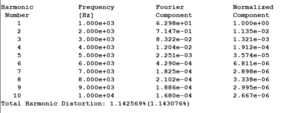
The next one is the same configuration, plain old common cathode gain stage except just one tube. I chose the high gm pentode, the 6197 because they are only $3 each and plentiful NOS around to purchase. The tube is a true pentode and wired like a triode for this application. In triode mode it is very linear. Again the triode is loaded via a CCS and needs 3v peak input to reach 70v output. There are several high gm pentodes out there dirt cheap that when triode wired make really great DHT drivers. This one has a little over 1% THD at 70v output. Not too shabby for $3

-
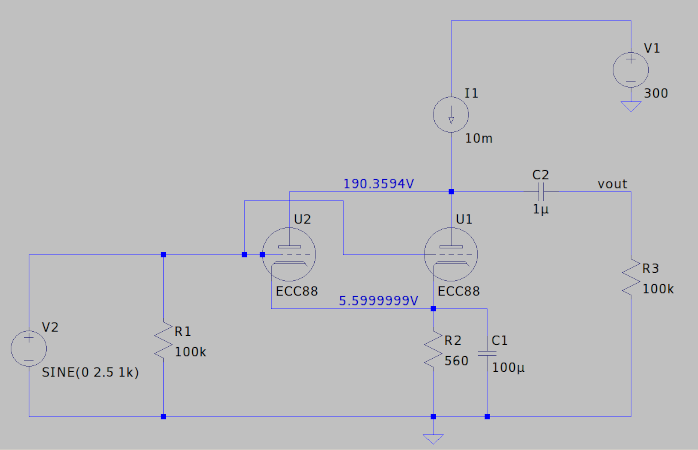
Here is one method I really like. Another single stage design where you can drive from a modern source or preamp, requires 2.5v peak input to reach 70v output. The use of one ECC88/6DJ8/6922 type tubes with both sections in parallel. Plate load is a CCS for high gain and low distortion. Remarkably there is only .6% THD at 70v output, very impressive.
-
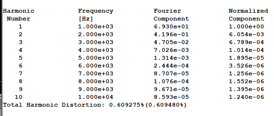
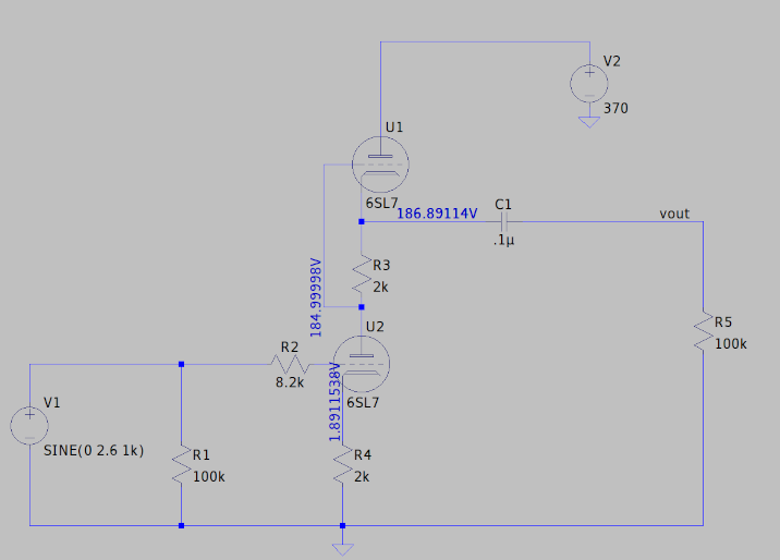
Since Curious_George made an appearance lets do his SRPP circuit next with the fantastic 6SL7. The 6SL7 is a very linear tube for being a high mu tube as shown by the low distortion. This has less gain so it takes almost 3v peak to drive to 70 volts output which is generally what I like to test for because that is the average 300b bias and hence what is needed for drive signal. This circuit although much less gain is very low distortion, it will put out 70Vpeak with just over 1% THD, impressive compared to the JC circuit indeed. The SRPP is great but suffers poor PSRR so a quiet supply is needed. The distortion does present higher harmonics. Nonetheless a good driver circuit.
-
Yes it has been around a long time which is another reason for the high popularity. I agree too much gain unless you want to add negative feedback. 200mV peak was all that was needed to drive it to 50v peak output.
-
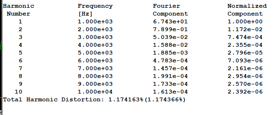
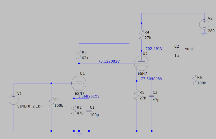
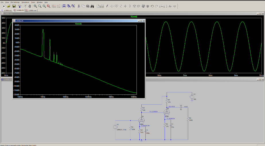
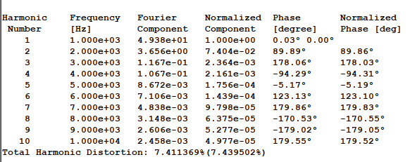
First up is a very popular design, I believe it is popular because of the high distortion, if you are listening to different amplifiers and come upon one that has a different "sound", especially with vocals, jazz, piano, etc.... this circuit will give it a warmth from the addition of the distortion of the 6SN7. The brain notices a difference in sound, a more complex harmonic fullness which sets it apart from the pack. This is good and bad depending on what you listen to and what you like, if you want accuracy this isn't the circuit for you. If you want romantic sound try this circuit. I would limit this driver to an operating point with the 300b that will only need 50-60Vpeak max to drive to full power because over 50v distortion increases to too much for my liking. At 50Vpeak we are already at 7.4% THD!!! It is predominantly second harmonic but higher harmonics are present and will continue to rise with more output.
-
Let me start off by saying Happy Thanksgiving!! 🦃 I would also like to say since joining this fantastic forum that actually has discussion sub-forums for amplifier technologies, and there are intelligent members that are into building and designing equipment I feel right at home. I was very excited to see some even using LTSpice. On to the good stuff. There was a new thread about a 300b amplifier build along with a discussion about the drivers stage. Since these DHT are so linear but require a very large voltage swing to drive to full power the majority of amplifiers you have heard you are actually hearing the driver more than the 300b. Since SET amplifiers are my absolute favorite topology I have spent a lot of time trying many different drivers. This thread is to discuss drivers and front end tubes driving your beloved SET amplifiers. I will be posting many different types of circuits and their performance, if you have a specific tube you are interested in let me know and I will put it into simulation to check the results. On to the fun!!
-
Since tubes and Mosfets are voltage controlled devices, for a given change of input voltage will have a change in current through the device, this is transconductance. So say 10mA of current change for every 1v change at input. Bipolar junction transistors are a little different, they are not controlled by a voltage but an input current and it's called Beta. So a Beta of 100 means for an input current of 1mA the device will change 100mA through it. This is how us engineers make amplifiers, we take smaller signals/currents and use active devices to enlarge them so to speak, this is called gain. All amplifiers need gain to make small signals/currents larger enough to drive a loudspeaker. All amplifiers take advantage of transconductance or Beta, the ones classified as a "transconductance" amplifiers is nothing more than just one that has a very high output impedance and behaves more like a current source compared to the vast majority of amplifiers that are a voltage source which has a very low output impedance. Schiit is just saying they try and keep the transconductance through the devices they are using as constant as possible, if you have an amp that droops in transconductance it is more or less weaker if you will.
-
I would love to help. Of course the easiest way to turn any amplifier into a transconductance amplifier is to simply place a resistor in series between your amplifier and speaker. I will look for the stock schematic, let me know exactly what you have changed so far.
-
That is different than what we are discussing, they are not saying their amps are transconductance amps. If you ever look at an active device datasheet you will notice that the transconductance is not a constant, it changes throughout different operating points, usually higher current through the device gives higher transconductance. Transconductance is good, it means it changes more current for the same input drive. In class A all devices are conducting the full 360° waveform, Class B the devices are on more than 50% of the 360° waveform but not the full 100% of it, so at one point a device goes into cut-off and shuts off with no current flow. Going back to what I said, the more current through a device the higher the transconductance is so you can see how the total current gain of the output in a Class AB amp is not steady but changing as the operating conditions of the devices change. Schiit is saying they try and keep their current gain of the output stage as stable and steady as possible even during Class of operational changes.
-
Yes the larger transmitting triodes have more of a sound to them vs the smaller DHT which are more transparent, the latter you end up hearing more of the driver than the actual power triode which is why the driver section is of utmost importance and accounts for the vast difference in sound between many of the different DHT amplifiers.
-
You won't find an official law or banning per se. In the middle ages a Monk whom I cannot remember wrote early music theory named the interval "devils music". It's use was more or less prohibited because it was believed to be the work of the devil. Composers didn't dare use it as it was considered devils music and nobody questioned the church or else. In my music theory courses the professor touched upon this briefly and I thought it was very interesting. https://www.fender.com/articles/tech-talk/the-devils-chord-the-eerie-history-of-diabolus-in-musica
-
Excellent job!! Most of us knew it had to be a bad connection to be as drastic a sound difference "sounded like headphones on the table" could not be the room EQ.
-
If dropped in the direction of cone movement there could have been a large excursion of the bass driver causing damage. Have a look at the tinsel wire running from the connection points mounted on the basket going to the voice coil, might be an easy fix.
-
Yep exactly. Really? I would say the vast majority have no idea what A2 even is but the amps that are A2 seem to get lots of praise like the Kondo Ongaku or the Shishido designs. I have tested some Class A2 amps that were driven by power tube triode plates which did not live up to the hype. I can see where if you heard one of these amps you may get a bad taste for the Class. The reason is the output impedance of the driver is not low enough to smoothly shift from A1 into A2, the abrupt transition from 100M grid impedance to 100 ohms will make for a very demanding transition from a driver. Possibly the reasoning why Western Electric is going positive grid bias so there is no large transition of grid impedance to create problems.
-
I really do not think Western Electric would add a Mosfet to pull current in opposite direction and mix up the distinction as not being push pull and call it single ended. Straight from the data sheet from Western Electric says 17 watts from one tube Class A1. They wouldn't need to resort to a hybrid push pull trick to get to 20 watts. A3 is positive grid bias
-
Yes fancy term for positive grid bias like amplifiers that use 811a type tubes. The highest power I see on the Western Electric data sheet for Class A1 operation is 17 watts with one 300b. Going with Class A2 operation you could relax the operating points a bit and still get 20 watts with one 300b. Surprised more companies aren't making higher powered 300b amps, highest I have ever seen is 15 watts from one. Now going positive grid bias on a 300b is something I absolutely have to try now. I know people will complain about parafeed but if you want to get great bandwidth from single ended it is smart to just eliminate the DC from the output transformer in order to not need a gap which absolutely drastically increases inter-winding capacitance. A long time ago when I was between jobs I would get the itch to make an amp so I used many cheapo 70v system transformers with parafeed and the results were fantastic. The headphone amp I made with parafeed was so good and inexpensive I got a lot of requests from friends to make them one.
-
Wow that would be really great!!!
-
Come again? What I meant by sophomoric is that a fuse if in a situation went past it's current rating and blew you would have no sound from the tweeters and then someone has to go in and replace the fuse, both not great situations if you want a reputation of making reliable and trouble free speakers . For an engineer the polyswitch is a much better solution as if you run past the current rating it only raises it's impedance attenuating the tweeter so you still get sound from the tweeter, then after the over current situation resolves the polyswitch returns back to it's low impedance state allowing full signal to reach the tweeters. Protection that needs no service after it's activation and also still allows sound to be heard through the driver is definitely the more elegant solution. I do not see that observation having any relation with my charisma.
-
I wouldn't fuse the tweeters, I know that is the easiest way to do it and many speakers use fuses but honestly that's very sophomoric. Order a PTC device which goes high impedance to protect the tweeter when it passes a specific amount of current, under that amount of current it remains very low impedance. Klipsch uses these in their crossovers, usually paralleled with a 220 ohm resistor. Since there is not much information up past 5kHz you do not need to worry about 50 watts going to the tweeter. For a kid I would probably set the tweeter PTC for around 2 watts maybe up to 5 watts maximum. So order a 500mA PTC for 2 watts or an 800mA PTC for 5 watts. Solder it in series with the tweeter after the crossovers filters and place a 220 ohm resistor in parallel with the PTC.
-
https://www.westernelectric.com/91e Now someone is stepping up to the plate here, Class A3 getting over 20 watts with just one 300b!!!! More companies should be getting more power from their DHT this way. Looks like they aren't letting any DC into the output transformer via parafeed with a constant current plate load, my guess is it's a gyrator load. I am curious how they are driving the grid current into the 300b. I also can't find what the gain stage front end tube is being used. What do you all think?
-
220k is a good value 👍 You don't have to worry about loading down your driver because it has a low output impedance so you could get away just fine with 100k FWIW. Some folks using the 6SL7 differently than you are would want to try and keep the 300b grid leak as high as possible but you won't have any issues with the driver arrangement you are using.
-
I just noticed you have a 390k grid leak resistor for the 300b, maximum grid circuit resistance for cathode bias is 250k and fixed bias 50k. For optimal stability 100k is a good choice as you will see in many designs. For fixed bias the good engineers start to use grid chokes for maximum stability because of their extremely low DC resistance but high AC impedance. Bonus is you also do not load down higher rp driver tubes which will give you more gain with less distortion.
-
This had me thinking. Which output transformer parasitics will create a low frequency resonance? I am fully aware of keeping the cross sectional winding capacitance low in order to keep the resonance higher in frequency, usually well past 20kHz for good transformers and up past 100kHz for great transformers. I cannot think of any C or L values that will give us a low enough frequency to boost bass? One very common thing that is misunderstood is using too low value choke and filter caps creating a resonance in the bass frequency range. For single ended amps the signal passes directly through the power supply. For example 5H choke and 47uF give a resonant frequency of 10Hz, good enough, I usually shoot for under 10Hz. The 5H and 220uF will be half that at 5Hz. I have seen many 5H or less chokes and 10uF or even lower putting a resonance right in the bass frequencies, no bueno. Any information you have on the output transformer resonance at bass frequencies would be greatly appreciated, thanks.
-
Yes of course with a normal common cathode gain stage but the driver circuit you have shown the cathode bypass capacitor will not change gain at any frequency, gain will always be, mu/2
-
The cathode impedance of the 300b is ~200ohms, with a 20uF cathode bypass capacitor your -3db frequency is 40Hz. I would increase it to at least 100uF to push the -3db point down to 7Hz that way there it is flat down to 20Hz. As for the driver stage the cathode bypass capacitor doesn't effect gain, it will increase distortion so I usually leave it out but with or without that cathode capacitor you will always end up with a gain of mu/2.