
John Warren
-
Posts
2262 -
Joined
-
Last visited
-
Days Won
1
Content Type
Forums
Events
Gallery
Everything posted by John Warren
-
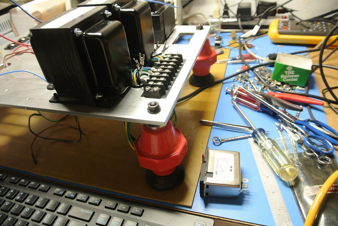
Continuing the assembly, Installed the AC power entry module. Contains fuse and the switch glows red when on.

-
A man that knows his waste treatment is always after my heart!
-
Gents- No reason to apologize. The discussion is not unamusing, for sure. And, I've derailed plenty of threads too so there you have it!
-
One can "claim" anything right? So not hard to believe. The point isn't to get wrapped around the axle, but the one making the claim is responsible for providing the substantiation.
-
First it was the two resistor thing. And now this. What's next?
-
Gents, please help me here. What is the 57 1/8" mean?
-
Knew you were joshing, glad you're finding something of interest.
-
I must of missed that part of the class...
-
There are methods described in CEA standards (Consumer Electronics Association) and amplifiers can be certified to meet those standards. If they're compliant it will be listed in the product datasheet. Audio analyzers (CLIO, NTI, Keysight, AP) are capable of measuring to the standards.
-
Clarifiers are common in waste treatment, they're settling tanks that provide some time for the solids to settle out to the bottom. The effluent is then decanted from the top.
-
huh?
-
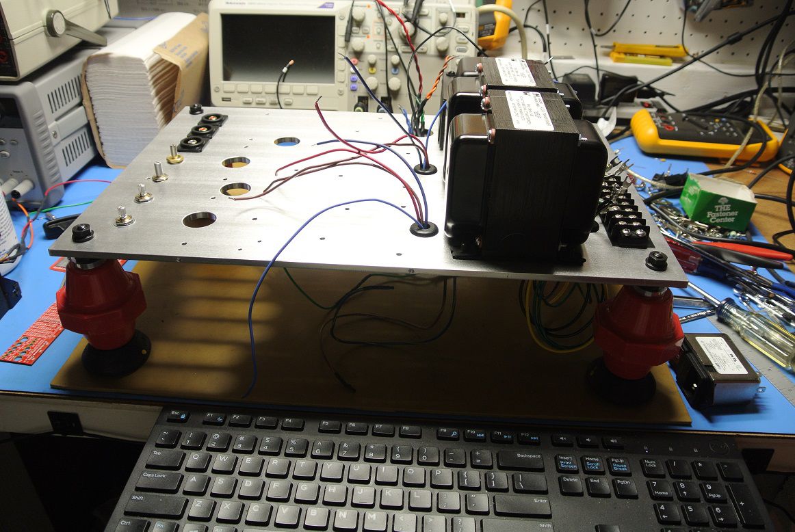
The support "legs" are high voltage standoffs used in switch gear. Not part of the amplifier design but useful during assembly.
-
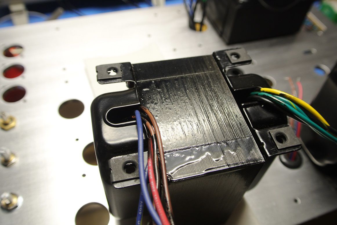
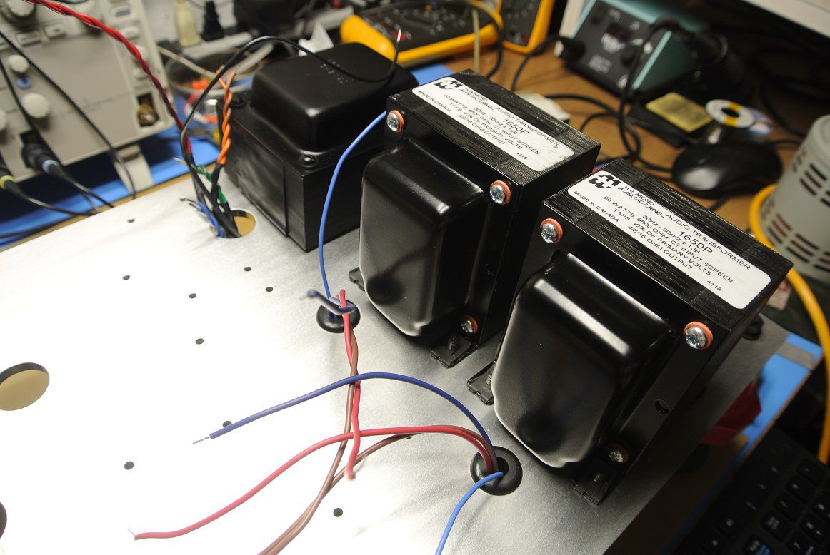
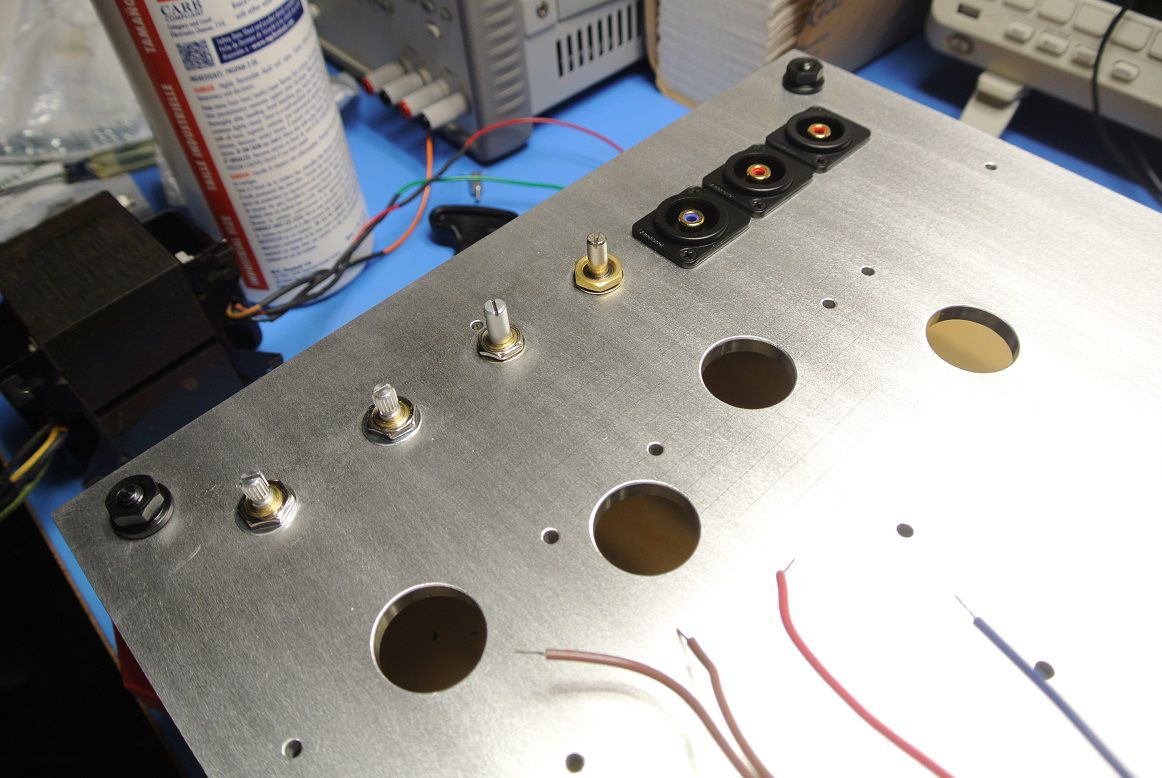
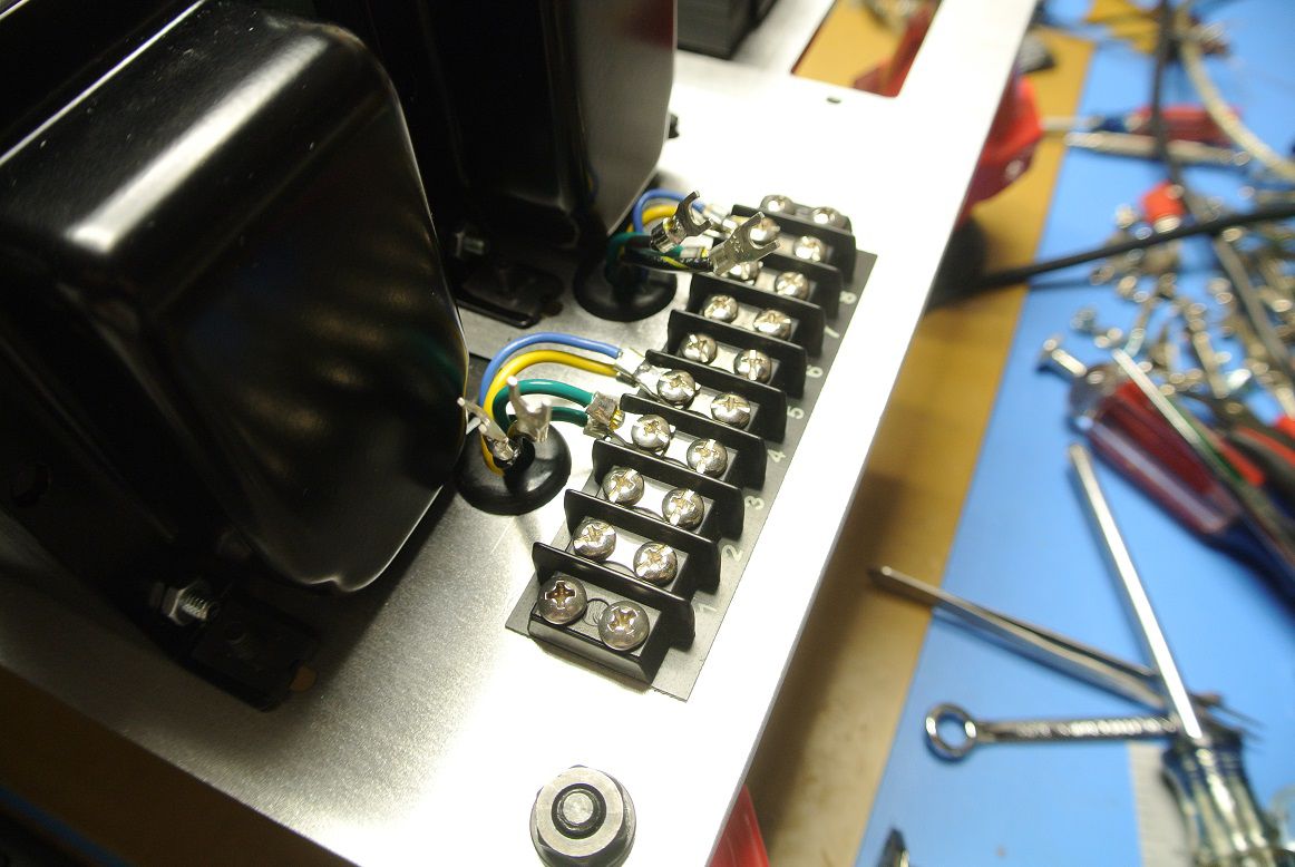
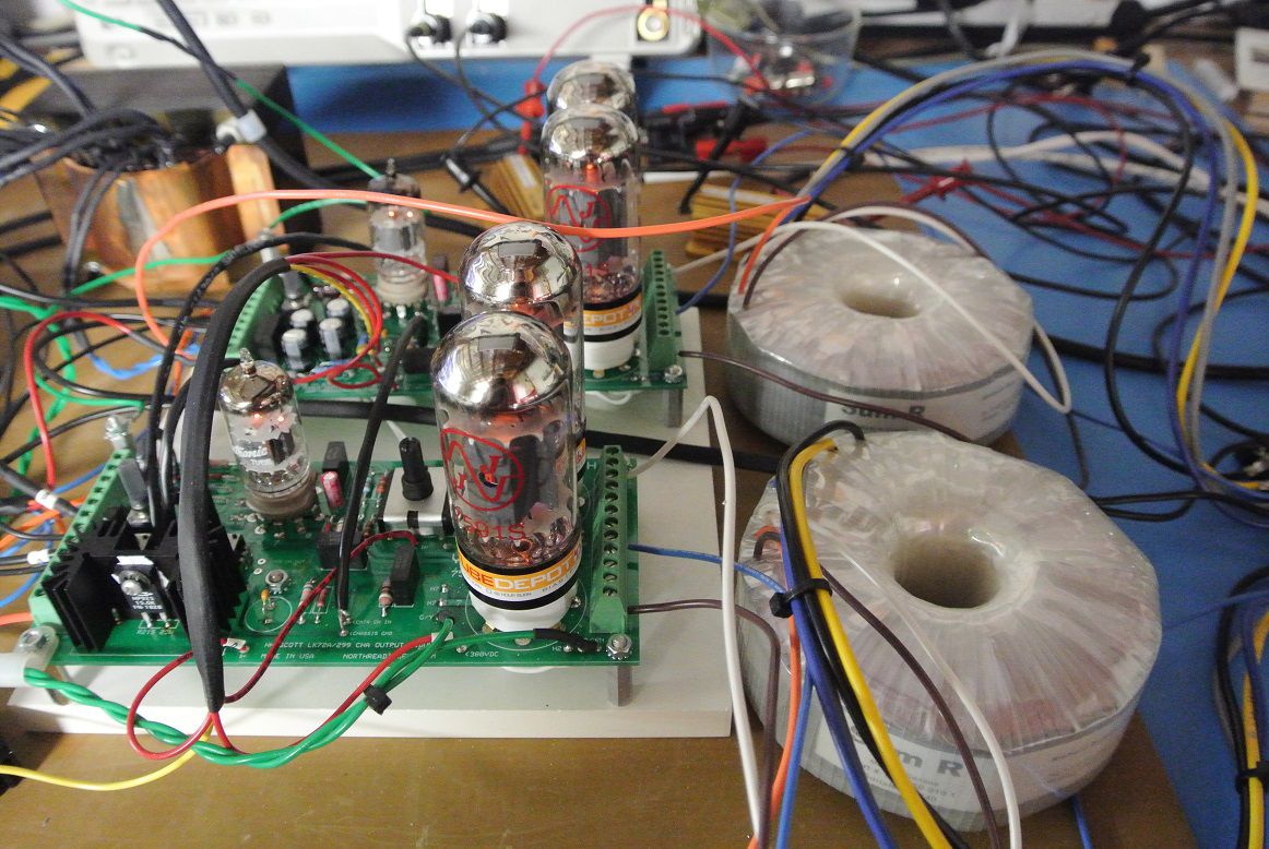
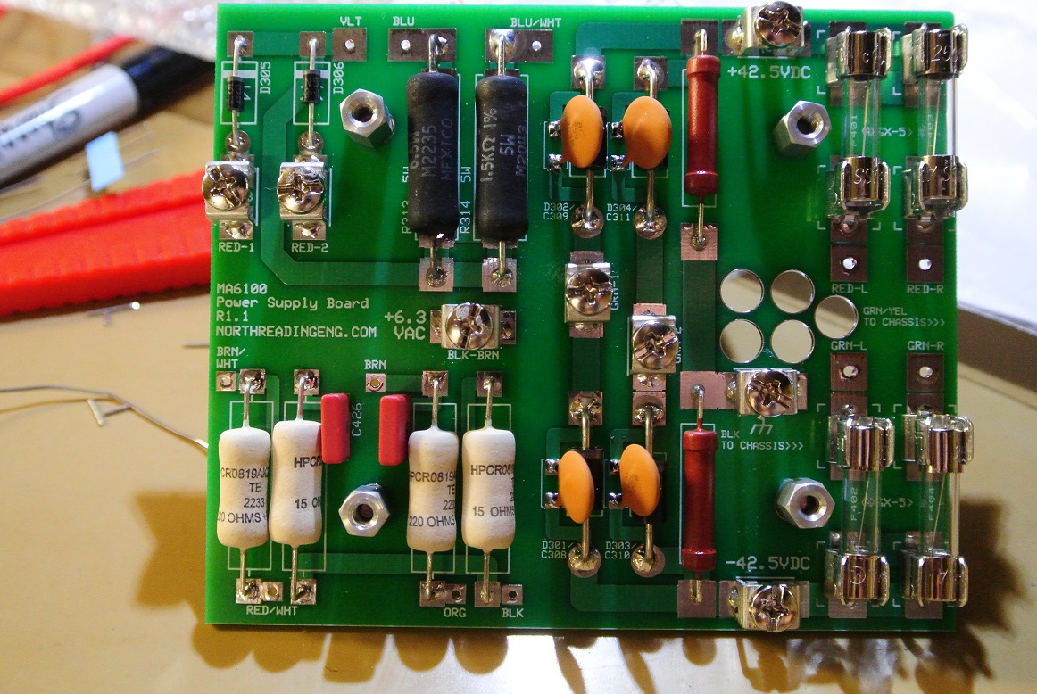
So back at it. I order 5 chassis plates from the machine shop and, due to COVID had to deal with a slip in delivery of about 6wks. First, installing transformers. Here, the Hammond OTs and the Scott LK72 power supply transformer. On the next unit, I'll be using the Heyboer LK72A replacement PS transformer and Transcendar LK72A clone OTs. In this build, it's the amp alone. Potentiometers are CHA and CHB level adjust, center channel level adjust and balance. RCA jacks are Amphenol, CHA and CHB input and center channel out are shown above the pots.
-
What did the box look like? If not punctured it wasn't the shipper.
-
Dear God man I haven't even got the prototype built and we're already "upgrading" the design. That said, there really no advantage to going Cu on this particular part but I like your spunk.
-
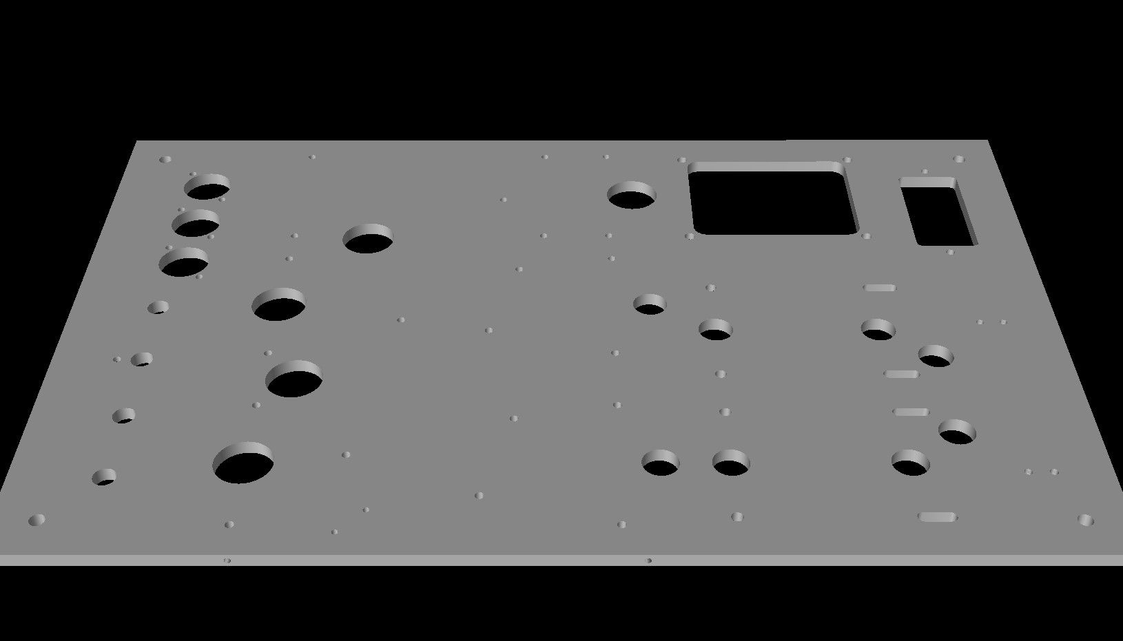
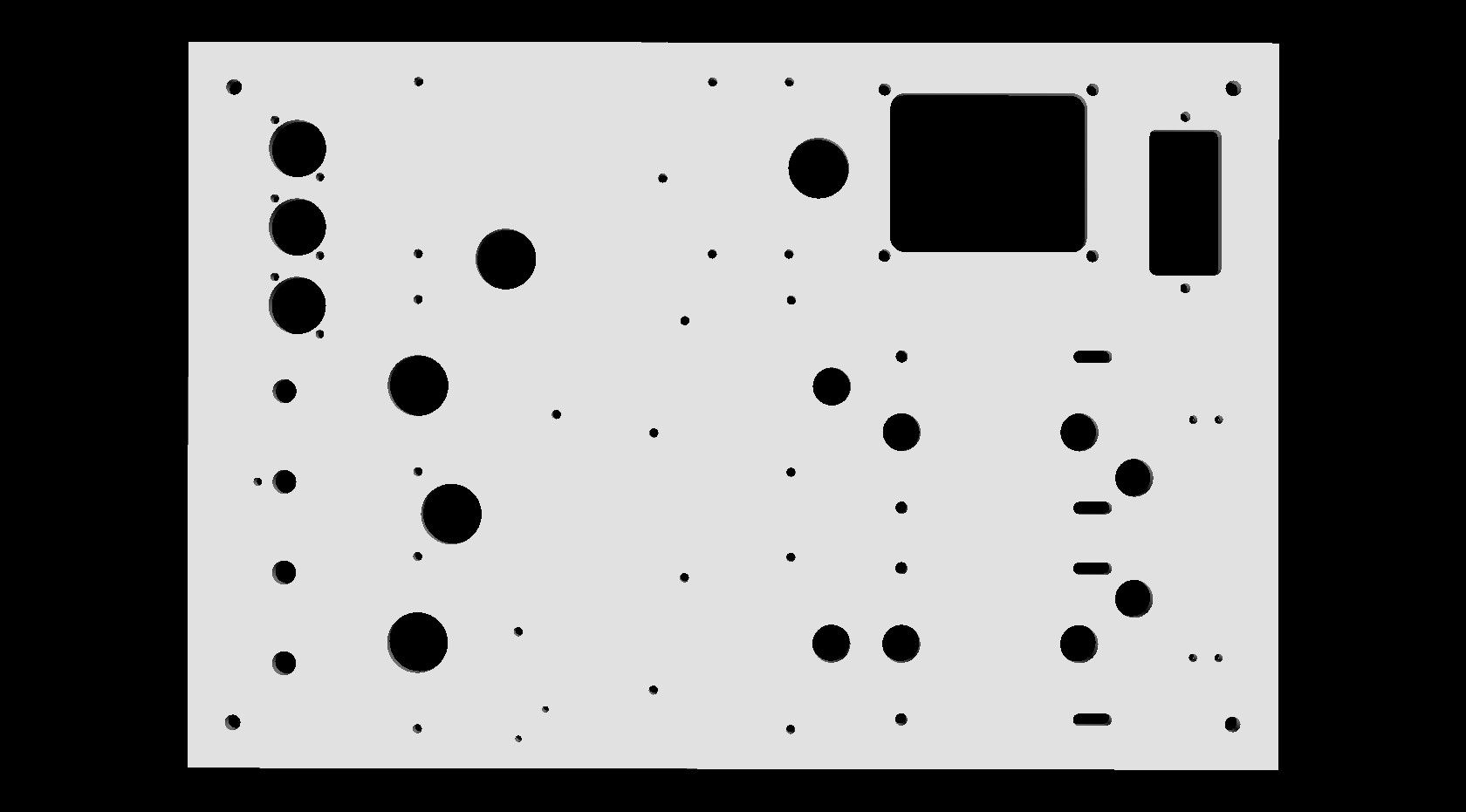
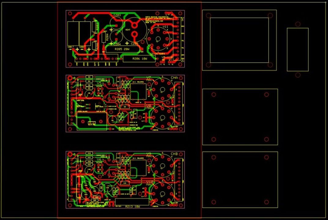
The chassis plate for the LK-72A clone and will be shipped from the machine shop in a few weeks. The plate is machined from a 1/4" plate of Aluminum alloy. PC boards and transformer locations are shown in the layout. The PC boards will be mounted to the plate using standoffs. The boards will be enclosed in a cage (red outline in the layout).
-
When you start worrying about line voltage whatever "fun" there is in this adventure, hobby or whatever you want to call this endeavor is basically lost.
-
I've been listening to the one described above for about five weeks now and I'm quite pleased with it, even with the low end tubes I'm using. I have a chassis design that is 1/4" thick Aluminum plate that everything bolts on to. I sent the plate out to get clear anodized, and will look awesome! I machined it to accept either the Hammond, Scott or the Transcendar output transfformers. Still lots of bits and pieces to attend to but it's coming along.
-
Webpage describing break-out and testing. A Wuhan Flu project of sorts. http://www.northreadingeng.com/LK-72A/LK-72A.htm
-
Some People Shouldn't Own A Soldering Iron...
John Warren replied to jlmoore3rd's topic in Technical/Restorations
Newton-meter? -
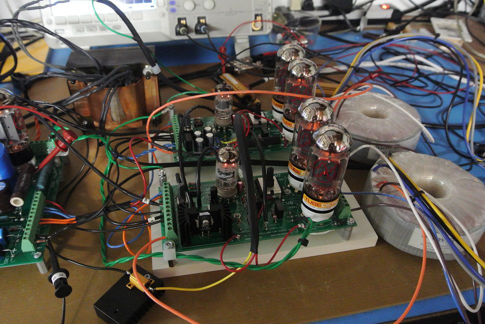
And here's the Toroidal output transformer version of the amplifier. I had the transformers wound specifically for this project. The output modules are a wee bit different (DC balance and feedback circuits) for both stable operation and enhanced bandwidth. The transformer are also sized for 60W.
-
Pandemic death grow based on the Gompertz function, it's a s-shaped (Sigmoidal) that's asymmetric about the inflection point. A simple exponential would predict millions of dead in a few months.
-
Models now show about 84,000 predicted dead from C19. About same as 2017-2018 Flue season. https://covid19.healthdata.org/projections?fbclid=IwAR1TzhAOpQza4HELTO8C6RtytagXnX3LcWXbSg9EtWjCSNxynzTsM3MdTPk
-
Fauci has stated that C19 could cause between 100-200k deaths in the USA when it's run its course. Fauci wouldn't have made estimates if he wasn't comfortable with the magnitudes. Note that the Seasonal Flu in 2017-2018 caused an estimated 61k deaths. So the C19 is 2~3X greater burden on the healthcare system than the 2017-2018 Pandemic Flu. https://www.cdc.gov/flu/about/burden/2017-2018.htm?fbclid=IwAR2DXA33LUOkiC4ad9W5_zGuzHTfysAZ8SM6U2ByGeXtGjuMDhrBVOXirO0
-
Leave it alone. Measure the Anode current of V4 and then on V5, compare. The amp should be at idle, no signal at the inputs. A close approximation of the current can be obtained by using a DVMM (FLUKE 117 for example) switched to mA DC with the common lead (BLK) clipped to the 380VDC B+ center-tap on the output transformer primary and the positive lead on PIN 7 of V4 (and then V5). The readings should be close say 2mA within each other and measured at the same B+ voltage. If they're off, say by 4mA or more then one tube is working harder than the other and push-pull symmetry lost. When the two are working in symmetry the 120Hz HV ripple in the B+ line is cancelled out (common mode rejection). Note that Anode current varies with wall voltage because B+ varies with wall voltage. There is risk of electrocution when making these measurements. The measurement raises the DVMM to the B+ potential, in your case about 380VAC. A good DVMM can perform this measurement with no issue. Do not use probes, the safe way (the only way I would do it) is using Pomona mini-grabbers or probes with extendable clips. On the meter side banna plugs that hold fast. If you short the B+ to ground you'll explode the 380V supply. Make the two connections with the amp off, set the meter to mA DC and preferable bring the amp up to 117VAC with a Variac whilst monitoring current draw and B+ voltage. The amp (or Variac) should have the proper rated fuse or one 1/2 amp lower. Then repeat for V8, V9.