Rudy81 Posted August 18, 2010 Author Share Posted August 18, 2010 Peter, good idea on something else to look at. These measurements were all taken about 1/8" from the cone center, or as close as I dare get to the cone without having it hit the mic during movement. Frankly, I'm no expert on speaker design and I don't know what considerations JC put into the design to avoid cancellation. Today I might just goof around and measure just one woofer and then two woofers at varying distances. Interesting. Edit for clarification: BTW, the woofer enclosures are totally separate, there is no acoustic connection between the inside of the cabinets. Also, my comment on the change in response above 1kHz was with a movement of an inch or two away from the center of the cone, not far enough to allow the effect of the other woofer chamber. However, I will see what results I get by diconnection one of the woofers. Quote Link to comment Share on other sites More sharing options...
Rudy81 Posted August 18, 2010 Author Share Posted August 18, 2010 Peter, BTW, here is a link to JC's original build thread where they discuss comb filtering between the woofers, which I beleive is what you are asking about. http://community.klipsch.com/forums/t/58314.aspx?PageIndex=4 Quote Link to comment Share on other sites More sharing options...
Rudy81 Posted August 18, 2010 Author Share Posted August 18, 2010 Ok, here are the results of some tests I ran to see if the dual woofer setup has any major problems with comb filtering or wave cancellation. Based on just looking at the graphs, I don't think that is any problem at all. The setup was to place the mic at mid bass bin height, right between the woofers. Distance from the woofer baffle was 3' and 6'. I tested the bin with a single woofer, both woofers, and inverted polarity as well just to see what would happen. As JC predicted, the SPL boost is right at 6dB with both woofers. When looking at these graphs, please understand that these measurements include the effects of my room in the measurements. I could spend all afternoon trying to find a good gate point to remove the room anomalies, but it is not worth the effort for this exercise. The object was to see if the dual woofer setup causes any problems. I will be uploading the REW files if anyone is interested in playing with the gate or manipulating my data. I will included the Tascam card and ECM8000 calibration files. So, here is the comparison between one and two woofers at 3' distance.The red line, of course, is the two woofer response. Quote Link to comment Share on other sites More sharing options...
Rudy81 Posted August 18, 2010 Author Share Posted August 18, 2010 In this shot, I superimposed the above results in order to get a better picture of any potential wave cancellation issues. Quote Link to comment Share on other sites More sharing options...
Rudy81 Posted August 18, 2010 Author Share Posted August 18, 2010 Here are the results at 6' for the dual vs. single woofer comparrison. The blue line is the dual woofer setup. Quote Link to comment Share on other sites More sharing options...
Rudy81 Posted August 18, 2010 Author Share Posted August 18, 2010 This is the 6' measurements superimposed. Quote Link to comment Share on other sites More sharing options...
Rudy81 Posted August 18, 2010 Author Share Posted August 18, 2010 Since Pete asked about potential wave cancellation issue with a two woofer setup, I decided to invert the polarity in one woofer and run them together. I figured this should show a huge loss in response. Here is what I got. The blue line is the original 6' dual woofer measurement. The other line is the dual woofer inverted polarity response. Quote Link to comment Share on other sites More sharing options...
Rudy81 Posted August 18, 2010 Author Share Posted August 18, 2010 Hey Rudy, it's a very busy week for me at work so I'm not ignoring you, but could you send me your measurement files so I can poke around your waterfalls a bit? Mike, I sent you an e-mail from the forum with a link to the files for download. Quote Link to comment Share on other sites More sharing options...
Rudy81 Posted August 19, 2010 Author Share Posted August 19, 2010 And now, back to the voicing of the speaker. Tonight I worked on the crossover settings since I wanted to mess around with the Le Cleach method of setting the crossover. Up 'till today, I had the crossover set at LR 48dB slope at 600Hz. It has been my starting point. I moved the setting to an 800Hz position and liked the voicing a little better. Vocals sounded a little fuller and just a bit more natural. I finally got around to setting up my laptop to hook up with the DCX so I can control the crossover from my sweet spot location. Makes it much easier to notice any changes and play with the settings while getting instant feedback. I used the Tripp-lite USB to Serial connector and it worked like a champ with Windows 7. I have had good luck with that cable. I use it to control my Russound CAV house wide controller. I am finally getting around to messing with the crossover in earnest. Quote Link to comment Share on other sites More sharing options...
DrWho Posted August 20, 2010 Share Posted August 20, 2010 Hey Rudy, it's a very busy week for me at work so I'm not ignoring you, but could you send me your measurement files so I can poke around your waterfalls a bit? Mike, I sent you an e-mail from the forum with a link to the files for download. Got them and took a quick look at work....I'm just now taking a break from work (super long day) so I'll take a closer look sometime this weekend or early next week. One quick question though, how high is the microphone in each measurement? Quote Link to comment Share on other sites More sharing options...
Rudy81 Posted August 20, 2010 Author Share Posted August 20, 2010 Dr. Who, thanks. In the 'pillow' measurements, the mic is centered on the top woofer and as close as I could get the mic withought hitting the cone. The graphs that looked at potential comb filtering or cancellation, the mic is halfway between the woofers (vertically) and 3' or 6' back. Quote Link to comment Share on other sites More sharing options...
DrWho Posted August 20, 2010 Share Posted August 20, 2010 Ya, but what is the physical dimension? Kinda hard to crunch numbers with relative measures [] I'd be interested in a response of the bottom woofer with the mic on the floor at 3' and 6'. Quote Link to comment Share on other sites More sharing options...
Rudy81 Posted August 20, 2010 Author Share Posted August 20, 2010 Mike, I had placed the mic between the drivers since the idea was to see if the drivers were interfering with each other. Quote Link to comment Share on other sites More sharing options...
Rudy81 Posted August 20, 2010 Author Share Posted August 20, 2010 The mic was placed 19" above the floor. Quote Link to comment Share on other sites More sharing options...
John Warren Posted August 22, 2010 Share Posted August 22, 2010 Rudy- Your port output is a point of discuss. I've attached your nearfield port response below. Quote Link to comment Share on other sites More sharing options...
John Warren Posted August 22, 2010 Share Posted August 22, 2010 Looking at your port response (above) it looks like the tuning frequency is between 40-60Hz. Since you have multiple ports, I do not think you can get an accurate assessment of the port characterisitcs by placing the mic in a single port. That said, the bandwidth of the port appears large, you have appreciable output two octaves above the tuning frequency (compare 200Hz to 40Hz). I like to see a sharp narrow response. Also, your measurements are taken a very low output which is good for detailed measurements (avoid turbulence). I take measurements in 3dB increments up until I either can't stand to listen to it then compare with small signal analysis for differences. Differences signify turbulence, resonance problems, etc. The impedance of the dual 2226H units I posted earlier is below. Note the minimum between the two peaks (low peak is Fl, high peak is Fh). The minimum is the port tuning frequency (it's where the woofer cone becomes almost motionless, hence the impedance is a mimimum). Quote Link to comment Share on other sites More sharing options...
John Warren Posted August 22, 2010 Share Posted August 22, 2010 The port output (red) and diaphragm only (green) from the dual JBL unit is shown below at moderate SPLs in the listening area (note these are nearfield responses). The input signal is MLS signal and the signal sent to the amplifier is cross-correlated with the mic response so the FFT knows what was sent and what was measured. Also, the nearfield measurement technique is not perfect isolation, the interactions are present and standing wave resonances exist in the vent. The peak of the amplitude response of this enclosure alignment should (and does) coincide with the impedance minimum. Quote Link to comment Share on other sites More sharing options...
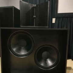
John Warren Posted August 22, 2010 Share Posted August 22, 2010 Here's where the mic was placed Quote Link to comment Share on other sites More sharing options...
John Warren Posted August 22, 2010 Share Posted August 22, 2010 For this application, the direct radiator mids cross over at 200Hz so the output of the woofer requires attenuation, hence the choke as a low-pass. About 10dB of attenuation at 400Hz was required to get a resonable response with the mids operating. Plot shows the woofer diaphragm only in nearfield (no port output) with and without a 3.90mH choke operating as a low-pass. Provides about 8dB at 400Hz. The dual units provide significant output between 40-200Hz. Quote Link to comment Share on other sites More sharing options...
Rudy81 Posted August 22, 2010 Author Share Posted August 22, 2010 John, thank you very much for your comments on the subject. First, let me say that I am rather new to all this so my ability to interpret results correctly is limited. So, please feel free to educate me and use laymen's terms when necessary. - The output was done at low levels since raising the output more causes REW to indicate I am clipping the results during the run. - My nearfield mic setup was very similar to yours. - I beleive JC's design is supposed to be tuned to around 40Hz. I can clearly see what you mean by the port response operating between 40 and 60 Hz. When I looked at both the port and the driver nearfield response, as shown below, it seemed like it covered the frequencies from 40-1500Hz. As you indicate each woofer had two ports in its cabinet and I am only measuring one. So, are you suggesting the ports are not working as they should? Do you suspect they are too big, too small, too many? As I said, intepreting the results correctly is what I need to learn. The other issue which I have noticed is that those drivers barely move, no matter how loud they run or what frequencies I play. I beleive JC made comments on that subject when he built his. Again, I don't know if this is normal or not. Quote Link to comment Share on other sites More sharing options...

Recommended Posts
Join the conversation
You can post now and register later. If you have an account, sign in now to post with your account.
Note: Your post will require moderator approval before it will be visible.