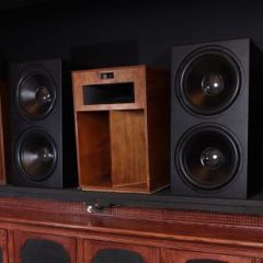
Moderators Youthman Posted April 11, 2015 Moderators Share Posted April 11, 2015 (edited) I'm wanting to do an A/B Comparison of my HK3490 with a Rotel 1070 Preamp I just picked up. I want to A/B using the same volume for both the HK and the Rotel. I was advised recently that using an SPL Meter was not an accurate method of level matching. My thought is I can get it pretty dang close but whatever... So if I wanted to use a Multimeter to level match, would I put the leads on the amp terminals or the speaker terminals and what setting should I use on my Multimeter? Below are the options I have on my meter. Edited April 11, 2015 by Youthman Quote Link to comment Share on other sites More sharing options...
Moderators Youthman Posted April 11, 2015 Author Moderators Share Posted April 11, 2015 I'm thinking I need to use the 200 V~ Quote Link to comment Share on other sites More sharing options...
pite Posted April 12, 2015 Share Posted April 12, 2015 for A to B comparison, the important thing is to measure at exact same point. When you measure at Amplifier, it'll be bit more voltage as the speaker wire reseistance is not part of the measurement. When you meassure voltage at Speaker connections, it'll be little less compared to the measurement at amplifier connections due to the voltage drop acrooss the wire. You can measure at both points which will allow you to understand the voltage drop for each speaker wire (channel). Start with 300V AC (one position right to OFF) and then change to 200V AC range if measurement is less than 200v AC for better resolution. That said, since you're not measuring Ampere, it'll not reveal the exacts that you're after. 1 Quote Link to comment Share on other sites More sharing options...
WMcD Posted April 12, 2015 Share Posted April 12, 2015 I'm quite sure that meter is not going to work for what you want to measure. It looks like it is set up for house wiring and some battery checking. It appears that the most sensitive setting for AC is 200 volts. I infer you have what is called 2 1/2 or 3 1/2 digits in the display. (The 1/2 digit is a 1.) This means it will measure up to 199 volts or 199.9 volts. So your smallest AC voltage resolution is 1 volt or 0.1 volt. You want something which will measure down to 0.001 volt AC if possible. Maybe 0.01 will do. I think you will not be so bad off with an SPL meter. You might want to give it a try before spending money. WMcD 1 Quote Link to comment Share on other sites More sharing options...
Marvel Posted April 12, 2015 Share Posted April 12, 2015 Some DDMs have a freq. feature. If not, they will be most accurate at 50-60Hz, the two standard line frequencies used in the world. Definitely use the AC setting. II have a Fluke, but not a real fancy one. The Fluke 87V has an AC bandwidth of 20Khz with low pass filter; 3db @ 1kHz. Unfortunately, it's also $350+... Bruce 1 Quote Link to comment Share on other sites More sharing options...
Moderators Youthman Posted April 12, 2015 Author Moderators Share Posted April 12, 2015 (edited) Start with 300V AC (one position right to OFF) and then change to 200V AC range if measurement is less than 200v AC for better resolution. Thanks That said, since you're not measuring Ampere, it'll not reveal the exacts that you're after. Or maybe not... I'm quite sure that meter is not going to work for what you want to measure. It looks like it is set up for house wiring and some battery checking. Yes, that's what I bought it for. So your smallest AC voltage resolution is 1 volt or 0.1 volt. You want something which will measure down to 0.001 volt AC if possible. Maybe 0.01 will do. Yes, it only measures to a 1/10th of a volt (ie 12.4). I think you will not be so bad off with an SPL meter. You might want to give it a try before spending money. That's what I tried to say in another thread where I was talking doing some A/B Testing between the HK3490's internal amps vs the HK3490 + Acurus A200. I stated that I was using a DB Meter to match the levels between the HK3490 and the HK3490 + Acurus A200. Ski Bum mentioned.... For level matching you really need to measure at the speaker terminals with a multimeter, not rely on the questionable calibration of AVR volume control settings. Slight difference in gain will be audible......Match levels by measuring across the speaker terminals while playing a CD with relevant test tones on it. Switch back and forth between the two signal paths and set gains until the levels match within 1% which is about the same as 0.1 dB. Some DDMs have a freq. feature. If not, they will be most accurate at 50-60Hz, the two standard line frequencies used in the world. Definitely use the AC setting. II have a Fluke, but not a real fancy one. The Fluke 87V has an AC bandwidth of 20Khz with low pass filter; 3db @ 1kHz. Unfortunately, it's also $350+... Bruce Bruce, about the only thing I understood there was "it's also $350". Yeah, that was over my head. I'm ok with keeping it simple. Edited April 12, 2015 by Youthman Quote Link to comment Share on other sites More sharing options...
rbtwsp Posted April 12, 2015 Share Posted April 12, 2015 Here's a dumb question, so help me understand. I always thought that amp outputs and speakers operated in DC, for example in tube systems i commonly see either diodes or specific tubes rectifying the AC to DC. I have also seen output tubes with high DC plate voltages, am I missing something or is solid state different? Thanks Bob Quote Link to comment Share on other sites More sharing options...
WMcD Posted April 12, 2015 Share Posted April 12, 2015 (edited) It is not really a dumb question. There is not much out there which explains it very, very simply. I'd suggest you find the Nelson Pass site because he has quite a few publications, at least on his solid state amps. I've explained the following before on the forum, but let's give it another go. Amplifiers do not magically enlarge the electrons. But generally we have an input signal which is music. The music is always an alternating voltage of some sort. This is because it is mimicking a guitar sting, to use and example. The string goes back and forth and the voltage goes up and down (positive and negative). The average is zero, of course. The guitar string doesn't move across the room and the voltage averages zero, too. We want to make the voltage bigger so we can drive a speaker. Enter two devices. One is a source of D.C. voltage which is high for vacuum tubes and low for solid state. This can be a battery. More often it is a combination of a source of A.C. like the wall socket, a transformer to adjust voltage. One or more rectifiers -- which direct the AC in the power supply around the right way, and also prevents the power from going back in the transformer. And a capacitor which stores or filters the stuff coming out of the rectifier pack. The result is somewhat like voltage / current out a batter. It is unchanging voltage or "direct current." The second device is a valve. The Brits call a vacuum tube a valve and transistors of all types are also valves. They all have a handle where our music signal is attached. The music works the handle on the valve to turn it off and 1% on or 2% on or 3% on, etc. so you can get all levels of "on" or conductance. The source of D.C. voltage / current is like water pressure fed to the valve. So what comes out of the faucet is controlled by how you twist the valve handle with the music. "Ha" you say. But how can this work, if the valve only makes the current flow more and less. The music and guitar string are reversing direction. The valve analogy only works in one direction. Yes, this is an inherent limitation on or valve and it is no reason that things get complicated. But there are ways around that. Let KISS for now. WMcD Addition by Edit. Of course the speaker or amp output is the flow of the water though the valve and into the tub. The analogy shows that we are not really listening to a magically magnified, amplified signal. Rather, we are listening to the effect of the input signal twisting the handle on the valve (a grid on the vacuum or a base or a gate on a transistor) and letting current from the power supply though. One issue which comes up is: Exactly how accurate is this valve thing? Does the flow through "exactly" change the current, according to the twist on the handle. No, it doesn't, for various reasons. Edited April 12, 2015 by William F. Gil McDermott Quote Link to comment Share on other sites More sharing options...
pite Posted April 12, 2015 Share Posted April 12, 2015 (edited) Hmmm... Interesting analogy of guitar strings and AC voltage/current... We used a tidal wave Audio or music signals can be called either AC Voltage or DC Biased voltage. But when said AC voltage most people would relate it to home AC voltage with a frequency of 50Hz or 60Hz depending upon the country. In case of audio it's varying signal between 1Hz to 25kHz (or more) for different instruments, female/male vocals, ambient/surround sound, etc. and then voltage & current level for the loudness aspect. Hence for long, we've be saying audio signal instead of AC or DC biased signal. Returning to Youthman's measurement quest, modern AVR or amplifier use logarithmic potentiometer (equation) as it's better than linear control for the volume control. Thus, it's bit difficult to draw a straight line and come up with a number. e.g. let's say one amplifier can provide 100w rms for a range of 0-100% while other can provide 150w rms, then in that case depending up on the implementation 50% on 1st amplifier (100w rms) might NOT be exactly 50w rms and similarly 75w rms for 2nd amplifier. In contrast, if it was linear volume control then one can set 50% on 1st amplifier to provide 50w rms and then the volume dial could be set at 33% to provide 50w rms on 2nd amplifier. Thus for correct A to B comparison, due to logarithmic volume control, one need to measure output of the amplifier instead of SPL. In other words, if 2nd amplifier is set to 50% then there's a good possibility of hearing a higher SPL because the amplifier output will be more than 50w rms due to logarithmic volume control. This will falsely imply that 2nd amplifie is louder and probably clear (because being loud). Edited April 13, 2015 by pite Quote Link to comment Share on other sites More sharing options...
WMcD Posted April 12, 2015 Share Posted April 12, 2015 (edited) Let me backtrack a bit on the SPL meter and say . . . maybe it is not the best. If I understand: You want to make an A:B subjective (hearing) comparison on two pre-amps. You've been told, quite correctly, that in A:B tests you should match the output of the equipment as closely as possible. This is because even a little more output will sound better. We don't know how you're going to do the A:B switch over. Maybe you can tell us. Please note here that you don't have to measure frequency with the meter. So don't worry about having a freq counter function. You do want to measure AC level, someplace. It is true that meters are not always "flat" across frequencies. That doesn't matter either because you're just going to match at one freq in the set up situation -- which is what we're talking about. What you do need is a source of a sine wave. Most CD test recordings will have a 1000 cycle tone. Or you can find something on the Internet. So, in your calibration session, you want to feed that to the two preamps and adjust output of each with the respective volume controls until they are equal. The question is, though, where to measure. I believe the best place to measure is at the output of the power amp. This does away with issues of loading down the output of the pre-amp. Now, let me give you some examples from my experience with testing speakers. As you may know, the assumption is that if we feed a speaker with 2.828 volts, the speaker resistance is assumed to be 8 ohms and the electrical power delivered into the 8 ohm speaker is 1 watt. This is because Power = Volts x Volts / Resistance. Therefore volts x volts must be 8. This way the division by 8 results in 1 watt. To make this work, the volt magnitude must be 2.282 volts. That is square root of 8. 'Cause 2.828 x 2.828 = 8. But. When you set things up with the 1000 hz tone, and turn up the volume so there is 2.828 volts delivered to the speaker, it is going to be very loud. 104 dB for the Klipsch horn types. If you have an SPL meter located 1 meter away it will measure about 104 dB. This is incredibly dang loud. So we turn the gain down. But to what? As a guideline. Suppose we want to put 0.1 watt into this theoretical 8 ohm load? We must put in a voltage at a level of square root of 0.8. That is about 0.894 volts. Now the acoustic output is 10 dB down from the 1 watt level. This can still be pretty loud. Suppose we want to put in 0.01 watt? We must put in a voltage of 0.282 volts. The acoustic output is 20 dB down from the 1 watt level. It is tolerably loud. But, we rally don't care too much because we just want to adjust the volume controls to get this voltage equal. The 0.282 is nice to have as a guideline. If you want to use 0.300 volts, fine. Or 0.200 or 0.100 This shows why you need a volt meter which will read down to about 0.001 volt. It is nice to get that third (least significant digit) equal. In practice with a digital meter, that can be difficult. Just a little bit of twist to the volume control will bounce it. But see what you can do. BTW, if you wish to check these calculations, you can use the calculator which comes with Windows in Accessories. Set it to Scientific. WMcD Edited April 12, 2015 by William F. Gil McDermott 1 Quote Link to comment Share on other sites More sharing options...

Recommended Posts
Join the conversation
You can post now and register later. If you have an account, sign in now to post with your account.
Note: Your post will require moderator approval before it will be visible.