khorn58 Posted October 8, 2003 Share Posted October 8, 2003 That 15 speaker sure looks a lot like a RCF dual voice coil speaker. New in the 80's I think they sold for over 200 or 300 each. EAW used them in the top of the line horn loaded Pa cabnets . If they are RCF's they are great speaker I have 2 in some cornwall clone cabnets and they are nice sounding not muddy at all. They would make killer speakes for pro lascala botoms if they are RCF. I will go look at mine later this week and get back. Quote Link to comment Share on other sites More sharing options...
John Warren Posted October 10, 2003 Share Posted October 10, 2003 , Quote Link to comment Share on other sites More sharing options...
Rockets Posted October 10, 2003 Share Posted October 10, 2003 John, when dealing with eBay you can never be sure of anything! Here's what I bought. http://cgi.ebay.com/ws/eBayISAPI.dll?ViewItem&item=3052020217&category=50597 Hopefully they're legit. I'd rather had a matching pair, but used, and $20 over the price of new for two, plus free shipping I don't feel too bad about the deal. Especially after seeing someone else earlier paying $305 for a used pair! (What were they thinking???) Of course, I don't have them yet to inspect them either... I've got a quick question on something that's bugging me. The Lascala base is cut off at 400 hz correct? The K-33 is 4 ohms? Then why/how in the hell does Klipsch get away with using a 4 mh coil in the AL (I think) and a 2.5 mh in the AA crossovers? From what I can tell a 1.59 mh should be used for a 4ohm load @ 400 hz. I'm exposing my ignorance, but in this case I'm happy to do so! Khorn58, I'd still be interested to hear what you find out. Thanks Quote Link to comment Share on other sites More sharing options...
Q-Man Posted October 10, 2003 Author Share Posted October 10, 2003 John will correct me if I'm wrong, but since the 4 ohm driver is being horn loaded that changes the impedance. The network now sees it as being more like a 6 to 8 ohm driver. Quote Link to comment Share on other sites More sharing options...
John Warren Posted October 10, 2003 Share Posted October 10, 2003 Q-The plot below is a 4 Ohm nominal impedance driver in the Klipschorn (not the K33E). As you can see, attempting to ascribe a nominal impedance to this chart is close to impossible (the woofer is in series with an inductor). The DC resistance of the coil was 2.3 Ohms. Note that the impedance is a minimum of 4 Ohms. Quote Link to comment Share on other sites More sharing options...
John Warren Posted October 12, 2003 Share Posted October 12, 2003 Here is a K33E both unbaffled and in the folded unit. The impedance is certainly higher above 100Hz but not so below. I used a calibrated voltage divider setup that reads a 10 Ohm non-inductive resistor to with about 2% of the its actual value from 5Hz to 200kHz. Frequency was measured using a precision counter. Fs is about 27Hz, horn cutoff is about 35Hz. So to answer your question, the answer is "yes" the network sees a higher impedance because the only part of the network that sees the higher impedance is the woofer inductor, and, at the frequencies the inductor is active, the impedance of the system is higher than that of the driver operating in free space. Quote Link to comment Share on other sites More sharing options...
Rockets Posted October 12, 2003 Share Posted October 12, 2003 Q-man and John, I appreciate your time and effort on this. The question still out there is WHY does Klipsch use different values in their crossovers for virtually the same application? I haven't looked at all the different schematics for each generation of crossover, but what I've seen so far is no two are alike concerning the 400hz bass. John, you have shown how the impedence changes and what it measures at a given frequency. I would agree that this should dictate the value of the inductor when designing for a certain frequency cutoff. I can see where this would factor in on part of my question. What I don't understand is why Klipsch, armed with this data, would use different inductor values for the same application. The magnitude of difference between the AA at 2.5mH and AL at 4.0 is significant (at least to me). See where I'm coming from?? Thanks TC Quote Link to comment Share on other sites More sharing options...
John Warren Posted October 12, 2003 Share Posted October 12, 2003 ---------------- On 10/12/2003 5:27:14 PM Rockets wrote: you have shown how the impedence changes and what it measures at a given frequency. I would agree that this should dictate the value of the inductor when designing for a certain frequency cutoff. >>The plot was to address the issues regarding alternatives for the K33E. If I was "screening" for a replacement I would look for an impedance response similar to the unbaffled response shown above. With a nive low Fs (like the K33E), the horn cut-off of 35Hz will be realized. With the K33E rated at a 4 Ohm nominal impedance we also get an idea of how the impedance increases when horn loaded. The impedance isn't the only consideration but it is a good place to start. I will plot the results of others. I can see where this would factor in on part of my question. What I don't understand is why Klipsch, armed with this data, would use different inductor values for the same application. The magnitude of difference between the AA at 2.5mH and AL at 4.0 is significant (at least to me). See where I'm coming from?? >>Same application? The AA is a first order low-pass. The AL is second order. ---------------- Quote Link to comment Share on other sites More sharing options...
Rockets Posted October 13, 2003 Share Posted October 13, 2003 John, I can see what we have here is a failure to communicate! My inquisition was less seeking a K-33 alternative, but more trying to understand why Klipsch uses inductors of different values, all seemingly aimed to a 400hz cutoff, using the K-33 in the same folded horns. As far as application, I was referring to the use in the Khorn and Lascala. Maybe you answered my question by stating one was a first order, while the other was a 2nd. I need to do a little more research... There is much I don't understand about all of this, hence my questions. I appreciate your help and patience. Thanks again. Quote Link to comment Share on other sites More sharing options...
John Warren Posted October 13, 2003 Share Posted October 13, 2003 ---------------- On 10/13/2003 5:30:03 AM Rockets wrote: As far as application, I was referring to the use in the Khorn and Lascala. ---------------- And hence different crossover topologies. The LaScala and Klipschorn are bass horns with different roll-off and impedance responses. The attenuation response (the order) of the lo-pass section AND the response of the mid-range horn relative to this behavior are taken into consideration when the network topology is selected. The AL-type network is (to my understanding) limited to the LaScala. Quote Link to comment Share on other sites More sharing options...
Rockets Posted October 13, 2003 Share Posted October 13, 2003 Thanks John. I may have misread or understood about the use of some of these crossovers. I 'thought' they were universal, in that they were commonly used in both the Khorn and Lascala. Appreciate the help. I guess I'm not as crazy as I thought...there's a long thread on here "types AA and AL compared" started by Erik Mandaville using both in his Lascala's. From reading it I gather the real battle is between the AA's (modified) and the ALK's.... Quote Link to comment Share on other sites More sharing options...
Rockets Posted October 13, 2003 Share Posted October 13, 2003 I CAN'T believe this...I just got a single Lascala as a "buy it now" on eBay for $275...AND it's LOCAL so I can go pick it up. There has to be something wrong with it.... http://cgi.ebay.com/ws/eBayISAPI.dll?ViewItem&item=3053178838&category=14993&rd=1 Quote Link to comment Share on other sites More sharing options...
lorcoll Posted January 16, 2004 Share Posted January 16, 2004 I would return to speak about the sound of the 290/311 combo with a stock Klipsch network or ALK. I think many people would upgrade their Khorn or other Heritage model and I'm confused for the best choice: Al prefers 511(811) with K-55, Q-man prefers 290/311 combo, etc... I have recently bought the Altec 511B for my Khorns and I don't know if it is superior to K-400 on all spectrum: I think I lose something, the voices are good but not like the k-400 in a lot of cases and I hear more boom than the k-400. But I cannot say that 511 is worse respect the k-400. Can others contribute to say what mod is objectively (and not only the personal taste) better for mids in the Khorns or La Scala? In theory the combo 311/290 can be the best but it's a good mod if it isn't necessary to do a hard modify in the network. Thanks and excuse me for my english (it's difficult translate all my thought). Quote Link to comment Share on other sites More sharing options...
Al Klappenberger Posted January 16, 2004 Share Posted January 16, 2004 Guys, WOW! It looks like all my inputs have managed to create enough confusion to frustrate the entire Klipsch community! I guess maybe I should keep my yap shut! Nah.. Here I go again: I think most of the problems with all of this is that you sometimes can't just pull out one horn and stick in another one without some kind of network change unless you keep the same driver. My advise to several people has been to replace the K400 horn with the Altec 511. The rub is that the K400 really goes lower than the Altec 511 and the K55 driver doesn't really fit. When you start fooling with the 311 horn things really get weird! Personally, though I have not heard that horn, I think it makes a lot of sense for the Khorn if you can cross it over lower. Now the network design really becomes a problem! The bottom line is really that making a complete loudspeaker is a bit more complicated that just swapping parts around. That's why Klipsch has invested so much money in anechoic chambers and analysis equipment! It's kind-of like putting a Chevy V8 engine in VW beetle. The unforseen problems will literally kill you! Al K. Quote Link to comment Share on other sites More sharing options...
Q-Man Posted January 16, 2004 Author Share Posted January 16, 2004 I have to agree with Al. I began swapping drivers and horns over a year ago. My goal was to find a driver and horn that sounded better then the K-55 and K-400. A horn and driver that I could tell everyone to buy and swap out and still be able to use a stock Klipsch or the ALK network with it. I thought that the ALK network was the answer, because one can attenuate the mid driver. Unfortunately this didn't work eather. Even thought I tried some different 16 Ohm drivers with about the same sensitivity as the k-55 these networks didn't cross over at 400 Hz any longer. The drivers had different impedance values at different frequencies and dictated where the crossover point would be and at what impedance. The ALK network was just good enought to allow me to narrow down my driver choices. Once I found the driver that I felt sounded way better then the K-55 and better then the others it was time to fine tune the network. As you know I prefer the 290. The ALK and John Warrens AA wouldn't let the 300Hz driver crossover below 550Hz. I added a 3UF cap to the AA to lower the crossover point to about 400Hz. Better, but it still needed more. This in when I sent John a 290 driver and a 311 horn. John found out a few more things about the driver and also that the horn had a nasty 800Hz peak. He took care of this peak with a notch filter in the new network. Maybe I can get him chime in and discribe what he did. I'll post a picture of the four networks that he built. I hope to get them in the Klipschorns and try them out this Sunday. None of this is as simple as I first hoped. The easiest thing to do is to use the Cobreflex horn, since the K-55 can just screw onto the back of it. It does a better job then the 511, maybe because it's a 200Hz horn instead od a 500hz horn. But, its a curved horn like the 311 and means building a new top end for the Klipschorn. You can't have your cake and eat it too. Once I get everything perfected, I may be able to offer this mod or one similar to it as an upgrade to Klipschorn owners. Quote Link to comment Share on other sites More sharing options...
Q-Man Posted January 16, 2004 Author Share Posted January 16, 2004 Here is a picture of the four networks that John built for me after having the 290 and 311 on his test bench for about two months. He also gave a listen to this driver and horn with the JBL 2404H tweeter on top of one of his Klipschorns. I think that he was quite surprised. Quote Link to comment Share on other sites More sharing options...
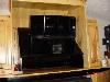
Q-Man Posted January 16, 2004 Author Share Posted January 16, 2004 Here is a picture of one of the new tops on the Klipschorn. It's hard to see, but the JBL 2404H tweeter is below the 311/90 horn. These are still prototypes, so don't poke too much funat me. Wait untill I show you my center channel Klipschorn above th RPTV. Quote Link to comment Share on other sites More sharing options...
Q-Man Posted January 16, 2004 Author Share Posted January 16, 2004 Top with tweeter below. Quote Link to comment Share on other sites More sharing options...
Al Klappenberger Posted January 16, 2004 Share Posted January 16, 2004 Q-man, There is one possibility that you haven't tried.. It's the extreme-slope type network that I have been investigating lately. I would enjoy building one to cross the Khorn to the 311 at 300 Hz. It would solve the problem of power below the 300 Hz cutoff causing damage to the driver and allow the 311 to work down to where it can really help the Khorn where it starts to poop out. Think about. I would be willing to do it for the cost of the parts alone. You would actually need two. One at 300 and another one to seperate the 311 from the tweeter. The 300 Hx unit would also be very large. You could never get it inside the speaker. You might even need to build a false front that would conciel it between the Khorn front and a board in the same plane with the tweeter. It might actually look good if done right. I'm sure you could do that with your woodworking skills. Al K. Quote Link to comment Share on other sites More sharing options...
Al Klappenberger Posted January 17, 2004 Share Posted January 17, 2004 Q-man, Well... I did it anyway! Doing a computer design for a filter only takes a few minutes. It's laying it out and building it that takes the time. Anyhow, here's the design for a 300 Hz extreme-slope crossover for a Khorn. The parts values are not as bad as I thought they would be. The capacitors in the lowpass section could be mylar rather then polypropylene. All the inductors would be of #14 solid wire. The 5.1 and 6.8 mHy inductors will pretty much determine the size of the network. Note that the 1 mHy of the K33 woofer driver is actually part of the filter. This will present a very flat resistive 6 Ohms load to the amp. I think this would really help a Khorn using a 311 Altec horn. Crossing at 300 Hz will increase the overall efficiency of the speaker by actually utilizing the natural peek of the Khorn woofer at that frequency. The network kills everything below 265 Hz by at least 25 dB. That should allow the squawker driver to safely handle a lot of power. Think about it! Al K. Quote Link to comment Share on other sites More sharing options...

Recommended Posts
Join the conversation
You can post now and register later. If you have an account, sign in now to post with your account.
Note: Your post will require moderator approval before it will be visible.