Greg Oshiro
-
Posts
116 -
Joined
-
Last visited
Content Type
Forums
Events
Gallery
Everything posted by Greg Oshiro
-
All-- This started out as a reply to Pete H in the most excellent Cinema F-20 build thread (http://community.klipsch.com/forums/t/159382.aspx). The reply got rather long-winded, so rather than hijack that thread, I'm starting a new post. I'm fairly new here, so I don't know about any beginner's guide to measurements that might exist. This is likely not a Crayola explanation, but maybe it will help. The measurment work I've done has been in large rooms or outdoors. Measuring subwoofers in domestic listening spaces (acoustically "small" since the wavelengths of the LF sounds are comparable to the dimensions of the room) is problematic in that the room and the SW interact. I'm not certain if there is a method that can characterize a SW from measurements made in a "small" room . That said, what is usually used to characterize a speaker is its "transfer function" (TF), which is basically the ratio of sound out to voltage in, and is a frequency domain data presentation. The TF is the engineering complete version of what is usually called the "frequency response". The TF has two parts, the magnitude and the phase. Historically (sp?), it was difficult to measure the phase, so it wasn't done. The magnitude is usually presented on a graph of dB (proportional to the logarithm of the magnitude) vs. frequency on a logarithmic scale. Since about 1980, various low-cost methods of measuring the complete TF have become available: TEF, MLSSA, Clio, and a bunch more. One of these is REW, which is as low-cost as it gets. I'm a TEF guy and I havent had a chance to learn REW yet, so I hope some REW-fluent folk can chip in here. The REW V5 help document has a section titled "Impulse Responses" which will help you make impulse response (IR) measurements. It turns out that the IR and TF are mathematically related by a thing called the Fourier Transform, so if we know one, the other can be calculated, with some caveats, however. When measuring impulse responses in an environment with reflections, it is usually desired to not include the relections in the measurement, so the measurement tells us the TF of the direct sound only. Read Floyd Toole's book for an explanation of why we are interested in the "direct sound only". The REW help doc has a very good explanation of how the direct sound is culled from everything else. What is done is called "windowing", where we only use the portion of the impulse response from the time of the first arrival of sound to the measurement mic to a time just before the first reflection arrives at the mic. One of the consequences of windowing is the loss of frequency resolution in the measurement. We have to use some numbers here to help explain: A 100 Hz pure tone (sine wave) has a period (T= 1/frequency) of 10 milliseconds (mS). That means our window has to be at least 10 mS wide to accurately measure the amplitude at 100 Hz. It's actually worse than that, because of the consequences of the shape of the window. It also means that our data has a "frequency resolution" (FR) of 100 Hz. This is kind of like the 100 Hz data point being an average of everything from 50 Hz to 150 Hz. That's about 1-2/3 octaves. Not a very meaningful measurement. In order for the data to have an FR of 1/3-octave, we need to look at the ~470 Hz data point or higher. So let's go back to an IR measurement made in a small room. If the time between the first arrival and the first reflection is 20 mS (a wall about 10 feet behind the listening position and *no* side, floor, or ceiling reflections), we get FR= 50 Hz, so we get 1/3-octave resolution at 235 Hz, and better above that frequency. Now back to the SW measurement difficulties. for FR=20 Hz, we need a window that's 50 mS wide. That means the first reflection has to arrive more than 50 mS after the direct sound, but still that means 1/3-octave resolution at 94 Hz. Hardly subwoofer-land. In 50 mS, the sound will travel about 50 ft. In that 50 mS, the sound will go past the measurement mic and bounce off a few surfaces and go through the measurement mic position a few times and corrupt the measurement. for 1/3-octave resolution at 20 Hz, we need FR=~5 Hz. That's a time window of 200 mS. Many reflections will be included in the measurement. Now there may be a way around this for corner-placed speakers. This is a theory I have that has not been vetted, so I hope a real acoustician will chime in. The pressure response of a sound source in a corner can be measured if the mic to speaker distance is within 1/4-wavelength of the highest frequency of interest *and* the mic position is symmetric in all 3 planes. So, on a floor that is acoustically reflective at the frequencies of interest, centered on the speaker, as close to the speaker as possible. Note that this probably won't be possible on vented speakers, since this is a near-field measurement and the output from the vent and driver are significantly different. I think it will work for sealed enclosures and horns (which is all we really care about ). Carpeted floors will be as reflective as the structural floor at 20 Hz, but a joist-supported floor may not be so reflective. One of the few times I like slab-on-grade construction. Any reflection with an amplitude >20 dB below the first arrival will not significantly corrupt the measurement. That 20 dB difference corresponds to a (direct source-to-mic distance)/(source-to-mic via reflection distance) of 10 to 1. If the mic is on the floor at the center of a Khorn, it's 14 inches from each horn mouth, so any sound path from the horn mouths to the mic via reflections that is greater than 140 inches (~12 feet) will be at least 20 dB below the first arrival. Other speakers with a single output will allow a smaller speaker-to-mic distance and better rejection of reflected sound. 14 inches is 1/4-wavelength at about 240 Hz, so we can get data that's good through the first ~3-1/2 octaves of the hearing range. So, for the Crayola answer, position the mic as described, measure the impulse response, hopefully there will be no reflections greater than 20 dB below the first arrival, and the TF derived from that IR measurement will represent the anechoic TF. Flatten with PEQ. The next thing is to integrate the SW with the rest of the system, which I haven't figured out. The HT folks can use Audessy, but I'm a 2-channel old school guy and need another way... I used this method to EQ the woofer of my K-Horms when I triamped them. I think it sounds good, but I can hardly be objective. I'd like to see if any forum members have any success with this idea. Comments please!
-
I'm in Arlington, TX. I have a TEF measurement system (the system that produced that plot from Danley earlier in this thread.) I'd love to measure your system and see how things work out. I'm only a 2-channel guy, so I have no experience with Audessy. I have used TEF to PEQ and crossover triamped Klipschorns (http://community.klipsch.com/forums/t/156476.aspx?PageIndex=1). I'd like to get your opinion on my rig sometime also.
-
My K-Horns are in a larger room now...
Greg Oshiro replied to Greg Oshiro's topic in 2-Channel Home Audio
That pretty much describes what I'm hearing. I haven't started down the path of fuzzy stuff yet. What I want to do is get the speakers right from a measurement perspective first, then do room treatment. Unfortunately, I think the next step is a constant directivity top hat. I'll start with a tweeter, either a JBL 2404H or Beyma CP-25. After that we get into squawkers, which will be a big step. I've heard rumors of the K55's low distortion, so I'll have to start measuring that in addition to transfer function and polar behavior. It's going to be a long journey. -
My K-Horns are in a larger room now...
Greg Oshiro replied to Greg Oshiro's topic in 2-Channel Home Audio
I've been listening in the big room for a while now and it feels better. It might just be that I can get good imaging and be further from the front wall. One thing that I can't get over is that the equilateral triangle of speaker-listener-speaker doesn't seem to hold true with these K-horns. I'm hypothesizing that the off-axis response of the speakers at the equilateral triangle listening position falls off in the upper mids and highs, so imaging suffers. I also discovered that the plant-ons (the picture-framey things) on the walls prevent a good seal with the woofer horn. Now I have to take some measurements and see what's up. It looks like I have k-horn backs in my future... -
My K-Horns are in a larger room now...
Greg Oshiro replied to Greg Oshiro's topic in 2-Channel Home Audio
The plots I posted were also supplied by Roy mike tn I don't suppose Roy provided a Directivity Index vs. frequency plot? --Greg -
My K-Horns are in a larger room now...
Greg Oshiro replied to Greg Oshiro's topic in 2-Channel Home Audio
Mike-- I'm fairly unfamiliar with the Klipsch line. What's a K510? I did a search from the Klipsch home page and got "no results". --Greg -
My K-Horns are in a larger room now...
Greg Oshiro replied to Greg Oshiro's topic in 2-Channel Home Audio
Yes - that's largely true for small-room corner horn imaging performance in my experience. In fact, it's been my experience for all speakers in small rooms - even worse for planar speakers which usually cannot be toed-in in small rooms. The K-402s have a sweet spot of about +/- 1-2 feet laterally with the room's acoustic tiles in place. Without the acoustic tiles, there really isn't a sweet spot in my room. Chris That sweet spot is significantly wider than mine. My rig *might* have +/- 6 inches. My next audio accessory might be:
-
My K-Horns are in a larger room now...
Greg Oshiro replied to Greg Oshiro's topic in 2-Channel Home Audio
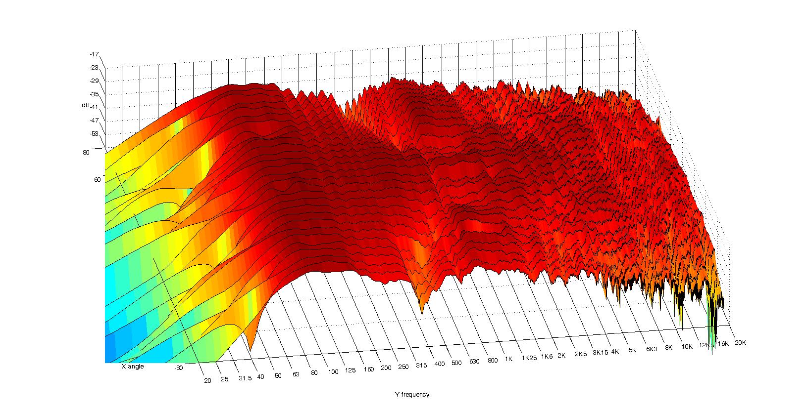
Is the Y-axis degrees, not dB? What was the measurement setup? I'm also curious to find out how the "calculated" beamwidth was derived. Sure, I haven't tried to measure the polars in-room. Chris . Measuring polars in my world means taking the device under test (DUT) and mounting it on a motorized turntable in the parking lot and making ground-plane measurements. The DUT polar behavior will depend on the size and shape of the baffle in which it's mounted. So an adapter has to be made that somewhat mimics the speaker system in question *and* readily adapts to my turntable. If you are interested in providing something for measurement, let's have a discussion of all the details... Also, I don't view directional data as polar plots. I view directional data as seen in the attachment. The horizontal axis is log frequency, the front to back axis is angle (the example data set has on-axis in the center) and the vertical axis is response magnitude in arbitrary dB. My measurement environment limits low-frequency capability, so the data below 200 Hz should be viewed with a raised eyebrow. ************************************************************************************************************************************************************************* *Beware that real speaker measurement data is ugly, almost all curves seen in reviews, datasheets, etc have been smoothed by the marketing pen* ************************************************************************************************************************************************************************* A perfectly flat omnidirectional speaker would have flat lines across all the measured angles. The data can also be normalized to the on-axis response so only the directional differences from the on-axis response are displayed.
-
My K-Horns are in a larger room now...
Greg Oshiro replied to Greg Oshiro's topic in 2-Channel Home Audio
See the following for a discussion on that point: http://forums.klipsch.com/forums/p/154887/1631781.aspx#1631781 http://forums.klipsch.com/forums/p/154887/1631050.aspx#1631050 Chris One of these days I'll clear out the stuff in-between the speakers and listen. But the immediate project is finding a place for some WAF items that got displaced by the audio takeover in the big room. Regarding the imaging FAQ, are there any polar data on the K-402? One of these days I'll either find a top hat that I can abuse and measure polars, or build an acoustical equivalent and measure polar behavior. I'm not willing to take my WO top hats out to the parking lot to measure them. If you're willing, we can measure your K-402's someday. I did discover that the position of my head (inches!) makes a huge difference in imaging. This makes me more interested in measuring polars. -
My K-Horns are in a larger room now...
Greg Oshiro replied to Greg Oshiro's topic in 2-Channel Home Audio
I have mixed feelings about the D75's. I had to change the internal grounding to reduce the hum/buzz. Unfortunately, this caused an increase in distortion. So I'm not too confident about the amps right now. I usually get blinking green Lights on woofers and squawkers. Tweeter amps are always dark. I did crank it up to get IOC lights on the woofer amp in the old room, but I was being stupid... I got started on a "really good 5-watt amp" (solid state) awhile ago, but that project languished like so many others... What crossover settings do you use? . -
My K-Horns are in a larger room now...
Greg Oshiro replied to Greg Oshiro's topic in 2-Channel Home Audio
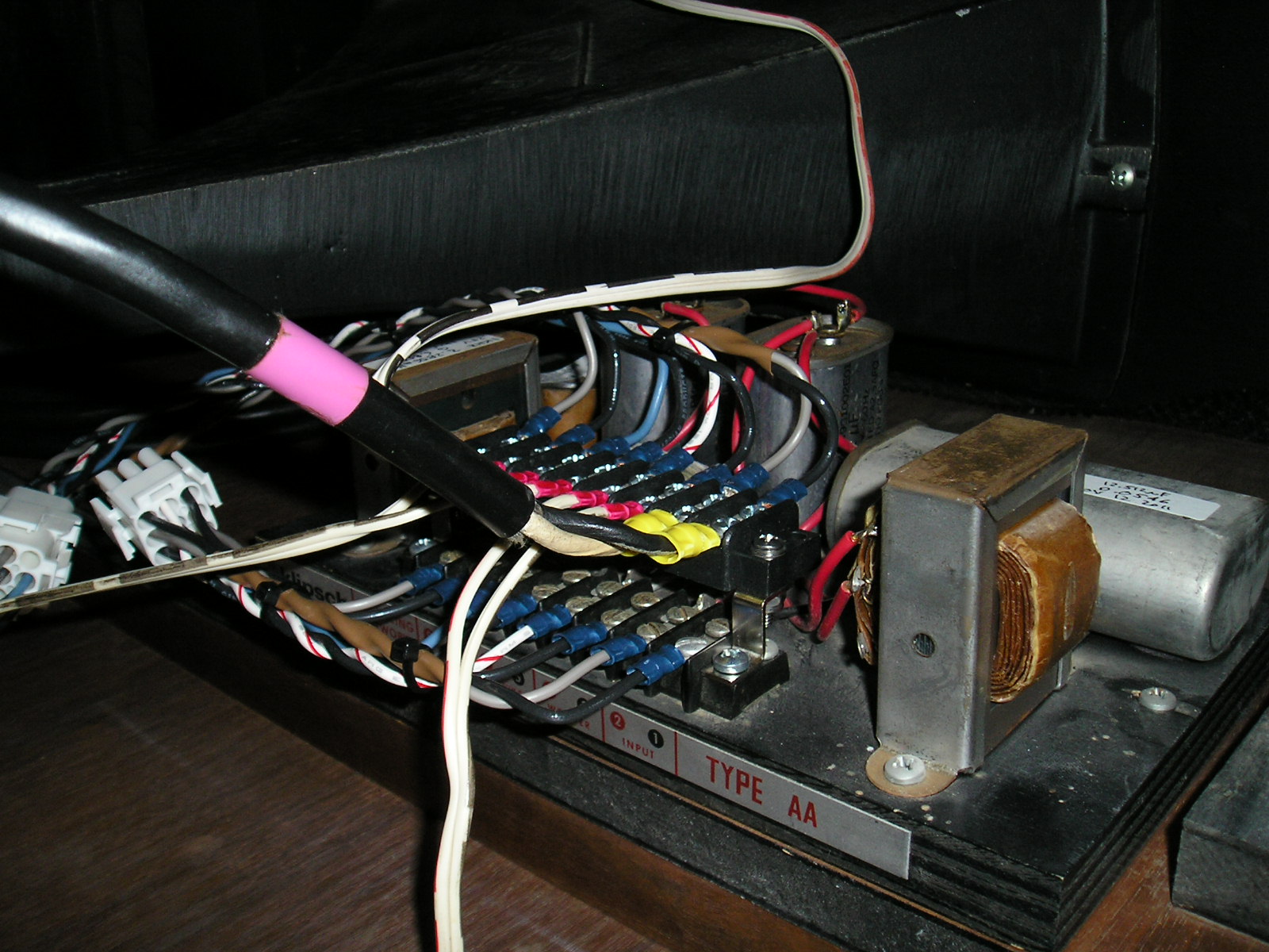
A closer view of the mod around the crossover.
-
My K-Horns are in a larger room now...
Greg Oshiro replied to Greg Oshiro's topic in 2-Channel Home Audio
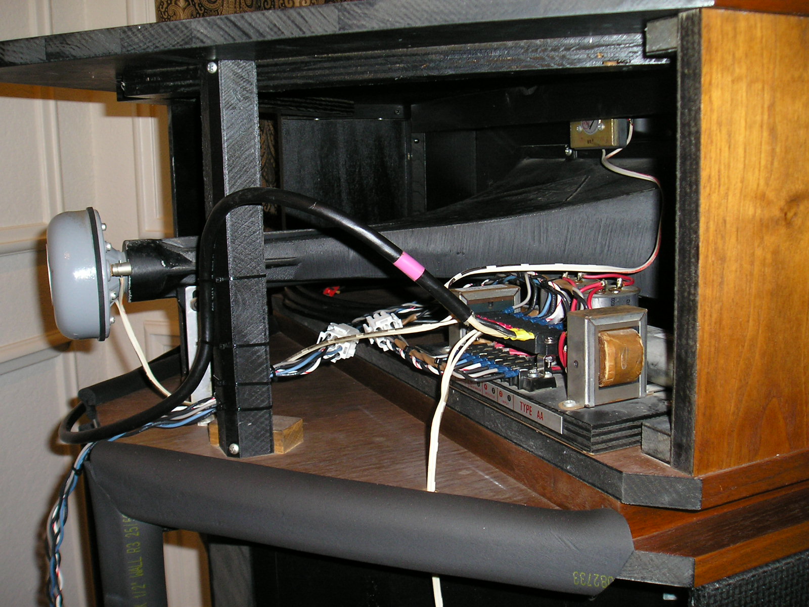
Here's the wiring mod around the passive crosssovers. The white plastic connectors can be patched to select either: The full-range amp feed (black jacketed cable with violet tape) and AA Xovers are connected to the drivers *or* The triamp feeds (three twisted pairs dropping down near the tailboard) are connected to the drivers.
-
My K-Horns are in a larger room now...
Greg Oshiro replied to Greg Oshiro's topic in 2-Channel Home Audio
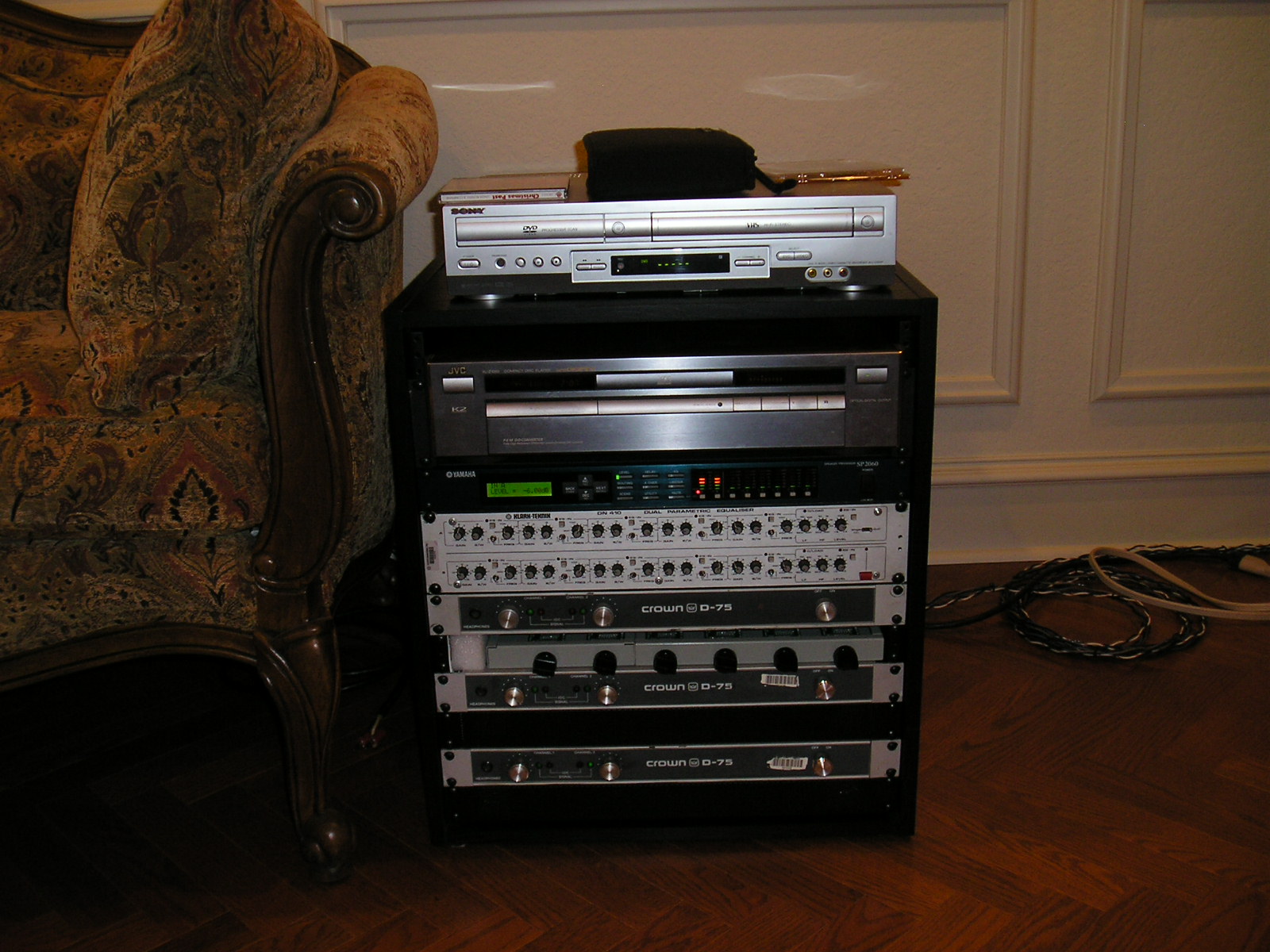
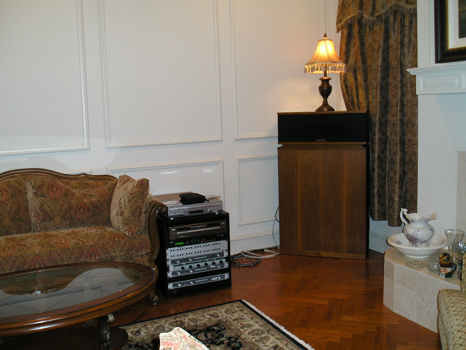
Here's a close-up of the rack: Cheesey Sony DVD player (audio only in this room) JVC CD player Yamaha DSP Klark-Teknik stereo parametric EQ (used when using passive crossovers) Tweeter amp Custom 6-channel balanced passive attenuator ( -0.5 dB, -6.1 dB, -12.1 dB, -18.1 dB. -26.1 dB, -30.1 dB, -36.1 dB, -42.1 dB) all accurate within .038 dB error band. Normal listening is at -36.1 or -30.1 dB. Squawker amp Woofer amp
-
My K-Horns are in a larger room now...
Greg Oshiro replied to Greg Oshiro's topic in 2-Channel Home Audio
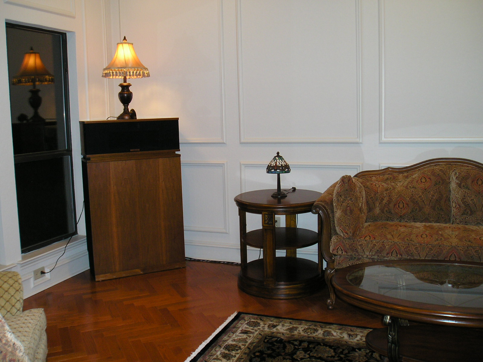
Left side viewed from behind the listening position.
-
My K-Horns are in a larger room now...
Greg Oshiro replied to Greg Oshiro's topic in 2-Channel Home Audio
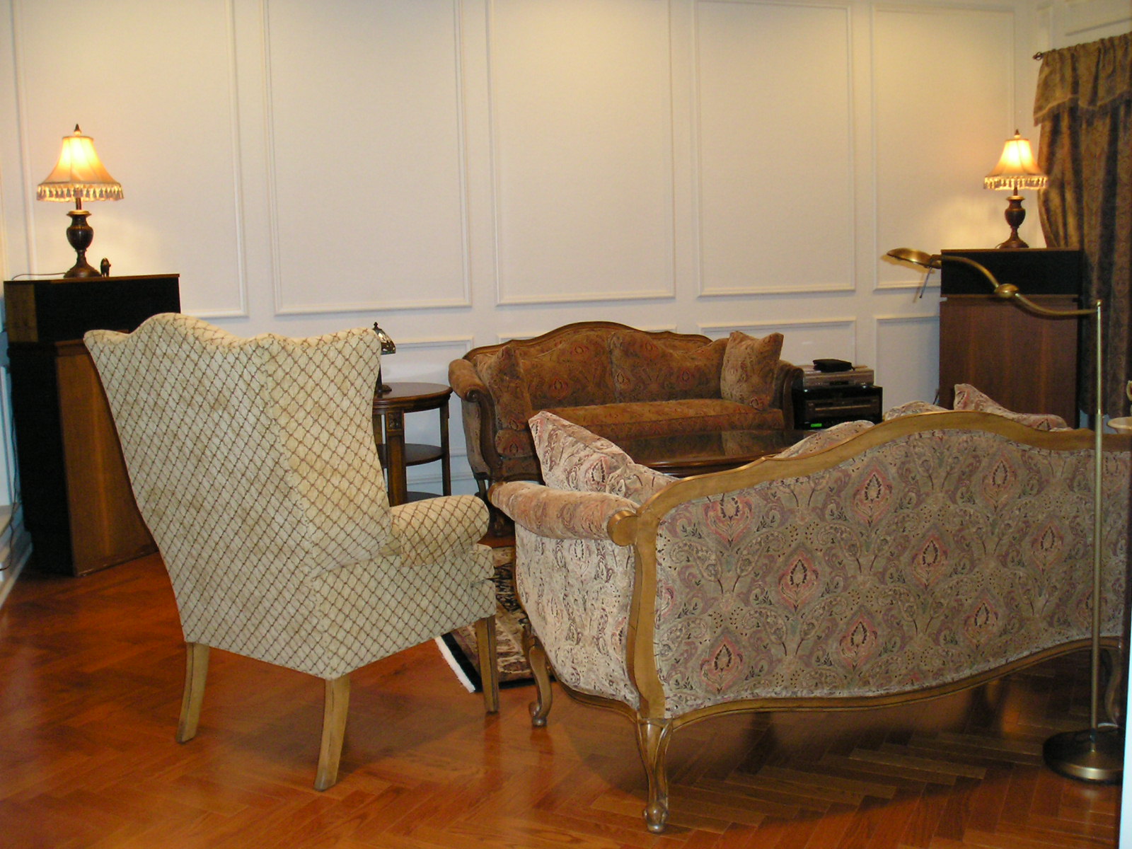
Right side viewed from behind the listening position.
-
I moved my triamped Klipschorns (http://community.klipsch.com/forums/t/156476.aspx) from the short wall of the TV room (12'-6" X 17'-6" X 9' ceiling) to the long wall of the living room (19'-6" X 15'-8" X 10' ceiling). My ears are about 11'-6" from the K-Horn wall, just beyond the intersection of the two speaker axes. Some program has a bit of a hole in the soundstage, some doesn't. There is a vertical room mode that makes things sound thin when standing just in front of the normal listening position (when I get up from the couch). The low end sounds great when sitting on the couch, and that's a good thing. More pics below
-
Ready to invest in some acoustic panels
Greg Oshiro replied to Heritage_Head's topic in Home Theater
It's my understanding that the absorption vs. frequency characteristics depend on the space behind the panel. IIRC greater space behind the panel improves LF absorption. So I think the spacing will depend on what frequencies we intend to absorb. -
Polar response ??? for K107T1 and T35
Greg Oshiro replied to moray james's topic in Technical/Restorations
Don-- Those plots correlate with what I hear. The rear-mounted off-axis curves are much worse than the front-mounted. I don't have the woodworking capability to enlarge the tweeter holes to accommodate the Z-brackets without damaging something. Maybe I'll get new motorboards from Volti someday if Greg's still doing K-horn mods. The first item on the list is measuring what I'm currently listening to so I have baseline data. --Greg -
Polar response ??? for K107T1 and T35
Greg Oshiro replied to moray james's topic in Technical/Restorations
Yes and yes. There are some practical considerations, though. The tweeter's polar behavior will depend on the size and shape of the baffle in which it's mounted. So an adapter has to be made that somewhat mimics the speaker system in question *and* readily adapts to my turntable. If anyone is interested in providing something for measurement, let's have a discussion of all the details... Also, I don't view directional data as polar plots. I view directional data as seen in the attachment. The horizontal axis is log frequency, the front to back axis is angle (the example data set has on-axis in the center) and the vertical axis is response magnitude in arbitrary dB. My measurement environment limits low-frequency capability, so the data below 200 Hz should be viewed with a raised eyebrow. ************************************************************************************************************************************************************************* *Beware that real speaker measurement data is ugly, almost all curves seen in reviews, datasheets, etc have been smoothed by the marketing pen* ************************************************************************************************************************************************************************* A perfectly flat omnidirectional speaker would have flat lines across all the measured angles. The data can also be normalized to the on-axis response so only the directional differences from the on-axis response are displayed.
-
Polar response ??? for K107T1 and T35
Greg Oshiro replied to moray james's topic in Technical/Restorations
I was going to post a similar question, but you beat me to it. I've been noticing that my Klipschorn tweeters (K-77/T35) sound like they have very narrow horizontal dispersion. My K-horns have the tweeter mounted on the back of the motorboard. If anyone in the DFW area has a top hat that is in poor cosmetic condition which I can borrow (and likely return in *worse* cosmetic condition), I'm willing to make some polar measurements and post them here. I'm not willing to take furniture-grade finished top hats into the parking lot for measurements. Transducers need not be included with the top hat. Grille cloth must be installed. I am willing to transplant my horns/drivers for these measurements. Another option might be a dimensionally accurate top hat copy with grille cloth installed. Do any of the woodworking forum members have a top hat that didn't turn out quite right? -
Ready to invest in some acoustic panels
Greg Oshiro replied to Heritage_Head's topic in Home Theater
The "industry standard" panel material is Owens-Corning 703 fiberglass board, 3 pounds per cubic foot (pcf). The edges are hardened with resin and the panel is covered in fabric that lets the fiberglass do most of the LF absorbtion. I've seen 703 on ebay. Maybe roll your own? --Greg -
Ouch!! I hope the recovery goes well. --Greg
-
Chris-- Count me in. What's your preferred beverage?
-
How to make my system sound better?
Greg Oshiro replied to dachuckster's topic in 2-Channel Home Audio
I was once heard a rumor that this works: Temporarily place one of your speakers at the listening position. The tweeter should be in the "sweet spot" where your ears would normally be. In your situation the couch will probably have to move back a bit. Use temporary low-resistance speaker cable. Play program through the "sweet spot" speaker only. Place your head in the candidate speaker locations and listen. You'll have to get your head at the same height above the floor that your woofers will be to evaluate low-frequency balance. The best sounding candidate positions, one left and one right, are where the speakers should go. I've never tried it, but there's some strong theory behind the concept. I see from your posted pix that the listening space is not symmetric. That stacks some of the cards against you. I also agree with the previous poster(s) regarding the equilateral triangle being the optimum setup. Having grown up in Minnesota and living in warmer climes for a long time, I don't envy you the winter, but I do miss the neighborly quality of MN folk. -
Klipschorn Compatibility � The Math
Greg Oshiro replied to AnalogWave's topic in 2-Channel Home Audio
Radio Shack has a 90-degree F adapter.