mboxler
-
Posts
574 -
Joined
-
Last visited
Content Type
Forums
Events
Gallery
Everything posted by mboxler
-
A first order filter is doesn't do much within a couple hundred Hz either side of resonance. If everything was perfect (2.4 mH inductor, 6 ohm load, 400 hz), the voltage to the K-33 is down 3 dB. At 500 Hz, it's down 4 db. At 600, around 5 dB. If both the K-33 and K-55 were perfectly crossed (first order) at 400 hz, they would each be down 3 dB. The voltage across both drivers combine at 400 hz, resulting in a 0 dB summed voltage. It would be a 3 dB bump when summed, but the voltages across each driver is 90 degrees apart. As you can imagine, even if the K-33 were crossed at 400 hz and the K-55 at 500 hz, the combination would be down less than .5 dB around 450 hz (I didn't do the math). Too little to make any difference. Again, this is voltage only. Driver sensitivity, cabinet, room, and kids will change everything. That's my theory anyway! Mike
-
Thanks for doing that! Odd that the impedance is lower at 50 hz in the horn than in free air (which I assume is the black graph). Mike
-
I'm bummed. At 60 Hz, I get around 4 ohms. At 1000 hz I get around 7 ohms. Could my K-horn's not be sealed well enough against the wall, or did I just waste time with this technique.
-
You caught on to my motivation. I saw that plot. Perhaps I'll try this at 50 hz and see if I'm still in the ballpark.
-
I would like to measure the impedance of the K-33 in my K-horns at 400 hz. I've assembled a "patch cable" to place between my amp and the bass bin. The cable contains a 101.5 ohm 10 watt resistor that will end up in series with the woofer. The resistor actually measures 101.5 ohms. I have a free product on my Windows PC (fg_lite from Marchand Electronics) that allows me to generate the 400 hz signal. The chain will be PC-->DAC-->amplifier-->speaker cable-->patch cable-->right K-horn bass bin binding posts. These binding posts are connected directly to the K-33. When the signal is generated, I will turn the amp up until the tone becomes somewhat loud. I will use my Fluke 115 Trus RMS meter to measure the voltage across the right amplifier binding posts. I'll call the Vin. I will then measure the voltage drop across the 101.5 ohm resistor. I'll call this Vr. I will then calculate the current through the resistor. This will be Ir. Ir = Vr / 101.5. I will then calculate the voltage drop across the K-33, which should be Vin - Vr. I'll call that Vk33. Since the current passing through the resistor must be equal to the current through the K-33, I can calculate the impedance (resistance) of the K-33, I'll call that Rk33. Rk33 = Vk33 / Ir. This is what I ended up with... Vin = 6.325 volts Vr = 5.995 volts vk33 = .33 volts (man that's loud!) ir = .059 amps Vk33 = 5.887 ohms Does this method correctly measure the impedance of the K-33 at 400 hz? If so, I think I'll plot a few other frequencies just for fun. Sorry if this has been tried before. Thanks, Mike
-
Here's another great article. It made me realize that drivers with 2nd order passive crossovers are not really 180* out of phase with each other. http://www.bcae1.com/compleximpedance.htm Mike
-
In reality, reactive components in series/parallel yield weird(?) results. Yes, the voltage and current differ by 90*, but when placed in a complex circuit, like a crossover, this get a little complicated. Let's take a simple first order crossover, 8 ohm woofer, 8 ohm tweeter, crossed at 1000 hz. The capacitor in series with the tweeter would be 19.88uF and the inductor to the woofer 1.27mH. At the resonance frequency (1000 hz), the impedance of the capacitor is 8 ohms @ -90*, the impedance of the driver is 8 ohms @ 0* However, the total impedance thru this circuit is 11.318 ohms @ -45 degrees. The woofer circuit is 11.318 ohms @ +45 degrees. If you pass a 10 volt 1000 hz signal thru the 11.318 ohm circuit, it will draw .8836 amps. Since the current thru the series circuit is the same as the current thru each component in the circuit, then .8836 amps thru an 8 ohm driver will be 7.07 volts, or -3 db. If the phase shift between the two drivers were identical, then a 1000hz signal to each driver, even though down -3db, would combine to give a +3db output bump. But the 90* phase difference between the two drivers eliminates the bump, because when the voltage to one driver is at it's peak, the voltage to the other driver is zero. I hope this makes sense. Here's a link to an interesting calculator. http://keisan.casio.com/exec/system/1258032632 Sorry if this doesn't answer your question. Second, third, and so on order filters get really interesting. Mike
-
Maybe this old thread from ALK will help??? https://community.klipsch.com/index.php?/topic/106102-developing-a-network-for-the-forte/&tab=comments#comment-1168913
-
Sorry if you already understand this, but just in case... The Antek transformers are designed for 115 /230 volts. If your voltage is higher, the output will be higher as well. Last summer, our voltage spiked to 133 volts for quite a while until the power company finally fixed it. Is Sure power supply you referenced designed for + / - DC outputs?. If you used the same an4434 transformer wdecho used and wired it for 115v (inputs parallel, outputs series), you'll get both a + 48 volt dc output and a - 48 volt output. You would only use 1 of the outputs. I guess if you wired the inputs in series (which I assume wdecho did???), then you would get +24 and - 24. You would then hook up your amp ground to -24 and positive to +24, which is the same as 0 and +48. I hope I got that right. Mike
-
This chart comes from Bob Crites web site... http://www.critesspeakers.com/3636atz.pdf As you can see, if you measure the inductance between taps 0-5, divide it by 2.833 (9db), you should get the inductance between taps 0-2. If you have a good DCR meter, I believe you can accomplish the same thing. I measured the DCR on a 3619 autoformer. .37 ohms between taps 0-5. .14 ohms between taps 0-2. .37 / .14 = .2.64. My meter only carries out to 2 decimal places, so this falls between 8 and 9 db attenuation. Would you agree djk? Mike
-
My guess...a T10A autoformer, which will reduce the voltage by 9dB. You would need to pass a low voltage sign wave across 0 and 5 and measure it. The voltage across 2 and 5 should be equal to .3535 times the input voltage. You would need a true RMS meter to measure the voltage. Mike
-
Would it not be more flexible to place a 26uf cap after the autoformer? Seems that you could change the output taps to whatever value you want without the need to change the cap. Mike
-
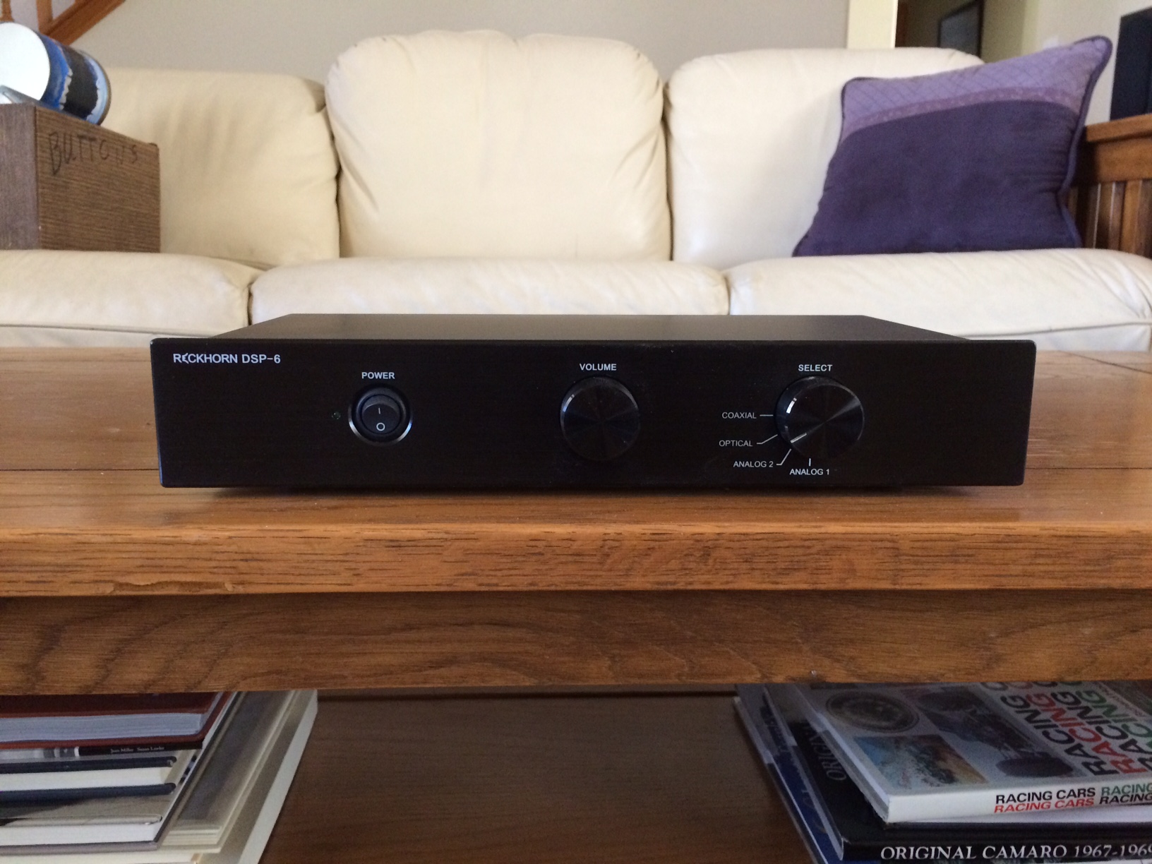
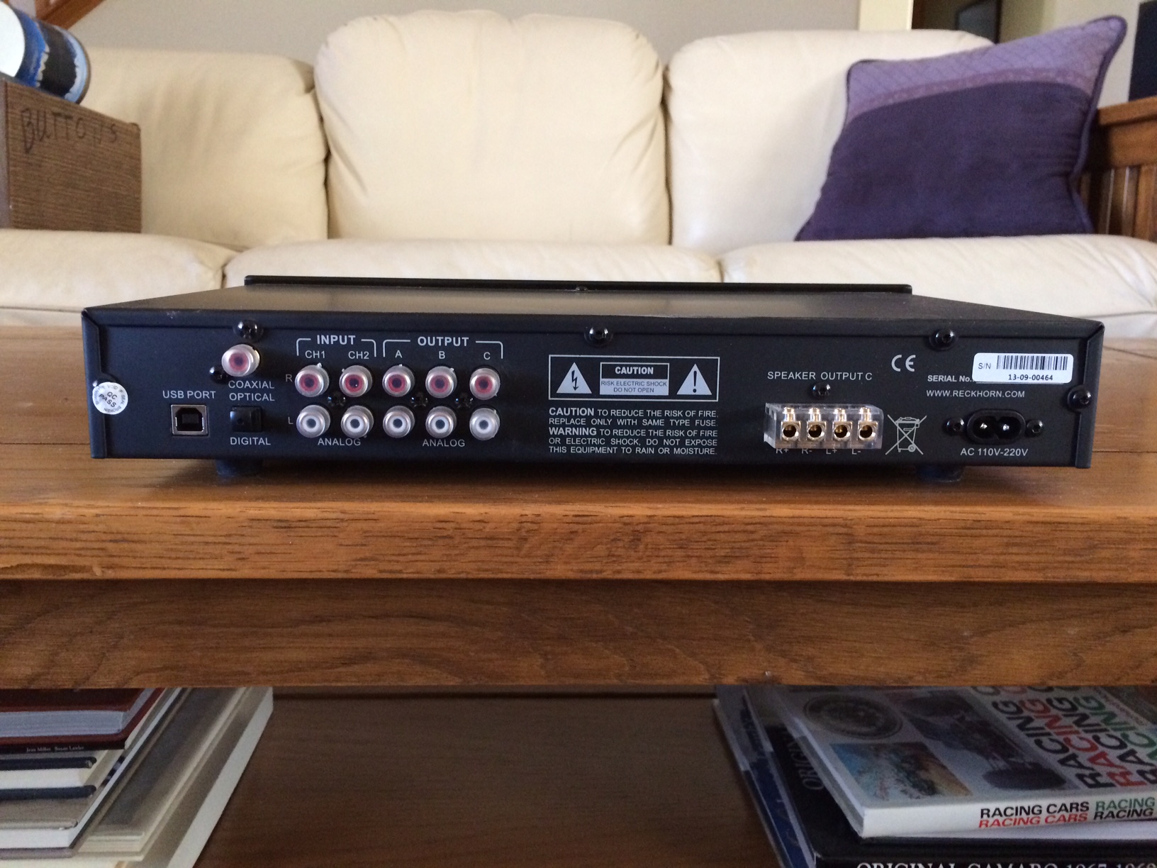
Like new Reckhorn DSP-6 digital crossover, purchased new 2 years ago. Could never get a manual, but I was able to figure out the basic way to configure. I'll be happy to preload the unit with a specific configuration if requested (slopes, crossover points, delays, gain). According to the webpage... "The program is running on all operating programs Window XP to Windows 8 up to 32-bit, but not on 64-bit versions and Apple." I installed it on Windows 7, and it still running on 64 bit Windows 10. Original box. Will include a better USB cable than the one shipped with the unit, as I was having trouble connecting with the stock cable. https://www.reckhorn.net/pages/active-x-over/dsp-6-digital-speaker-crossover.php http://www.tnt-audio.com/sorgenti/reckhorn_dsp6_e.html Currently selling new on Amazon for $399. $175 shipped to conus, including PP fees. Mike

-
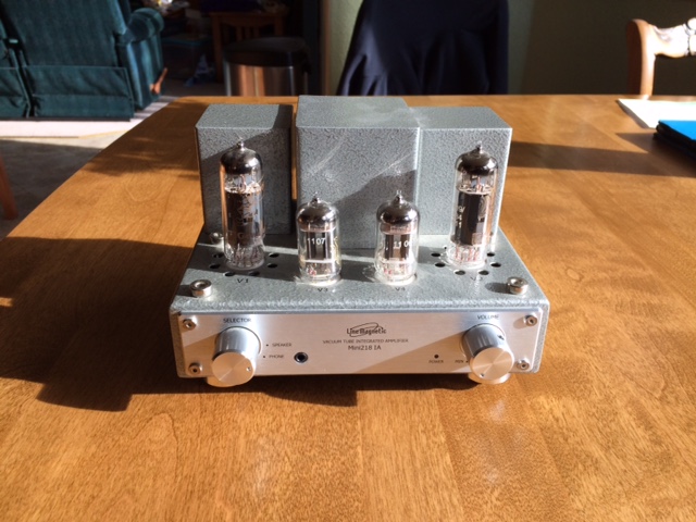
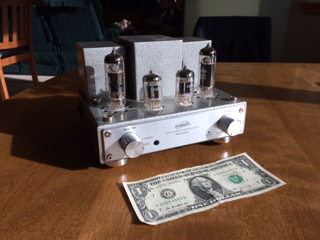
Purchased from original owner in 2013. Very clean, very compact SE EL84 integrated. A hefty 3 watts output, 4 and 8 ohm speaker taps, 1 input, volume control, headphone/speaker switch, IEC C7 power cord. You will get the original Line Magnetic EL84s and 12AX7s, as well as Genalex re-issue N709/EL84s and ECC83s. Original box. Purchased from an authorized dealer -- not gray market. I will also include a cryo'd C7 power cord from Iceageaudio. No cage. No manual, but here's a link to the pdf. https://www.line-magnetic.eu/images/line-magnetic/pdf/Manual-LM-218IA-MINI-web.pdf 120 Volt version. Mike
-
Probably a dumb thought, but can a metal-cased capacitor be placed that close to an inductor? I think it's okay for other capacitor types. It's almost as if the capacitor value is higher at lower frequencies.
-
If you reused the T3A autoformer, I believe it is set for -6db. The stock AA uses tap 4 of a T2A, I think, which is only down 3db. Maybe it is more of a dip then a bump???
-
I've had the DE-5000 for a while. Only drawback...the short alligator test leads, Bought this, hoping it would fit the DE-5000, and it does. Main issue with this though, is the clips don't grip very hard and the cable is pretty stiff. But the added length comes in handy. https://www.amazon.com/gp/product/B005T710WG/ref=oh_aui_detailpage_o00_s00?ie=UTF8&psc=1 Mike
-
I own it's big brother, the 4X10 HD. It runs around $500, but has more outputs and physical volume control. No USB audio, though. In fact, I'm testing my almost completed Lxmini's with it now .
-
Sorry if you know this already, but... The -3 db point of a first order filter occurs when the Z of the capacitor equals the Z of the driver at a given frequency. Assuming an 8 ohm tweeter, a 4 uf cap's Z is 8 ohms at 4975 hz. When a 4 uf cap is in series with a 13 uf cap, you will end up with a 3 uf cap to the tweeter. A 3 uf cap will be down 3 db around 6630 hz. The 6.8 uf cap in series with a 4 uf cap equals around 2.5 uf, crossing around 8000 hz. My point is, if the caps are in series, as you change the squawker cap you are also changing the -3 db point to the tweeter. Also, I assume you are using one for Bob's tweeters? Off to do Xmas shopping!
-
I agree with the swamper idea, but very large capacitance (approx. 48 uf per channel) would be needed. Still curious about the wiring. Do you have a picture from directly above the crossover?
-
I'm curious. I can't tell from the picture, but it appears that you wired the 4 uf tweeter cap directly to the crossover input. The schematic shows it wired to the output of the squawker cap, which would create a series circuit to the tweeter...constantly changing the capacitance to the tweeter as you change the squawker cap.
-
I found this interesting... https://www.qacoustics.co.uk/blog/2016/06/08/bi-wiring-speakers-exploration-benefits/
-
It seems to me that, once you have separated the crossover, the impedance to the woofers and tweeter will change. With the strap in place, or bi-wired without the strap, the two crossovers are wired in parallel. As the signal frequency lowers, the impedance to the woofer lowers while the impedance to the tweeter increases. In parallel, the impedance seen by the amplifier will be less than the lowest of the two. Without the strap, and bi-amped, the woofer amplifier will see a quickly rising impedance as the frequency increases. The tweeter amp will see a rising impedance as the frequency drops. As discussed in another thread, can your tube amp handle the high impedance?
-
Bump
-
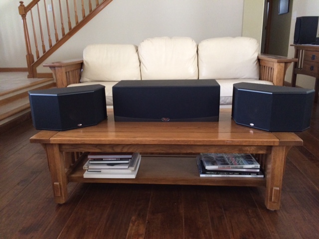
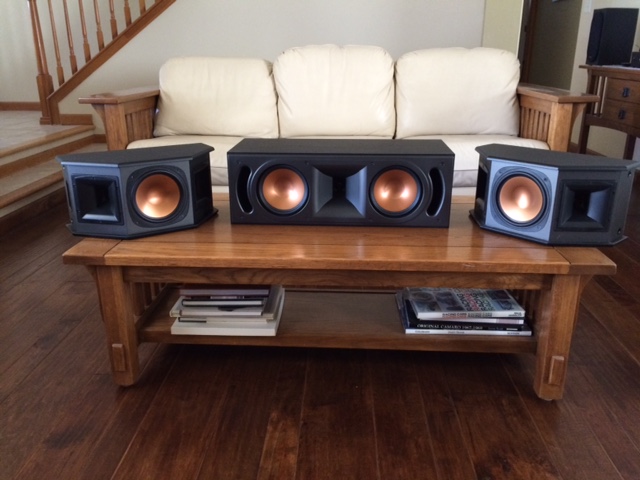
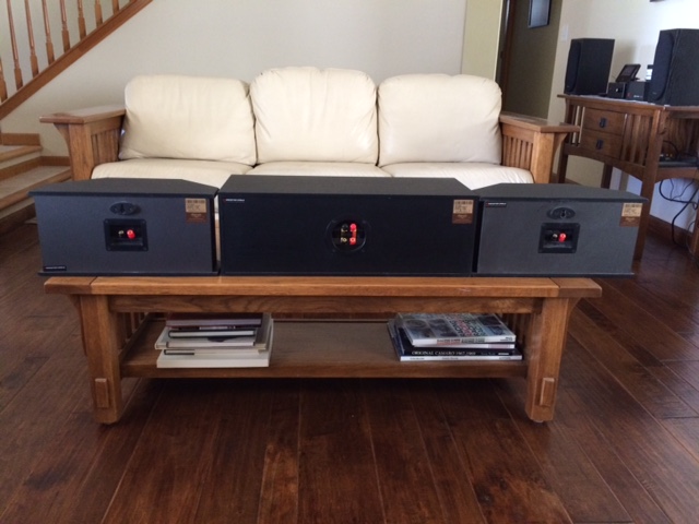
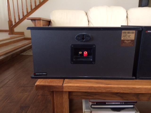
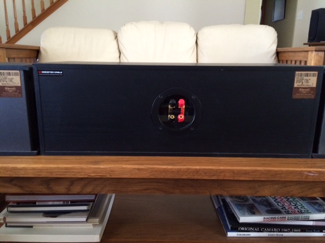
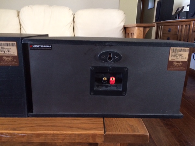
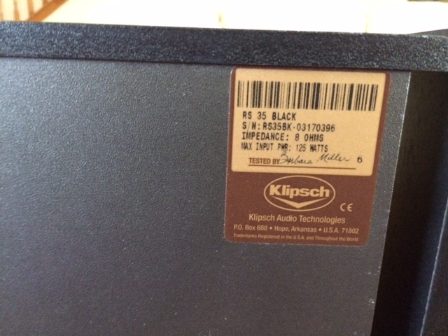
Original owner. Smoke free environment. Prefer local sale. I do not have original boxes. There is a pair of RF-35's on craigslist if you want matching front speakers. RF-35