captainbeefheart
-
Posts
1422 -
Joined
-
Last visited
Content Type
Forums
Events
Gallery
Everything posted by captainbeefheart
-
And it will perform better than much more expensive single ended tube amps and you'll get the same voicing as a tube amp. 1% THD at 5 watts. Don't get me wrong you can make a 5 watt single ended tube amp with the similar distortion figures but the most common 5 watt tube amps I find have more than 1% THD. I find it hilarious that most engineers will only use lateral Mosfets because of the negative temp coefficients for their designs yet Nelson Pass comes along and uses the cheap and much more common vertical Mosfets and most people love his amps. Again Nelson going against the grain and carving out his own niche.
-
If there is a large enough interest in making this amplifier but a problem of getting the boards there is a possible solution. I have the board layout in a pdf and can make copies of it for sale. It's very simple and should only take me an hour or so to make the gerber files. Then I can email the file and have 10 or so boards made up. I am limited to computer work right now with my back out. This sucks big time.
-
Little Sweetie Forum amplifier project
captainbeefheart replied to henry4841's topic in Talkin' Tubes
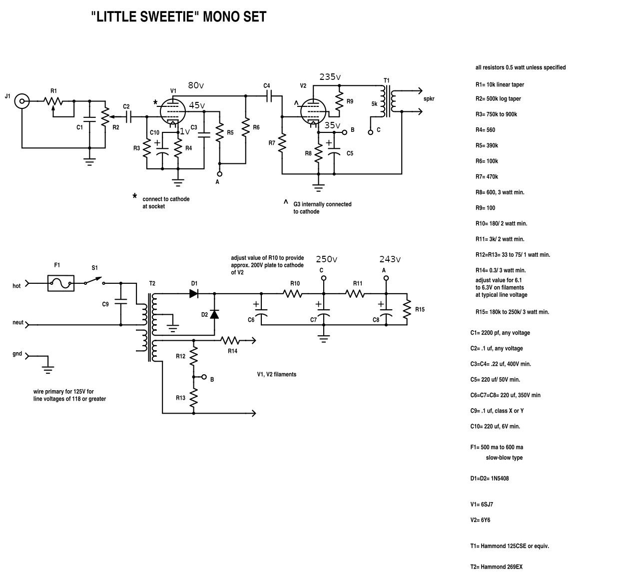
I annotated the schematic to add the voltages since it's much easier for beginners to read them there than to look up tube datasheet and find the pins for the corresponding electrodes. Hope it helps
-
Little Sweetie Forum amplifier project
captainbeefheart replied to henry4841's topic in Talkin' Tubes
Tubes are very forgiving and much easier to start out making amps with vs SS. As mentioned it's often a daisy chain effect where the entire output stage transistors fail along with many of their components to make them work. I still recommend a preliminary check of voltages before buttoning the amp up. That means clip the ground lead to your meter to ground, keep one hand in pocket and use the other hand to probe different areas in the amp to make sure you have the correct operating points. B+ feeding the OPT should be ~250v 6Y6 Plate- 235v Cathode- 30-35v *depending on the tube some may draw more current than others so you get different readings. Grid- 0v 6SJ7 Plate- 80v Screen- 45v Cathode- 1v Grid- 0v Once these voltages are confirmed then it should be okay to move forward. For those that read here to learn, a small correction on the instructables definition of a tube and transistor taking a small current and making a bigger current is true for a bipolar junction transistor but not for a tube or Mosfet. A vacuum tube has transconductance which means it's a voltage controlled device, not current controlled. The grid doesn't require current like the base of a BJT. Transconductance just means that for a given input change of voltage we are given a specific output change in current. For example a 12AX7 has a transconductance of 1600uMhos, that means for every 1v change at input you get 1.6mA change through device. Transistors have beta or technically "hfe", which is strictly current gain. An "hfe" of 100 means with 100uA of current through the base to emitter forward biased diode you will get 10mA current from collector to emitter. Now there are some transistors that are very similar to certain tubes, pentodes to be specific and they are Mosfets. Both have transconductance, both have very similar output characteristics and both are voltage controlled current devices. Just wanted to clear up the different types of transistors and how they function compared to a vacuum tube. This leads me to one huge thing one should take away from that. In that in the family of "tubes" they can behave very differently. So when someone says "tubes are more linear than transistors" that is not true because a Pentode is a tube and it has similar output curves to transistors. So triodes and Pentodes are vastly different in characteristics. In fact a triode is linear due to internal negative feedback. Simply the plate voltage also controls the current through the device, so as the plate swings down towards ground current decreases, as the plate swings up near supply voltage current increases. This is feedback. The engineers went in and added another grid to shield this mechanism which is why the output curves changed so drastically. As you'll notice looking at the plate curves for Pentodes they have straight lineas across horizontally not vertically like a triode. That horizontal line is plate voltage and it's horizontally flat because current doesn't change vs the plates potential. Looking at a triode as the plate curve goes more negative it gets moved down in current making the curves more vertical. So when you are in your next tube vs SS argument you can make the distinction of triode vs transistor because really a pentode behaves more like a transistor in regard to it's output characteristics. i.e. the collector voltage doesn't have any effect on collector to emitter current, it's controlled via base to emitter current only. This is also why you get a lot more power out of Pentodes vs Triodes, as the Pentode swings it's plate low there will be no reduction of current through the device. -
I'm guessing you mean a 299c? Does it have 7591 power tubes? If it hasn't been powered up in a while then I advise bringing it up slowly on a variac. I go a step further and remove the loads from each power supply node and current limit the capacitors with a series resistor in series with rectifier. I find it easiest to just remove the wire from the rectifier going to the cap can. Then I use a DC meter in series to power the cans while monitoring current. Once you get them up to rated voltage slowly I monitor leakage current. If it's above a specific amount I move onto finding which one is suspect and replace it. It's usually the one right after the rectifier as that sees the most ripple current. I'd say from the Scott if you have less than 1mA of DC leakage current for all the caps combined then it's fine to move forward. The point is to slowly reform the capacitors back into healthy operation. If it's been running in the last year then forget all of this. The best way is to clean is to remove everything and send the chassis off to a have it cleaned in an ultrasonic bath. I'm not crazy picky and I find just a damp rag is adequate to clean. If it's really dirty dawn dish soap and a soft bristle brush, scrub in local areas then wipe dry with damp cloth. For corroded rusty parts of the chassis I use Naval Jelly, let sit for 15 minutes and rinse clean, I use a spray bottle of waterto squirt at the problem area then wipe off with towel. Do not use that stuff on decorative faceplates or on silk screened print. Only meant for the steel chassis where you have rust. I believe the 299c uses a Selenium rectifier for the 150mA filament string and power tube bias supply. Replace with Silicon diodes, you'll most likely need to add some series resistance to get it down to -40v due to the lower forward voltage drop of Silicon. There is a string of RC filters to clean up the negative supply and drop the voltage down, all resistors are 18 ohms, try replacing the first one with 30 ohms I believe is the right value to get the desired drop back to normal. The 333 may also have a Selenium rectifier for it's B+, if so remove and replace with Silicon. Don't worry too . much about the voltage when switching over here, it's high voltage and a few extra volts is fine. With the 299c the filaments get powered by the negative supply and so it needs to be accurate. Too high a voltage for filaments will shorten the life substantially. Great amp! Enjoy!!
-
AA Crossover severe heat problem
captainbeefheart replied to Dave A's topic in Technical/Restorations
I removed my zeners from my La Scala's so I could do an experiment. I have some very beefy transformers around that could push 10 amps. Basically start at 1/2 an amp and see how hot it gets, keep increasing current until you find where they get the bracket hot enough to melt the insulation. -
AA Crossover severe heat problem
captainbeefheart replied to Dave A's topic in Technical/Restorations
Yes I'm very familiar with the circuit. The tweeters can only handle a couple watts which is 4Vrms, or 5.6v peak. The diodes start to conduct around 5.1v clamping the voltage to that maximum amplitude thus protecting the tweeter from seeing too high an amplitude and fry it. If I were in your shoes I would strongly advise your customer to have his amplifier inspected by a professional, or at least someone that can hook it up to varying loads (some capacitive loading get's marginally stable amps to show themselves) and see if it's stable. The picture is clear to me that the wire only melted when in contact with the zener bracket/heatsink. This tells me the heatsink is what got hot and it doesn't take a lot to melt the old PVC insulation. The black wires were touching the heatsink in very close proximity to the diodes themselves where it would be hottest. Down below where it has good contact with the wooden board could have dissipated off enough heat to not damage the red wires that look to also be touching but to no extent as much as the black wire. It's not uncommon for amps to become unstable and oscillate at a high frequency we cannot hear, I typically find them between 30kHz-60kHz. The amp could have been putting out full power at that frequency which the zener's would clamp and dissipate off the extra power so it doesn't go into the tweeter. DC from the amp would have caused an awful noise through the woofers and most likely destroy the thin magnet wire of the voice coil rather quickly, if the voice coil held up long enough to melt the wiring it would show in the low pass inductor because it's magnet wire is fairly thin and probably damage easily if the voice coil held up longer. Typically the voice coil burns up pretty fast thought saving the internal components and wiring of loudspeaker. I'm not a betting man but I'd certainly put my money on high frequency oscillation caused from the amplifier that damaged the wires from zeners getting hot from doing their job and protecting the tweeter. -
Little Sweetie Forum amplifier project
captainbeefheart replied to henry4841's topic in Talkin' Tubes
Maybe in future projects I can do that but right now I am so swamped I'm sure Shakey and Westcoastdrums just want me to get them done ASAP and not waste time taking pictures and educating people. I'll of course post gut shots soon but I can't do any in depth write ups at the moment, it wouldn't be fair to them to waste time. Of course my back's been out the past few days so I've been slowly tinkering but mostly just resting because I can't really move or walk at any reasonable pace. Getting old and abusing my body with sports and whatnot as a youth isn't fun. -
Little Sweetie Forum amplifier project
captainbeefheart replied to henry4841's topic in Talkin' Tubes
I'm not trying to change the schematic or design, I apologize for some mod suggestions, it was only for people that build this and might want to tinker with it a bit. I'll hold off on that talk and stick to the original implementation. Now for the power supply discussion, although people might be construing it as a "mod" and "different" from the schematic the conditions are quite clear on the schematic of having 200v across the 6Y6, plate to cathode. So I disagree with people saying the discussion is not part of the original design, the goal is to get the same operating point as Maynard got with his mono amps but with a stereo amp. I know the transformer Henry got and I know the circuit and the 6Y6 operating point from the schematic. I'm only trying to help you achieve what was intended by Maynard in the circuit design. Going with a 560 for R10 will leave you with only 155v across the 6Y6 which is not the design. I also just added voltages for the driver tube to help builders know they made the circuit correctly by checking against the voltages on the schematic that I provided. Sorry I won't try to help if that's what is wanted. I'm really not trying to change anything, I crunched the numbers and agreed a choke even with a Stereo unit probably won't lower the noise enough to warrant the change. It's a nice circuit, I just want people to get the most out of the design by getting the correct 200v across the 6Y6. I'll bow out if that's what is wanted. -
Cheap Forum Amp by Captainbeefheart
captainbeefheart replied to MEH Synergy's topic in Talkin' Tubes
Thank you!! Let me know if he needs any more information. -
Cheap Forum Amp by Captainbeefheart
captainbeefheart replied to MEH Synergy's topic in Talkin' Tubes
Wow! Great news Nick and thanks for asking him. Here are the specs: Load: 3k:8 DC current: 100mA Inductance and power: Flat to lets say 35Hz with a source impedance (Tube plate impedance) of 27k and 15 watts into 8 ohm load. Depending how he winds it and how much copper vs core he uses is what will set the high frequency response. The circuit employs 20db of feedback so bandwidth is great even if open loop bandwidth isn't the best but of course we want low leakage inductance and low interwinding capacitance. -
Cheap Forum Amp by Captainbeefheart
captainbeefheart replied to MEH Synergy's topic in Talkin' Tubes
@henry4841 Back to tube talk. Here is a little back story to how we got turned onto the triode wiring the 6AV5GA in replacement for a 2A3. So in the early days we had the 2A3 and the 6 volt filament version of the 2A3 which is 6A3. Same plate curves just different filament requirements. Then came along the octal version of the 6A3 known as the 6B4. At some point some of us were finding 6AV5GA's that came internally wired as a triode. Someone, I believe it was George Anderson got some information that since RCA was already in production of 6AV5GA they just triode wired it internally and sent them off as substitutes for 6B4G's. So even RCA knew that electrically that tube when triode wired performs just like a 6B4 which has it's heritage linked directly back to a 2A3. I thought it was pretty interesting. This also gave me the idea a while back to make the Brook 12a clone with that tube instead of the expensive 2A3. Fun with tubes -
Cheap Forum Amp by Captainbeefheart
captainbeefheart replied to MEH Synergy's topic in Talkin' Tubes
I have a quite the collection of tubes and was always purchasing NOS tubes especially from the what was called the "dollar days of summer" or something from ERSC where they put out a list of tube for $1 each. I stocked up on TONS of fantastic tubes that aren't that well known to the audio community that work well for audio. I have lots of 6Y6 tubes but some reasons I choose other tubes I have to build with are; 1) Maximum plate voltage for the 6Y6 is 200v. 2) Maximum plate dissipation is 12 watts. Transconductance is slightly higher than a 6L6 and plate impedance in pentode mode is 18k which isn't that bad. It's a good tube don't get me wrong but I have found lots of sleeper tubes that cheaper to buy and outperform it. One such tube that is really a sleeper is 6AV5GA, I know Maynard says that the 6Y6 triode strapped is similar to a 2A3 but the closest I have found hands down is the 6AV5GA, it's literally exactly like a 2A3 so much so that when you overlay the plate curves they look identical on a curve tracer. The 6AV5GA can handle 500v on the plate and withstand 5500v pulses on the plate!! It's a sweep tube so ya it's built rugged, the plate can withstand quite the abuse, datasheet says 11 watts but that's for horizontal/vertical deflection amp which are abusive, for audio it's more of a 22-25 watt dissipation tube. If you compare the pentode curves between the two the 6Y6 looks kinda wonky but the 6AV5GA look clean and flat, almost like a Mosfet which is impressive for a tube. I'm not putting it down, it is a nice sounding tube in triode mode for low power but that's really the problem is 1-2 watt limited. There are A LOT of great tubes out there cheap that aren't really talked about outside of certain circles. I completely recommend you keep on experimenting with different tubes other than the regular audio tubes you typically see. Tube technology peaked in the Television era and so most of those tubes are quite amazing really, audio was considered mundane with relaxed requirements so "audio" tubes are really nothing special. The TV tubes were very expensive in that era but because there are no TV's with tubes anymore and there are warehouses full of these tubes the price dropped to peanuts just to get rid of them but they can certainly be used for audio with excellent results bettering audio tubes. I won't list too many out in the open so I can give you more names of tubes to try in private message if you like. -
I just looked and the stereo 200 is a switching amplifier not a linear style, no crossover distortion at low power to worry about there. Many of the switching amps (Class D) have gotten really good over the years. I tend to stay away from them not because of the sound so much but due to longevity or lifespan. Most are just not worth fixing or impossible to fix without just getting new boards entirely. After some years the boards become obsolete and no longer available. I sort of consider them as landfill amps as that's where they will end up eventually. Don't get me wrong, if I played bass in a band or was a pro audio guy that did professional sound or DJ I'd certainly go with Class D for the sheer size and weight advantage. Efficiency is also a bonus if needing to be powered by portable generator for events. But my stereo sits next to my speakers and I rarely move them so I don't care what they weight. I like knowing they will last a hundred years if I want because they are repairable and parts will always be around for them.
-
One thing I have come across with higher powered Class AB power amps is at low power you can have more distortion than with at full output, and the distortion down at these lower power levels are the worst offending kind. Most of this is caused from slightly under biased output stage. With very efficient speakers the first couple of watts are the most important ones. For 120db you only need 16 watts, double it for good measure and that's 35-50 watt amplifiers will be more than enough to make your ears bleed. I'm not trying to talk you out of certain amplifiers at all. First is you probably require a lot less power than you may think and even if you do decide to get a high powered linear amplifier (most all are push pull AB with complimentary pairs) then ask a good tech if the bias should be checked, even if brand new. There are different bias methods, many with adjustments to make sure you are in the sweet spot of efficiency and linear conduction throughout the entire cycle between the two pairs at low powers. With power hungry speakers you won't know the difference because you won't be living in the 1 watt range or under with the amplifier so lots of amps get away with this fine but with very efficient speakers you could end hearing the worst the amp can offer you. I'm not intimately familiar with the Cyrus designs but I'll try and find a schematic.
-
Little Sweetie Forum amplifier project
captainbeefheart replied to henry4841's topic in Talkin' Tubes
Ya I wanted to reiterate the entire situation because I have a feeling he was shooting for 200v B+ and not 250v, hence the larger dropping resistor. Maynard should have added more voltage references on the Schematic but he probably assumed an amp builder would know? -
Little Sweetie Forum amplifier project
captainbeefheart replied to henry4841's topic in Talkin' Tubes
With the 560 ohm resistor in the power supply and 100mA load I'm getting only 217v on the node feeding the output transformer. To get the full rated output power of the circuit and the 200v across the 6Y6 plate to cathode Henry is going to have to reduce the 560 ohm value down to around 120-150 ohms. That should put the supply feeding the OPT around 250v which will give the spec Maynard is calling for. I think there was some confusion to reading the schematic and people forget that power tube plate voltage is reading to ground and subtract the cathode voltage, plus the voltage drop across the primary of the OPT. -
Little Sweetie Forum amplifier project
captainbeefheart replied to henry4841's topic in Talkin' Tubes
Henry, if you are interested in adding voltages to Maynards schematic here ya go. 6SJ7 plate- 80v screen- 45v cathode- 1v 6Y6 plate- 230 cathode- 30v to 35v Since Maynard calls for "200v across 6Y6 plate and cathode", we know the cathode is say 32v and the 125se has a primary DCR of 200 ohms that puts our B+ target feeding the OPT at around 245v -
Little Sweetie Forum amplifier project
captainbeefheart replied to henry4841's topic in Talkin' Tubes
Maynard quotes "200v across 6Y6 plate and cathode" so you need to add the 6Y6 cathode voltage (30-35v) and the voltage drop across the OPT primary winding (10v). So the B+ should be around 245v. -
Little Sweetie Forum amplifier project
captainbeefheart replied to henry4841's topic in Talkin' Tubes
Also Henry is using 560R for his first dropping resistor -
Little Sweetie Forum amplifier project
captainbeefheart replied to henry4841's topic in Talkin' Tubes
Interesting. I was going by Henry's amp which he used a specific Antek transformer. https://www.antekinc.com/content/AS-1T200.pdf I used the two load conditions to attain a winding impedance. 0 amps = 206v 460mA = 194v 12 / .46 = 26 transformer winding resistance Try inputting 206 for voltage and 26 ohms for the winding. If ya don't mind -
Little Sweetie Forum amplifier project
captainbeefheart replied to henry4841's topic in Talkin' Tubes
There may be rare cases of going with a pentode output and a very low load impedance. Say a power tube with >50k plate impedance with a 1.2k load. You'll get about all the 20mV on the plate and the secondary will see around 2mV. 2mV of ripple at output to some is acceptable for a power amp but when considering very efficient horn speakers I consider even 1mV not acceptable. For example I went pentode with Shakey's amp so I really need to get ripple out of the power supply. Not easy with 200mA, 400v and a tube rectifier, chokes are a must. I have found most tinkerers use 5k for many different tubes and they strap them triode anyway so much better PSRR and OPT has high turns/voltage ratio so the output is reduced much farther down. Typically easy to get 1mV or less at output. Really you reach a point where going lower with the 120Hz hum at output is pointless because the 60Hz hum is much tougher to get very very low. -
Little Sweetie Forum amplifier project
captainbeefheart replied to henry4841's topic in Talkin' Tubes
That's why I added my "fudge factor" by saying "around 2v ripple" LOL Thanks for checking and confirming what I figured it was. Curious what specs did you use for the Antek? I used 206v for no load voltage, given the datasheet says 194v for 460mA load I calculated deltaV / deltaI = transformer winding resistance of 26 ohms. -
Little Sweetie Forum amplifier project
captainbeefheart replied to henry4841's topic in Talkin' Tubes
Mind you push pull amp output stages do not have to deal with this like single ended amps. Often you will see the node for the output transformer taken directly off the reservoir capacitor and I have seen as high as 20v ripple!! Mind you pentodes have awful PSRR, think about the plate being 30k ohms and transformer load being only 2k ohms, the output transformer doesn't filter anything due to the ratio; 30000 / 32000 = .93 That means the 20v ripple on the filter node will make a .93*20 = 18.75v ripple on the plates But why don't we hear it on the secondary? That's because any common mode noise on the plates of the output tubes gets cancelled when recombined in the output transformer. -
Little Sweetie Forum amplifier project
captainbeefheart replied to henry4841's topic in Talkin' Tubes
No, don't say that!!! The more you read the more you learn. You may not be interested in the specifics now, but in the future you may want to come back and read through it. So it's good that there is specific data about your specific amp you are building. I do apologize for jumping right in saying the amp will benefit from a choke. I just assumed that he got away with it because of the mono amps having half the load current and I just wanted you to get the same good results with the signal circuitry. I figured that doubling the load current may push you into a higher region of ripple, enough to warrant a choke but it's still low enough to get by with resistors. If this was a preamp and there was going to be a power amp with gain after the output then I would certainly recommend getting the power supply noise down further but it's just a power amp with speaker at the output and should be good to go. Yes I have seen preamps using DHT tubes that have higher voltage and more of a load current than the Sweetie amp, in that specific situation it would be prudent to go with a choke, possibly several chokes in the power supply to reduce power supply noise at the output. Keep up the good work, it's coming along great!!