captainbeefheart
-
Posts
1422 -
Joined
-
Last visited
Content Type
Forums
Events
Gallery
Everything posted by captainbeefheart
-
The mechanism of the two are different. Electrolytic capacitors need a charge to build the oxide layer on the anode which is the basis for the argument of keeping them biased. The claim is when crossing the 0 point the dielectric absorption causes nonlinearities so keeping a charge on the anode and the oxide layer formed while the AC signal rides on top of the DC bias is supposed to solve this problem. Ever discharge an electrolytic capacitor and then remove the shorting wire? The voltage starts to increase again without an external charge. The lesson here is don't worry about DC bias as long as you don't use aluminum electrolytic capacitors. Magnetic Hysteresis is a different mechanism. It's the lag of flux density behind the magnetic field intensity. Commonly shown in B-H curve graph where 'B' is the flux density and 'H' is the magnetic field intensity. What you are proposing is like them using a larger core or higher permeability material during construction.
-
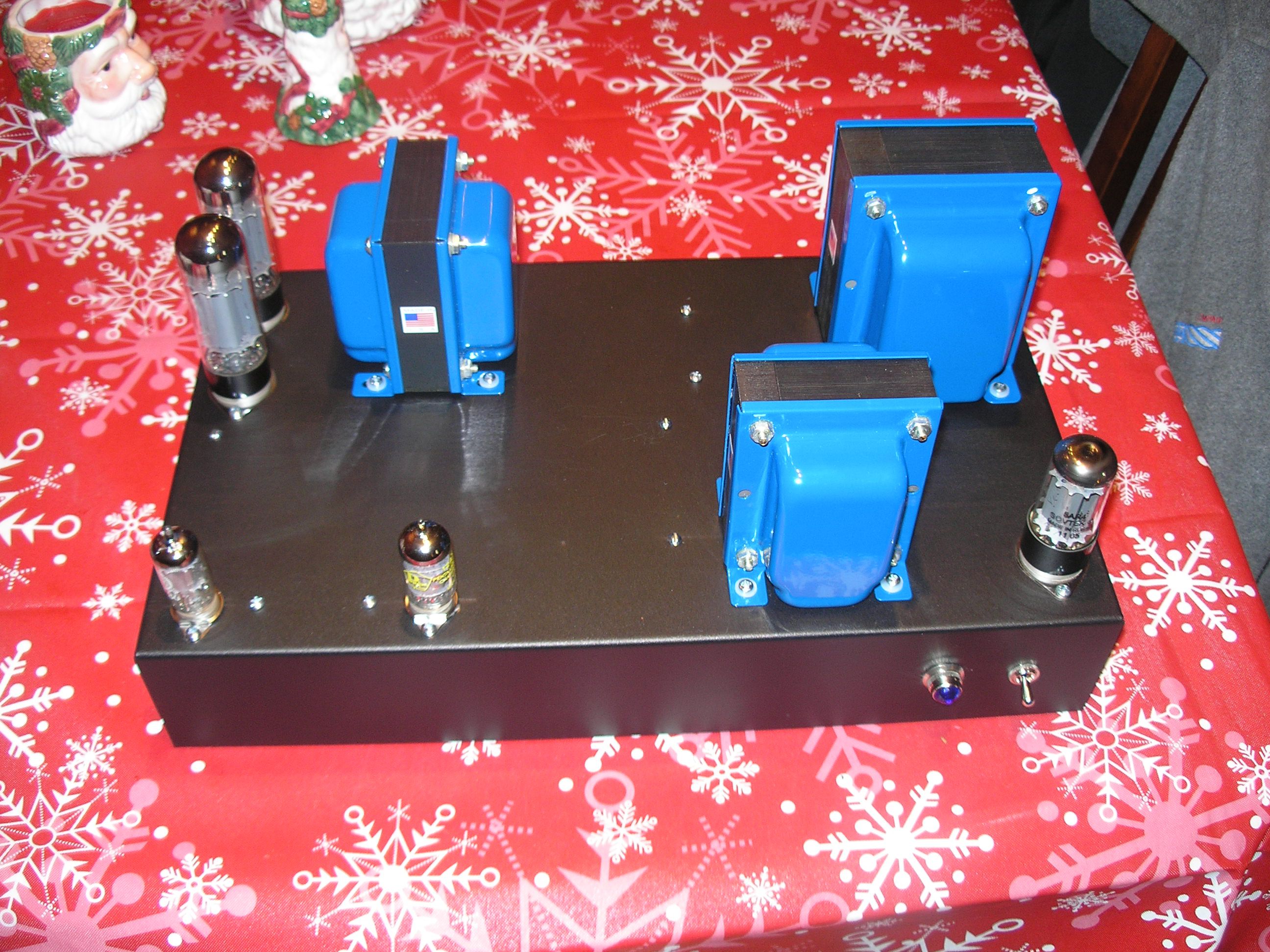
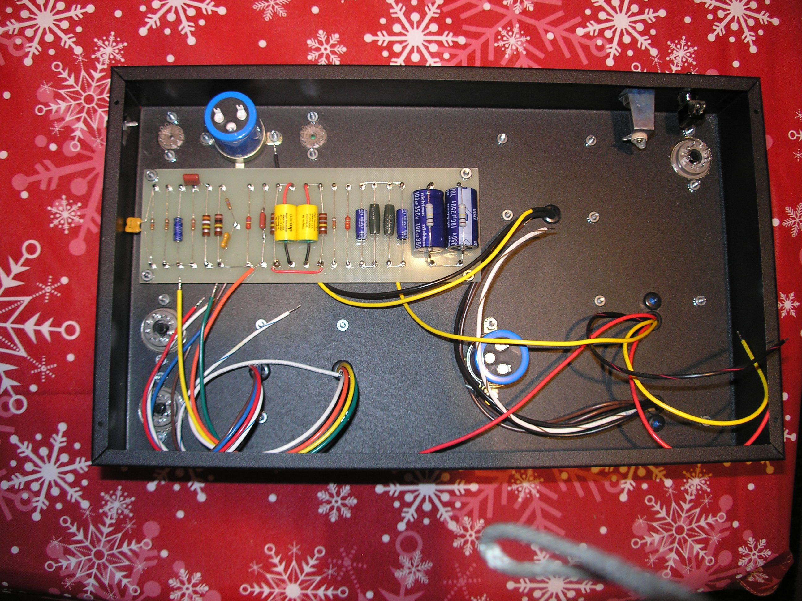
Accomplishments? I am not sure what you are asking. I am not in the business of making amplifiers, I have zero interest in sending an amp off to a reviewer in hopes to get a name out for profit. This is just a hobby for me that I enjoy, once you start to have to put food on the table one needs to focus on business and profit and not just the joy of doing something. I have no accomplishments and admit openly. But that doesn't necessarily mean I don't know what I am talking about. My friend Bruce Egnater from Egnater Amplification (guitar stuff) is very successful I would say but why does he contact me asking questions about how to improve this or that in his gear? For example his latest model is a tube preamplifier and he was trying to improve the signal to noise ratio, he remembered something we had discussed previously so he reached out for some help to which I happily provided. A friend of mine that loves vintage tube gear wanted that type of sound but on his budget. He sadly didn't want anything fun but hey it's his amp, he basically named a few amplifiers he really liked and most were Mullard 5-20 circuits and he loves the EL34 tube. Hey who am I to tell him what he likes. He has Klipsch Cornwall speakers btw. For anyone that knows anything about the Mullard circuit it has way too much gain. So I decided to triode wire the EF86 and instead of using a 12AX7 for a phase inverter I used a 12AY7. This dropped the open loop gain to more acceptable levels but more importantly it also dropped the amount of negative feedback from -30db to around -20db. For anyone that has tried to stabilize -30db or more of feedback around an output transformer and one stage of AC coupling (more phase shift) it isn't for the faint of heart. I was able to increase phase margin substantially by lowering open loop gain and subsequent amount of negative feedback. I gave him the classic layout look inside complete with turret board and multisection capacitors that I typically don't use. I had a very small budget to work with and so they are not the most beautiful amplifiers. The inside picture is not completely wired up and ground bus wasn't installed yet. I am trying to look for a finished picture of the inside but can't seem to find one on my computer. Just an example of budget amplifier that can be made and not break the bank. There is plenty of room for upgrades in the future. He absolutely loves the sound and couldn't be happier. Both mono amps shipped across the country was a total cost of ~$1400. Shipping wasn't cheap either.

-
Great read explaining the genome coding and how they design and produce the treatment. Who wouldn't want a DNA 3d printer right? I have the paper from the University students also. https://mottikumar3.medium.com/reverse-engineering-the-source-code-of-the-biontech-pfizer-sars-cov-2-vaccine-d3503a34f95f
-
I was always very fond of music and musicians gear along with the audio equipment meant to recreate it in our homes. The thought crossed my mind to possibly get into the industry but doing a startup is a shot in the dark and is extremely hit or miss not matter how good your product is. At the time it was just too big a risk and I just wanted to start earning money so I could live a comfortable life instead of going bankrupt. This wasn't a personal decision, I had a family to provide for so I took jobs with financial security. I never stated I am a successful amplifier company, I just enjoy making things especially amplifiers. I know I am in the minority in my viewpoints compared to your average audiophile and when one of them hears something from me they don't want to believe well then this is always how the argument starts. When they don't like the message they character assassinate the messenger to try and discredit me. It's fine, I don't expect to change peoples minds over night.
-
If anyone is interested I have backwards engineered genome code for Pfizer's Mrna Covid vaccine. Not joking, another hobby.
-
Check internal connections of course first. If you do not see anything out of the ordinary with wiring try lifting one leg to the shunt electrolytic capacitor in the woofer circuit. Or you can try jumping out the inductor with a wire effectively bypassing it shortly to see if sound comes though the woofers. I doubt it's the inductor, rarely they fail. My guess is either bad connection or the electrolytic has shorted and is dumping the full signal. There is a possibility especially if you listen to records of a low frequency oscillation that did fry both woofers. I have seen it happen.
-
Basically, don't look at it like 3kHz-8kHz is 0db and the engineer needs to boost 8kHz-20kHz +6db or whatever, look at it as they are reducing the 3kHz-8kHz by -6db and due to filter slope the signal returns to 0db where the driver would have it's low output region, 8kHz-20kHz. Numbers not exact, just an example.
-
It's just how capacitors naturally function in relation to frequency, at lower frequencies where the driver has higher output the impedance of the capacitor is higher giving a signal drop across it effectively reducing the signal to the driver, as frequency increases into the lower output region of the frequency plot the capacitor has decreased it's impedance not giving a drop across it, this naturally flattens the driver plot out. For example the Klipsch AA network has the tweeter down -6db at 5kHz compared to input of the network. This -6db loss across the filter network is reduced as frequency increases.
-
A picture is worth a thousand words. I was curious why in gods name would they even consider DC bias for polypropylene capacitors. The white paper failed to mention they also use bipolar electrolytics which of course has higher dissipation factor and nonlinearities, and where you usually see people using a DC bias. The white paper also states using air core inductors because they don't suffer hysteresis from core saturation. The extra DCR from all the extra copper needed to get the same inductance as regular ferrite core inductor is in my opinion more an issue instead of just sizing the ferrite core inductor high enough to not saturate. I have never been wowed ever when someone has changed a regular core inductor to an air core inductor. IF you can get the same DCR which I highly doubt without it being massive in size yes I can see the advantage but normally I see them about double the DCR which I would think it would matter on how mechanically damped the woofer is and the increased DCR is moot. Either way there are always tradeoffs, I just don't see a huge difference in sound going air core if the regular core was sized adequately. Measurements confirm this. The DC bias now makes sense getting a look at the crossovers, they use cheap electrolytics in their networks.
-
Russian MBGO Paper In Oil Caps
captainbeefheart replied to Racer X's topic in Technical/Restorations
No not at all, well not that I have measured anyway. Audible testing confirms this, to quote RacerX "Compared to the Solens, the Russian PIO caps are louder, more lively, and dynamic. The sound is fuller, has more body." If ESR was high he would have losses especially through the tweeter, it would sound dull and dark, like a blanket covering the speakers. It's the opposite when using these, the sound opens up, cleaner, crisper without fatigue. They just work very well in these speakers. -
The paper states "The UHF control provides similar adjustment from 4 kHz to beyond 20 kHz" The frequency chart of just the driver is with a flat input frequency, the network adjusts levels to compensate for driver inadequacies.
-
They explained in the paper they rectify the AC signal to DC with diodes, same way the electrovoice tweeter protection device creates DC to power the relay to trip. To me the whole DC bias is silly compared to the distortion caused from nonlinear rectifier load. The charge currents might diminish to a very low value once a charge is built up on the capacitors. I just don't see how a polypropylene capacitor with a very low dissipation factor already show any non-linearities around the zero crossing point. I can see the argument if they were using aluminum electrolytic capacitors but polypropylene no. Just marketing BS to sound cutting edge and sell speakers.
-
Russian MBGO Paper In Oil Caps
captainbeefheart replied to Racer X's topic in Technical/Restorations
I have found this statement to be true in my experience. Just imagine if Jensen or any of these other boutique capacitor companies were to manufacture these types of Russian Capacitors to the same exact construction and specifications they would be VERY expensive for them to produce. We just happen to be fortunate enough to have quality surplus Communist military electronic components be sold off to the public. You get a lot for very little money it's amazing. It's also nice many have mounting ears making fastening them to the crossover board very easy. -
Russian MBGO Paper In Oil Caps
captainbeefheart replied to Racer X's topic in Technical/Restorations
I think we all wish he was giving them away for free lol I don't want to divulge too much info but we have been messaging and I recommended those to him as an affordable way to try paper and oil capacitors. I am certain he will come back in and have a full review of them but from what I gathered he was pretty blown away by the improvement they made compared to Solen polypropylene capacitors that were in there. -
Cheap Forum Amp by Captainbeefheart
captainbeefheart replied to MEH Synergy's topic in Talkin' Tubes
Gain is +20db, with 1Vrms input you will reach 12.5 watts output. Another reason why I was going to conservatively rate the amplifier as a 12 watt amplifier, that and distortion is at 1% at 12 watts. People can enjoy the amplifier directly from a source without a preamplifier. From experience with real world grid current drive vs simulation it's tough for me to tell the exact output at 5% THD but I am willing to bet it will be at least 20 watts. It's my experience that the majority of sources will be at least 1Vrms or 1.4Vpeak which means those will never clip the amp, and of course many sources especially today's high end CD players or DAC's use higher rail voltages for the opamps, usually at least +/- 5V easily outputting 2Vrms and of course if you use a preamp on average they can swing even greater output pushing the amps boundaries to maximum of around 20 watts. 1.26Vrms will get you to 20 watts which should be doable from most sources. -
Cheap Forum Amp by Captainbeefheart
captainbeefheart replied to MEH Synergy's topic in Talkin' Tubes
I will have to check to see if I have some around to try. The 6BX7 is great for common cathode stage with the output at the plate due to the very low plate impedance, like with a Williamson circuit driving the power tubes. For a follower stage it doesn't gain much in regard to transconductance vs 6SN7 which will determine cathode impedance. I have several very high gm tubes that I have experimented with followers but some have stability issues. One such tube is a 12HL7 which doubles the gm of a 6BQ5 at 21mA/V or 21,000uMhos. That can give us a follower stage with an output impedance of 47 ohms!! The 6BQ5 works pretty good with an output impedance around 100 ohms, it is still in production which is also a bonus. When I build this circuit I will be able to see the grid drive performance better vs simulation as the models don't really work great for grid current. If the 6BQ5 is much better vs 6SN7 parallel which will have similar gm I will go with it. -
Cheap Forum Amp by Captainbeefheart
captainbeefheart replied to MEH Synergy's topic in Talkin' Tubes
For a hoot I tried an EL84 triode strapped as the follower circuit instead of the 6SN7, it does gain some power. 17.3 watts output at 5% THD. Not a huge ordeal, just need to make the power supply a little more beefy for the extra current. FWIW These models aren't great at accuracy for grid current A2 mode. It's ballpark enough and extremely accurate for non grid current operation but from what I have measured in reality is always much better. It will most likely be 20 watts or more at 5% THD. -
Cheap Forum Amp by Captainbeefheart
captainbeefheart replied to MEH Synergy's topic in Talkin' Tubes
Another idea is to add another bottle for 6 total, each channel gets a whole 6SN7 and tie both triodes in parallel, run it at 20mA with a low value cathode resistor. -
Cheap Forum Amp by Captainbeefheart
captainbeefheart replied to MEH Synergy's topic in Talkin' Tubes
It depends what value R6 is, the design is tolerant to 4.7k-82k. The lower the value the more current it can deliver, it will maintain signal integrity better past 0v so more power out. For someone that will not push the amplifier at all I'd install a 47k-56k for long life. Real world testing I'll decide which gives best performance at as low a value as I can get, might be 22k-39k my guess but if 56k (1.6mA) works well enough I'll leave it. For someone that wants ultimate full power performance to squeak every bit out of it 10k will do well (8mA) or possibly lower, maximum I would run idle is 12mA. -
Cheap Forum Amp by Captainbeefheart
captainbeefheart replied to MEH Synergy's topic in Talkin' Tubes
I have thick skin.........don't worry my feelings will not be hurt lol. Should I submit a couple different ideas along with this? That's no issue at all, I am more than happy to model several ideas before I start building. I have lots of parts to whip up a channel and test it as soon as we get a design approval from the committee, that's you Or do people not really give a crap about details and have me make an amp, take some measurements and pictures and put it up as the first prototype? I like an organic process, no need to be confined to strict protocols. -
Cheap Forum Amp by Captainbeefheart
captainbeefheart replied to MEH Synergy's topic in Talkin' Tubes
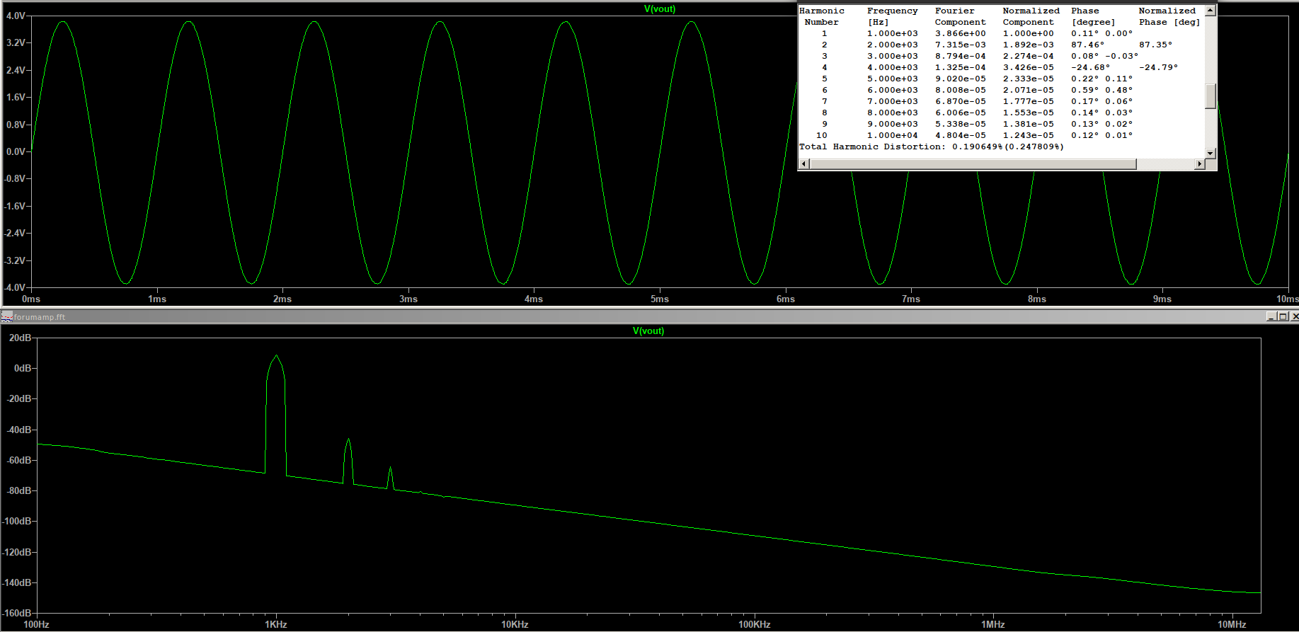
1 watt output .19% THD Clean and accurate but with a little second harmonic dominant distortion and blip of third. This or even lower is where most of us Klipsch users will be running on average listening.
-
Cheap Forum Amp by Captainbeefheart
captainbeefheart replied to MEH Synergy's topic in Talkin' Tubes
Typical output distortion profile I aim for in a single ended amplifier, second harmonic dominant and then the cascading 'waterfall' look of diminishing harmonics. I'll post at 1 watt. -
Cheap Forum Amp by Captainbeefheart
captainbeefheart replied to MEH Synergy's topic in Talkin' Tubes
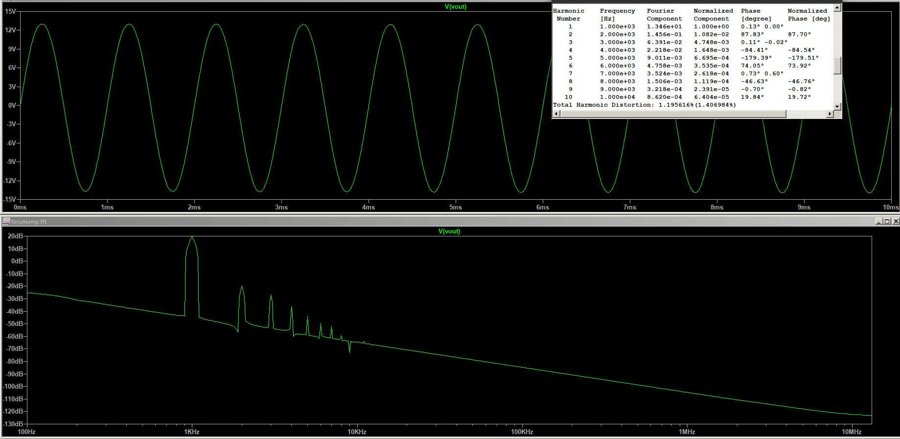
12 watts output 1.19% THD
-
Cheap Forum Amp by Captainbeefheart
captainbeefheart replied to MEH Synergy's topic in Talkin' Tubes
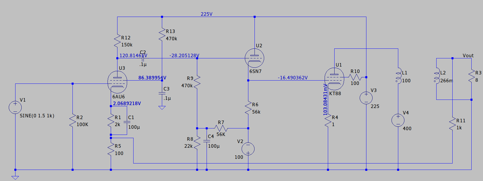
Here is a stripped down schematic, just the signal circuit excluding the variable damping control. 12 watts 1% THD it will push more power out but at higher distortion. I conservatively rate my amplifiers. Fixed resistors in the bias scheme will be changed to a pot for adjustment in the build. The 1 ohm cathode resistor will either have tip jacks going external for bias readings, or I will install a current meter in the cathode circuit so nobody needs a digital volt meter to change bias. Whichever people feel is best and if I can add the analog current meters for decent cost. There are no compensation networks at this time, I do that after it's built. 6SN7 may be changed to 12AU7 or 12BH7, anything similar. Same for 6AU6A, will try different small signal pentodes once built. Thoughts? Ideas?
-
The major reason I still have La Scala's is the room. I have heard K-horns both done properly in a proper room and I have heard them with people that have a not so ideal room for them and tried making it work. They were happy with the sound and I didn't want to be negative but they didn't sound as they should have. I knew then that unless I have an ideal room with corners without windows near by where the ideal sweet spot can fit a nice comfy couch I won't get K-horns. It's still a goal of mine, I want to die with k-horns so I will get there but for now my La Scala's are more than sufficient for amazing sound. I do have a 2.1 system with a sub-woofer.