mboxler
-
Posts
574 -
Joined
-
Last visited
Content Type
Forums
Events
Gallery
Everything posted by mboxler
-
what is the best crossover frequ for la Scala clone ?
mboxler replied to SpeedLimit's topic in 2-Channel Home Audio
I believe you meant to say "at most" 100 ohms in line with the tweeter. When low current is passing through the circuit, the switch is low resistance (0 ohms?), and all the current is flowing through the switch and tweeter. 0 ohms in parallel with 100 ohms is 0 ohms. If too much current is flowing through the switch, it's resistance increases, and current begins to flow through the resistor as well. This continues until the switch can cool. Until then, there is a voltage drop across the switch//resistor, and therefore less voltage across the tweeter. -
Sorry...I meant tweeter. Your DE10-8 can handle 40 watts, so if I were you I'd replace the K-77 protection circuit with a wire. Mike
-
The K-55M is an EV 16 ohm driver. As I understand it your Atlas is identical to the K-55V and K-55X. I think the rde 050 is a poly switch, and it should be 0 ohms(?). If it's functioning properly, 0 ohms in parallel with 100 ohms is still 0 ohms. If it's broken, then yes the signal is now passing through a 100 ohm resistor, greatly reducing the voltage to the squawker. Sorry, when you said it wasn't right I didn't realize you meant inaudible. Can you measure the resistance across the 100 ohm resistor? If the switch is okay then it should measure 0 ohms. If it measures 100 ohms you found your problem.
-
You may have a couple of things going on. The AL-3 was designed for the K-55M, which is a little hotter than the Altas. I think that's why the AL-3 uses the T4A autoformer. It looks like the DE10-8 has 107 dB sensitivity, as opposed to the K-77's 104 dB. I wonder if it would sound better if you pad down the DE10-8 3-4 dB? The AL-3's high pass filter is designed for an 8 ohm load. A 16 ohm load kinda messes up the elliptical-shaped voltage. Mike
-
While toying around with filters, and stumbled upon something, though I doubt it's anything new. It pretty much eliminates the 8kHz bump on my K-55M drivers (K-400 horns). The prototype consisted of three components. A series 330uh inductor followed by a 400uh/1uf series notch filter to common. It sits between the crossover's squawker out terminals and the K-55M. Attached are sweeps of the K-55M in series with a 24uf capacitor. Talk about an extreme slope! The "M-Trap" creates a fairly steady drop from 5850Hz to 11000Hz. I know a P-trap has been used to reduce the bump. Others say the bump is not audible. Unfortunately, I only have ALK crossovers, so I can't comment either way. Still, I thought I'd share my find. Apologies to anyone who already tried this. Mike

-
One of the original owners may have done this on purpose. If it truly has Type E component values, the squawker and tweeter levels will be down 3dB each, and crossed at a slightly higher frequency vs a type B. In other words, an increase in bass. As @RandyH000 mentioned, converting it back to a B requires one capacitor change and two autoformer tap changes. If you are handy with a soldering iron this is a relatively easy project, but I'd fix the other issues first. You may like the sound of the Type E better than the Type B!
-
The Type E crossover was designed for the Heresy, not the Cornwall. I believe the 76 Cornwall should have the Type B (?). Do both speakers have the same crossover type? Pictures will help. Do you have a multimeter to check if the tweeter is okay?
-
Hi The HUGH capacitors inside the woofer door are for the woofer only. Are you planning on keeping the 140 uf values (AK-2) or replacing them with 100 uf caps (AK-3). As you may know, the AK-3 changed the autotransformer and squawker shunt inductor values as well. On to bi-wiring. The fuse for the high frequency current (1 1/4 amp) is located in the door, and is wired between the low pass + and the high pass + speaker terminals. If you don't care about a fuse, then simply run the first wire to the woofer in + and - on the woofer door and the second to the top hat crossover input + and -. If you want to keep a fuse. it would be easiest to just add another one in the top hat before the high pass crossover. Mike
-
Capacitor Rabbit Hole. Just How Do You Measure?
mboxler replied to Dave A's topic in Technical/Restorations
What do others think about electrolytics, like the 33uf ones that come with E2 crossovers? They don't particularly measure well, but I assume Klipsch was okay with that. I always thought that the AK series crossovers were designed to make up for the lower SPL of the K-33-M in the 300-500 Hz range. The large capacitor across the K-33 and the large inductor across the squawker result in voltage bumps in that area to compensate. Getting back to capacitors. I have K-55-M's, and I always thought there was something missing when using my hybrid crossovers (2.4mH inductors to the woofers). I had a couple of cheap 15uF electrolytics, so I added them across the woofer terminals. I'm probably hearing things, but this seemed to fill in that "hole". I didn't try larger values, but the larger the value the greater the "bump". If anyone is a tweaker as I am, try this. I'd be curious if you notice a nice difference as well. Mike -
I would think that the impedance of a K33 in a Cornwall would be closer to 6 ohms (?). A 2.5 mH inductor is 6 ohms around 380 Hz. I assume you are referring to the Type B crossover? The 20uF capacitor across the woofer (Type B2) will extend the -3dB point to around 500 Hz, but it drops off twice as fast after that. If you have a B, try the capacitor. You may have to reverse the squawker polarity. Also be aware that the addition of the capacitor will boost the upper bass, but you may find that pleasing to your ears. Mike
-
Looking for some help with AA crossovers..
mboxler replied to Dudeisms's topic in Technical/Restorations
Here's a possible recipe! This will give you roughly a 3rd order Butterworth high pass to the tweeter around 4500Hz and a first order low pass to the squawker around 4500Hz as well. I changed John's schematic (thanks John!) to show the new ingredients. I don't have an AA crossover to test, however. I agree with moving the tweeter filter away from tap 5 as it creates a series connection with the main high pass capacitor. Add 500uH inductor between T2A and squawker. Add 1uF capacitor in parallel with first 2uF capacitor to get a 3uF capacitor. Add 6.8uF capacitor in parallel with second 2uF capacitor to get a 8.8uF capacitor. I'd leave the 245uH inductor alone. The ideal 210uH inductor will not make that much of a difference. You are right! I believe this will work, but I always reserve the right to be wrong. Mike
-
Perhaps a little off topic, but... As I understand it, Klipsch went from the AA tweeter filter to the AK tweeter filter (elliptical) to further protect the K-77. It's much steeper slope eliminated the need for the zener diode. Was this a cost saving modification? Also, I hardly ever see discussions about this high pass elliptic filter. Is it considered poor sounding? Thanks, Mike
-
Nice! I, too, am working on my Type E2 crossovers. First I'll try adding a p-trap to the squawker to try to tame the massive hump around 10.5 kHz. Hopefully that will reduce some of the top-end brightness. Mike
-
I didn't notice, but you are right. Move squawker from 2 to 1, tweeter from 3 to 2. That will attenuate both by an extra 3db.
-
The electrolytic is fine, since it is in a shunt position across the woofer. I'm sure it's a lot smaller too!
-
No matter what you do, the impedance curve will never be flat. If your amp worked okay driving the stock Heresy using the 8 ohm outputs then it should be fine with the 20uf cap and 12 ohm resistor. Oh. I assume the 33uf capacitor is the original electrolytic bipolar. At 35 years old it's probably time to replace. Mike
-
If you want to get to around 8 ohm, you would need a 9 ohm resistor across taps 0 - 5 and larger capacitors (around 27 uf). Unless you really want an 8 ohm load, I'd stay with the 20uf cap and 12 ohm resistor you have and see how you like it. Mike
-
The difference between the two approaches is the load on the amp. If you look at a Heresy impedance curve, it soars to 72 ohms. If that's okay, than the 15 ohm resistor across the squawker (and I'd add an 8 ohm across the tweeter as well) will keep that same curve. The 21uf cap/11 ohm resistor method will lower that curve to around 10 ohms...a flatter curve. The 20uf cap and 12 ohm resistor you have should work just fine. The impedance curve will flatten to around 11 ohms, so a lower value capacitor would be needed anyway. Mike
-
Yes...works with E or E-2 Yep. No, the 15 ohm resistor should not be added if you are going with the 11 ohm shunt resistor/21uf primary cap. Mike
-
K-52-H Impedance Plot - Something Wrong?
mboxler replied to mboxler's topic in Technical/Restorations
That may be my best option. My idea requires the squawker low pass AND the tweeter high pass components to be AFTER the autoformer. The weird impedance of the K-52-H may make that difficult. Learning a lot about elliptical filter design though 🙂. -
K-52-H Impedance Plot - Something Wrong?
mboxler replied to mboxler's topic in Technical/Restorations
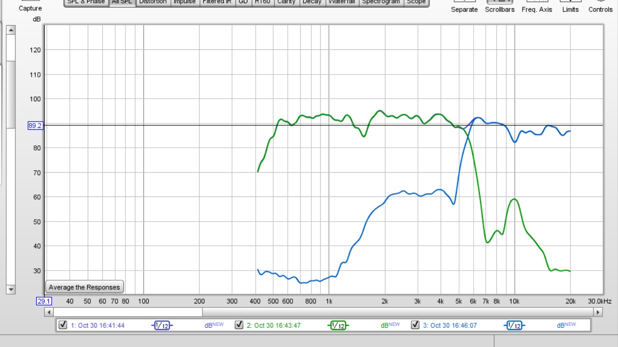
Right now I'm using ES5800T crossovers from ALK to see what a "professional" plot would look like. I can only attenuate the squawker, so I adjusted it to get to the CT-125 level. If I had a tweeter attenuator, I could actually listen to the speaker. The crossover I'm designing will allow variable attenuation of both the squawker and tweeter to get them both down to the Heresy's woofer level. Mike -
K-52-H Impedance Plot - Something Wrong?
mboxler replied to mboxler's topic in Technical/Restorations
Thanks! Today I ran the same test on the other K-52-H, and got more symmetric plot. I'll assume all is okay. Mike
-
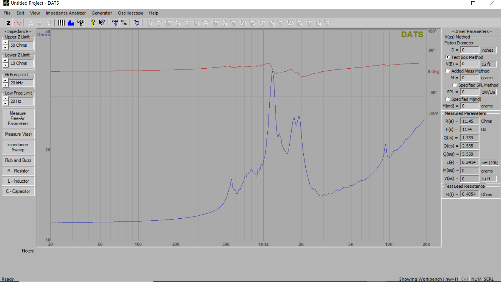
I'm playing around with extreme slope crossovers in one of my Heresy I's, and noticed a large dip in the frequency plot around 1600 Hz. I just received a DATS V3 box, and ran a test on the K-52-H/K700. What the heck is going on between 1Khz and 2Khz? Would this cause the dip on the plot? Thanks, Mike
-
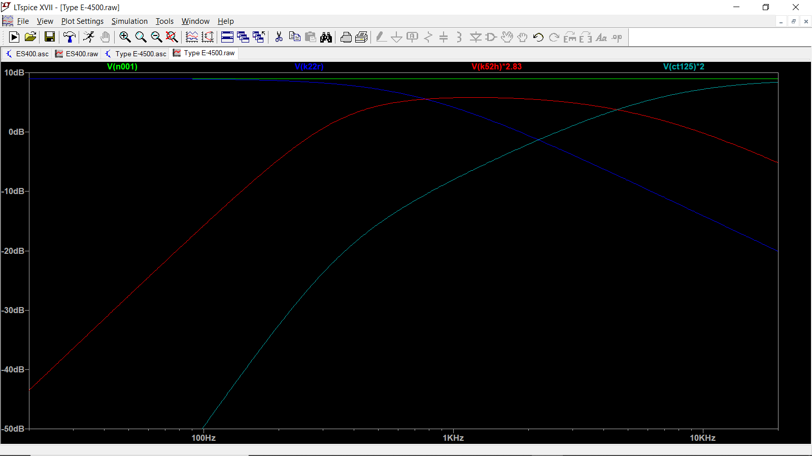
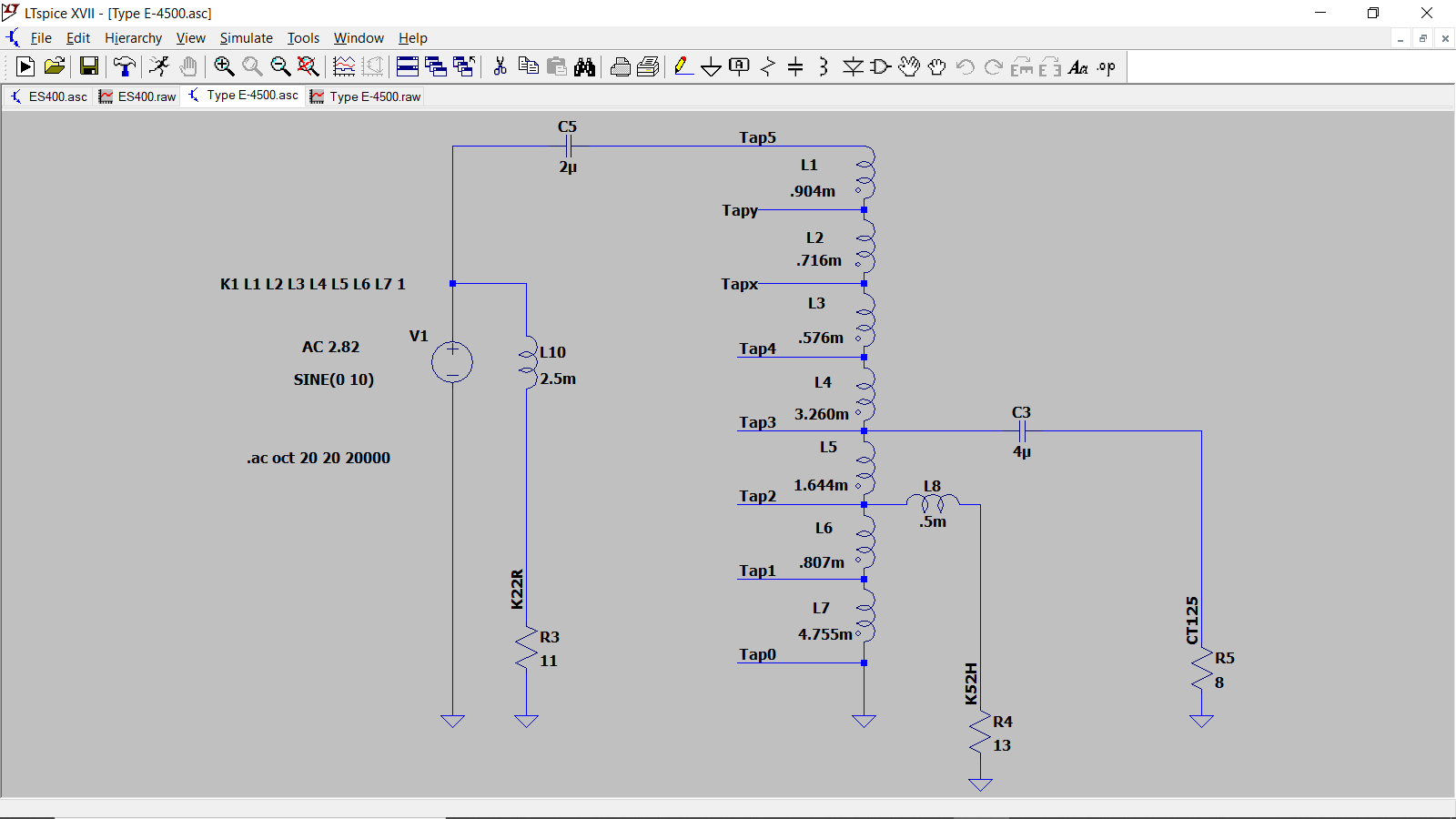
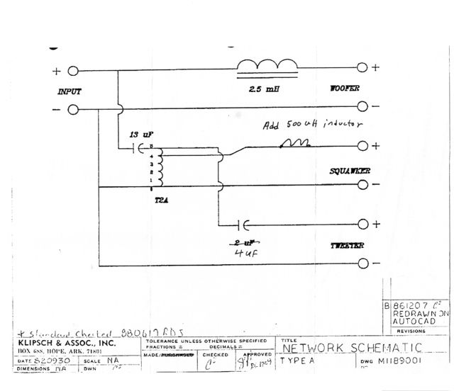
Sorry for the confusion. I thought you were interested in a change similar to Bob Crite's A-4500. I'm assuming the components to change a Type A to a Type A-4500 would be identical to the ones needed to change a Type E to a Type E-4500. So, add the .5mH coil to the K-55 leg and replace the 2uF tweeter capacitor with a 4uF. Again, I haven't tried this. Here's the schematic and resulting plot. I'm a "If it sounds good it's right" guy, so experiment. Add the coil first, and hear how it sounds. Add 1uF to the tweeter cap (3uF). Add 2uF to the tweeter cap (4uF). Let us know what sounds best to you! Mike
-
You mean this?