Alexander
-
Posts
1364 -
Joined
-
Last visited
-
Days Won
1
Content Type
Forums
Events
Gallery
Everything posted by Alexander
-
ALK xover - DIY for Forte II schematic
Alexander replied to Alexander's topic in Technical/Restorations
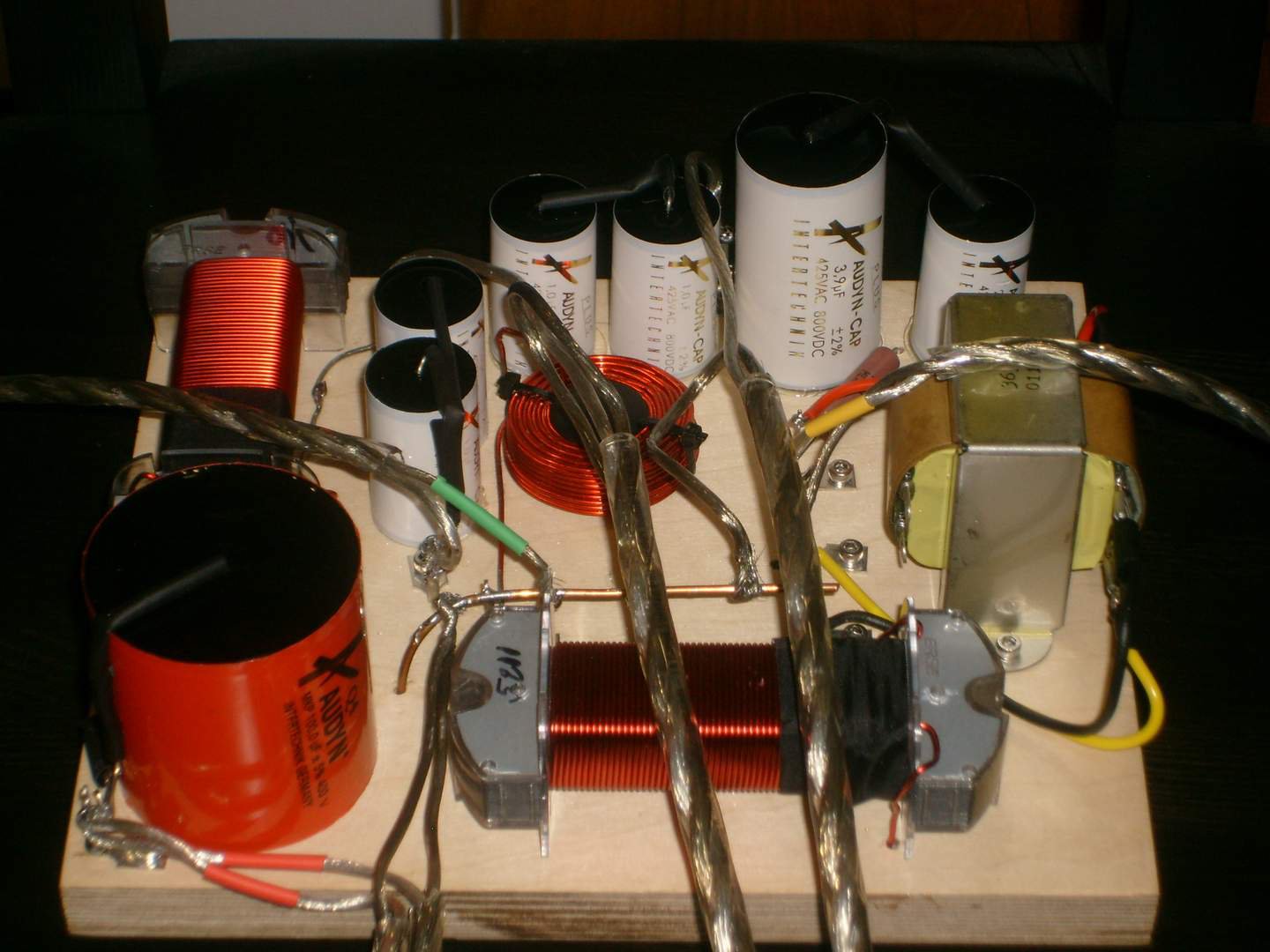
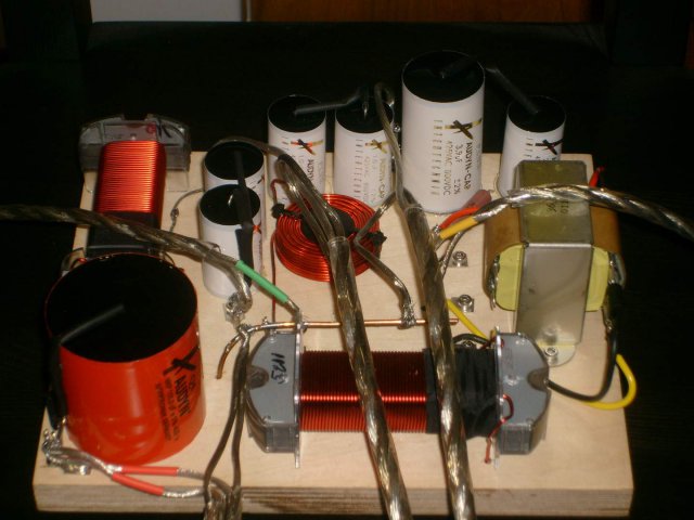
Here is the pic I promised you. The #14 red & black wire in the center are from the binding posts, #16 red & black are the woofer, #16 yellow & black are for the mid and finally the green & black are to the tweeter.
-
ALK xover - DIY for Forte II schematic
Alexander replied to Alexander's topic in Technical/Restorations
dup -
Where to find crossover connection posts
Alexander replied to jimjimbo's topic in Technical/Restorations
I can relate to that -
Where to find crossover connection posts
Alexander replied to jimjimbo's topic in Technical/Restorations
That is why I did it this way on my project. -
ALK xover - DIY for Forte II schematic
Alexander replied to Alexander's topic in Technical/Restorations
Thanks, and will check out the thread - always willing to learn... -
ALK xover - DIY for Forte II schematic
Alexander replied to Alexander's topic in Technical/Restorations
Deang wrote: On many of those connections, it doesn't look like you have enough room to put a clip/heat sink between your part and your ring tongue. I don't understand the point of crimping and soldering, yet stacking the ring tongues together and screwing them down - which will allow air and moisture to creep in (you strive for a gas-less connection, but really won't have a gas-less connection). Just random thoughts from the peanut gallery - sorry! Thanks Dean for your input, you are way out of league it is not even funny. The few resistors are too short as you pointed out but were measured before and after with no change in values. All of the remaining components have enough to clip on a heat sink and was used. Curious how much free oxygen & moisture is in a non ported enclosure (Forte II)? Suppose one could seal the terminals once assembled to address that possibility. The method chosen was so it could be modular, with any single component being able to be replaced for future evaluation since the budget dictated using things like Solen caps, Lynk resistors and the like. I did go with stainless steel hardware though. Note: Deang I copied your post from jimjimbo's thread as to not hijack it. -
ALK xover - DIY for Forte II schematic
Alexander replied to Alexander's topic in Technical/Restorations
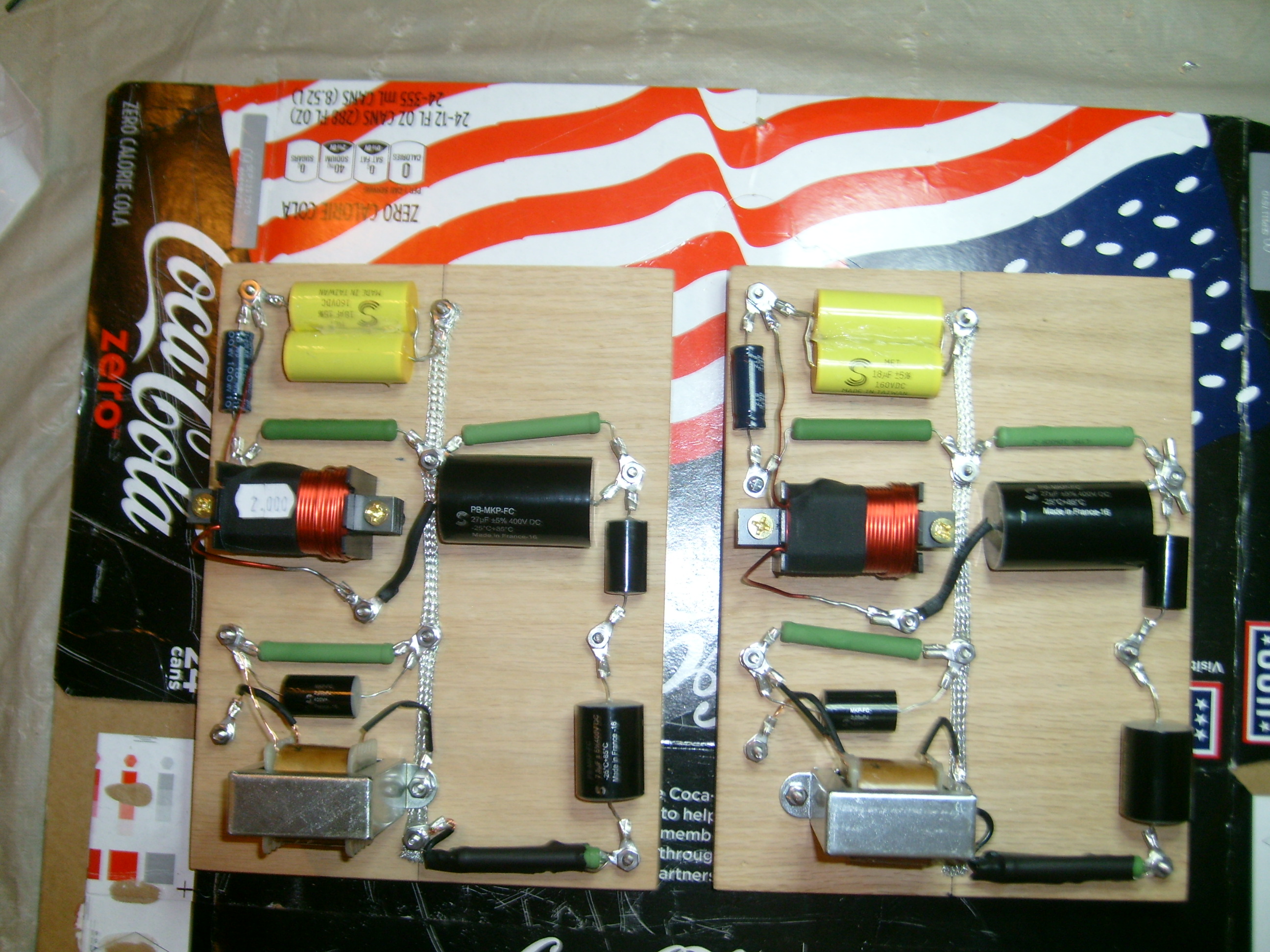
Both boards are fitted, now to take them apart and solder all the crimps. Sure hope the bar solder shows up soon so we can tin the coils and finish this project. These things are looking better than I had thought but by no means a work of art compared to the stuff ALK has put out.
-
Where to find crossover connection posts
Alexander replied to jimjimbo's topic in Technical/Restorations
I used regular #6 1.25" machine screws for a 3/4" board as you see in my picture. I got them at Lowe's btw. -
ALK xover - DIY for Forte II schematic
Alexander replied to Alexander's topic in Technical/Restorations
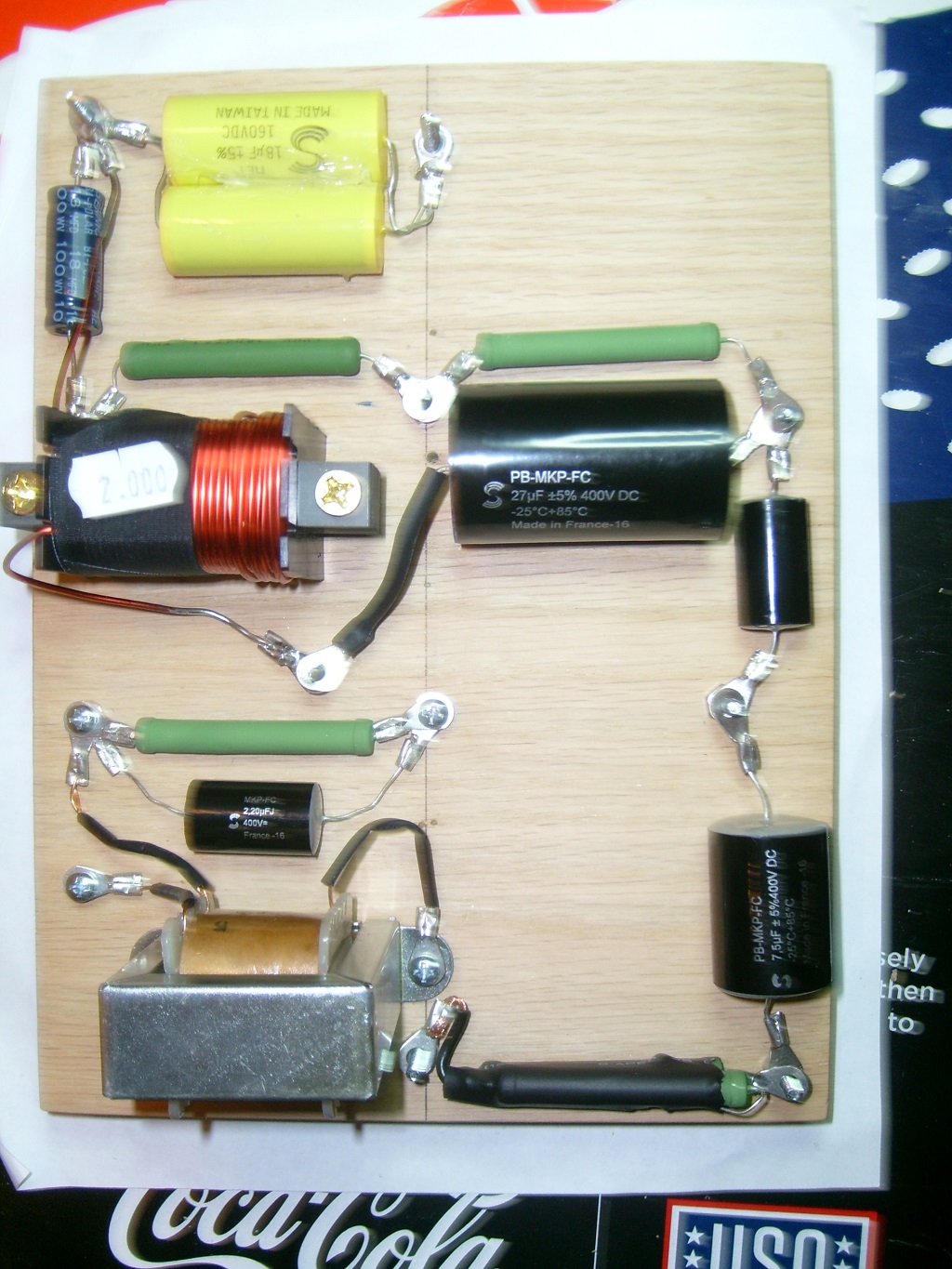
Here is one board mostly fitted, just need to do the soldering. Still waiting on some bar solder for the solder pot. And yes I see I have wires # 2 & 5 reversed on the autotransformer.
-
ALK xover - DIY for Forte II schematic
Alexander replied to Alexander's topic in Technical/Restorations
None are needed, we will have a pic put up to show how it all is connected when finished. -
Not to take anything away from this site but they sell factory refurbished units and not brand new should that matter to you.
-
Marantz & Denon (D-M) are bed fellows, some may argue that the Marantz is better than it's Denon brother but generally you will pay more for it. I have the AVR-X3200W and have nothing but positive results with it. As for cables there is a lot of voodoo and smoke & mirrors, check out the link in my sig bellow before you spend your money on cables.
-
give this youtube video a try:
-
ALK xover - DIY for Forte II schematic
Alexander replied to Alexander's topic in Technical/Restorations
No Mills here, just Lynk. At least we are not using sand cast anyway. -
ALK xover - DIY for Forte II schematic
Alexander replied to Alexander's topic in Technical/Restorations
Must be Karma getting me back -
ALK xover - DIY for Forte II schematic
Alexander replied to Alexander's topic in Technical/Restorations
ARRRG!!! I just realized I ordered 3.9 ohm resistors and not 39 ohm. I do have some Lynk 40 ohm 5% (2x20 ohm) and that will work, if I were to use 10% tolerance 39 ohm I would be in the same range. Need to get a new 9v battery for the DVM to see how close we are - just can't let it go. -
ALK xover - DIY for Forte II schematic
Alexander replied to Alexander's topic in Technical/Restorations
I have a solder pot I guess I could make a video but it might be a bit boring -
ALK xover - DIY for Forte II schematic
Alexander replied to Alexander's topic in Technical/Restorations
At some point I guess I can put my .02 cents. -
ALK xover - DIY for Forte II schematic
Alexander replied to Alexander's topic in Technical/Restorations
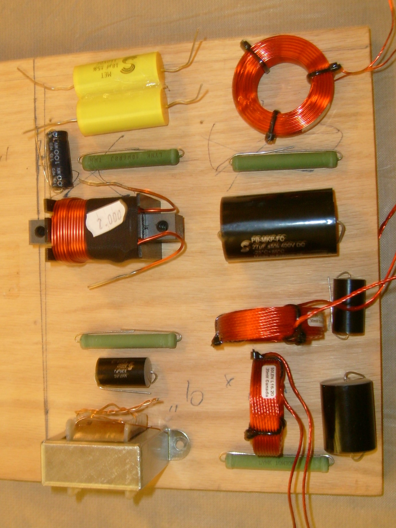
here is a mockup
-
ALK xover - DIY for Forte II schematic
Alexander replied to Alexander's topic in Technical/Restorations
All of the components are in, now all I need now is to get the board(s) cut to 7x9 - or something fairly close anyway and the build will begin. -
I had Speaker Exchange do both passives in my Forte II's for $107 total about two months ago. I was local to the area (Tampa, FL) so it was a pickup. http://reconingspeakers.com/
-
Looking for suggestions on replacement woofer on RF7
Alexander replied to Brett J's topic in Technical/Restorations
You mentioned Speaker Exchange (Tampa FL?), have you thought of them to re-cone your damaged driver? They have been doing this for many years. -
found this
-
You may want to also consider the KLF-C7
-
A steal of a deal for someone