captainbeefheart
-
Posts
1422 -
Joined
-
Last visited
Content Type
Forums
Events
Gallery
Everything posted by captainbeefheart
-
The main problem with receivers is they make compromises in performance to put everything into one neat little package. This is why you see so many serious audiophiles going to a modular approach where everything in the signal chain is separate. The latter has the flexibility to quickly swap out any "section" for improvement or analysis. For example we know the phono stages are extremely sensitive gain stages, it needs to take a very small signal (on average 5mV for MM and much less for MC) and bring it up to line level ~1-2Vrms. With a separate phono amplifier you can usually achieve better signal to noise figures for example without having large EMF fields nearby via the power amplifier being such close proximity to sensitive circuitry. Or the large current changes from the power amplifier section may modulate shared signal grounds etc... Having a modular system has the advantage because you can easily swap in and out different sections of the signal chain and with an all in one receiver you are stuck with everything you get. Want a different type of power amp? You can do that and keep your AM/FM tuner, preamps, etc.. and just swap out the power amps. The only advantage to having an all in one receive is just that, it's all in one tidy little package, but it's a compromise much like everything else. This is why I highly recommend anyone serious about music reproduction to go modular. Home theater is different, I too have home theater receivers just for that purpose and they work great for that application. My living room system is an old Sherwood receiver and it sounds great but it doesn't compare to my serious system comprised of modular components. I like the separate power amps especially because I can place each mono power amp very close to the speakers for an extremely low resistance speaker cable of only 16 inches. This makes the variables in speaker cable (mainly resistance) have next to zero impact of the performance.
-
Sorry you felt this way. I have noticed that although the internet and text messaging are great it also does not reflect the users tone and body language. Nobody is ever going to 100% agree with one another, there were many times in my life where we had several engineers and we all had different solutions. Or, maybe two would agree on a solution while the other was feeling like he was being ignored, get frustrated and leave in anger. The bottom line is it's science, we are trying to solve the same issues, we all have that in common. In no way am I trying to tell anyone how to go about doing anything. For example I loved seeing a zobel network on your 1200Hz crossover network, great solution to a problem. I am not trying to tell someone to not use a film capacitor, I am only saying it most likely will exacerbate the resonant frequency issue. I think we are all here to do the same thing, to help and improve the sounds we love so much especially with Klipsch speakers that we also love so much. I apologize to anyone if I came across as being a know it all, I don't know it all and I am still learning every day. I just want to help really.
-
I will try my best to explain the concepts better for people interested. The statement I made about all the important stuff happens at the crossover frequencies is what I will go into depth about as phase seems to be the tough subject in relating electrical crossover properties to acoustic properties. The problem rears it's ugly head near the crossover frequencies because this is where you will have two drivers in the speaker system contributing to the total acoustical output we hear. Around the crossover frequencies is where you will have the largest phase shifts and it's during transients where the phase alignment causes acoustic alignment problems. Because of the phase shift between two signals each driver will reach it's peak excursion at different times. For proper pulse wave transient response you want the signals reaching your ears at the same time, not different times. You can see if each driver reaches each peak at different times then the acoustic signals will not reach your ears at the same time. Let's add some numbers for fun. At 1kHz it takes about .001 seconds to travel 12 inches. One way to resolve this is to physically adjust the alignment of the drivers until their acoustic centers are in alignment. Or you can use electronic phase delay for alignment. This is by far the hardest thing to get right in a multi driver speaker design and why many people have gone to full range single driver systems. Great speakers have coherent sound staging by having good time alignment between the different drivers. The further you get away from the crossover frequencies you are back to just the drivers own acoustic response and the crossover has little to no phase shift issues causing time alignment problems. Hope this makes phase a little easier to digest for the lurkers reading and not contributing, heck even the contributing members may learn something
-
The Audio Impact of Solar Panels and Battery Backup
captainbeefheart replied to Edgar's topic in Technical/Restorations
Even from a perfect "Battery" DC supply you are still at the mercy of noise from currents through active components to even simple resistors. -
For my work I rely on simulations a lot before going into prototype phase. For me it starts with an idea and scribbles with pencils and paper, circuits and calculations. Next thing to do is simulation to check calculations and also fine tune the performance. The prototype phase helps us improve my simulation phase also as if something needs to be moved on the board I need to either input or change parasitic properties into the simulation. Besides designing and building things to put food on the table I have been making radios, amplifiers, TV's, speakers, crossovers, and many other electronic devices for the past 50-60 years. Of course the listening aspect of this hobby is an important one and specs often don't tell the complete story, they can tell you a lot but after making something it always comes down to the listening test, I think we can all agree on that. As for simulations, they are only as good as the models you are using. Use a wrong model you end up with the wrong results, so it's important to know what the equivalent circuit is in order to model accurately. As for this specific scenario, I don't see the purpose of any listening test. We are all on the same page that the acoustic response is the end goal but I feel many have lost sight of how this discussion got started. My original response was to folks choosing to use a film capacitor in the woofer circuit. The original design uses a general purpose electrolytic which has a much higher loss angle and subsequent much higher ESR. This extra resistance in that specific part of the circuit flattens the resonance out and so when changing to a film capacitor one may have to add the extra resistance in themselves to keep the electrical properties flat and more so keep the acoustic properties of the speaker the same as intended. In cases such as yourself you actually preferred the difference in sound so you liked the change in electrical properties and subsequent acoustic properties. The discussion evolved into someone questioning the accuracy of the simulation without the voice coil reactance. Good question, crunching numbers tells us the average voice coil inductance really isn't going to have much reactance at frequencies below 500Hz but people were still concerned so I put the voice coil inductance into the simulation and voila no discernible difference as expected. It is a very simple exercise, inductors and their properties are quite well known and simply calculated but people are visual learners and all of us in here are not electrical engineers so it makes sense to post the two simulations showing the change with and without the inductance. If you find anything wrong with the simulation I am happy to rectify it, if one thinks the T/S parameters will make a difference I can calculate them into an RLC network and add it to the simulation but it should have no bearing on the series inductance and it's effects on frequency response. The simulation is only there to work out the electrical properties of the crossover network, not to be the end game acoustic sound form the speaker as once the crossover is worked out then move onto the measuring acoustic properties of the speaker system as a whole and critique it.
-
Carver Crimson 275 - Has anyone heard one?
captainbeefheart replied to pzannucci's topic in Talkin' Tubes
Wow that meme is too much How are you so certain they both are Carverfest clones and not production models? I can see the one that's a little rough but the signed one looks every bit the part of the production ones in every detail. I looked at part selections on boards, wiring, hardware, everything and it appears a real one. The facts of the matter though are others have maybe not measured them but have taken the covers off to find the same 15 watt transformers. And not forgetting we do have the known fact it only weighs 19 pounds. I get it when people doubted his coffee tin amp putting out double the power of the McIntosh and half the distortion but a pure transformer coupled power amp wanting to put out 75 watts per channel down to 20Hz just cannot happen at the published weight, as stated it's physics. For example just looking at a few different manufacturers of high quality Audio output transformers you would need on average a 12 pound output transformer to get to rated power at rated bandwidth. That's 24 pounds in just output transformers alone. The only possibility is a hybrid output stage with transistors and tubes to meet rated specs but I am sure that would be as disappointing or more so than just having lower output power than advertised. I know this isn't the case because you cannot see an of that circuitry from any pictures and I am certain the tech would have picked up on that immediately. Besides that it would have probably measured a lot better with a hybrid topology. As we all know power and distortion do not equate to great sound. From the reviews it seems to be a very nice sounding amplifier and that's all that really matters. This is just one of those things that is interesting and everybody likes a good mystery. Many people are interested in how this turns out and really in the end it's just one of those things where the company fudged the specs, not the first time it's happened and won't be the last. -
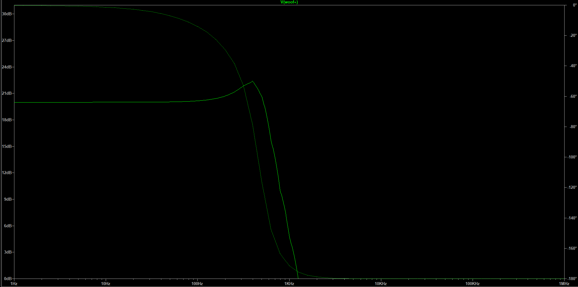
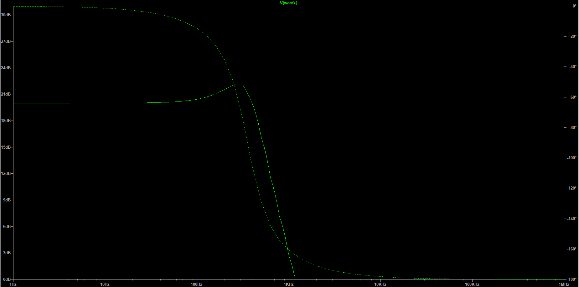
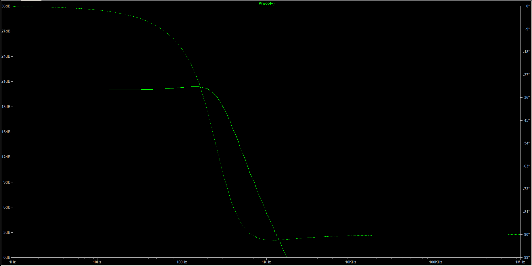
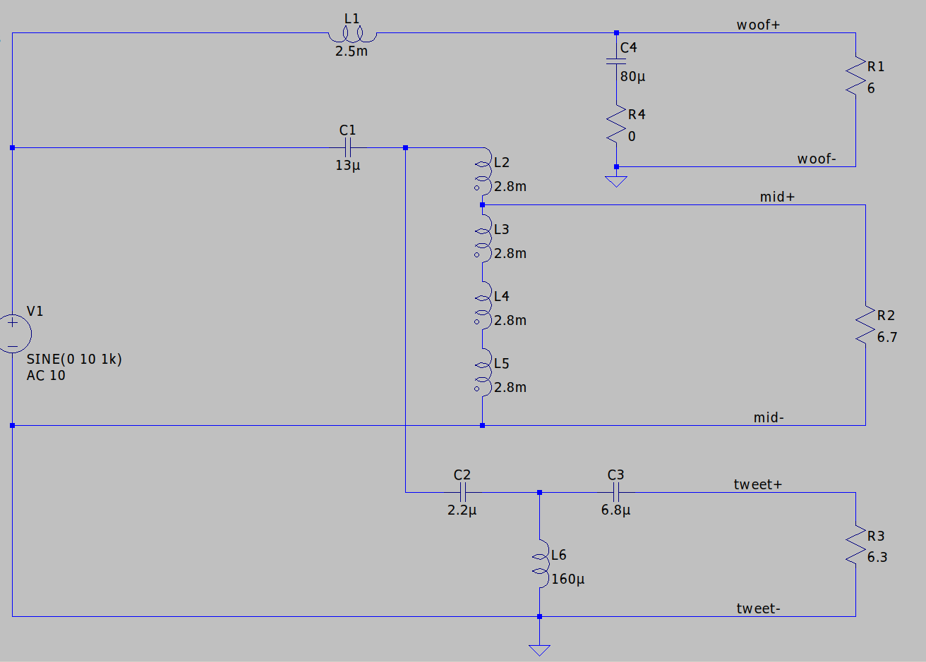
Here is the woofer network, with and without the added voice coil inductance. The RLC equivalent model of the T/S parameters are left out because they won't make a difference for this simulation as we only want to see the difference the voice coil inductance makes electrically in circuit. As expected not a discernible difference.

-
We were discussing 3 way speaker crossover points and since voice coil reactance increases with frequency it was only natural for you to find a scenario where the woofer crossover is more than an octave higher than the discussion where the reactance is higher. Moving goal posts to fit your argument is what I am talking about.
-
It should be a huge red flag that your "model" doesn't match what you are measuring, which tell us that your model is obviously flawed. I looked up the T/S parameters and made a more accurate model and low and behold the simulation shows the same resonance and frequency response you measured.
-
How can you take your simulation seriously when your speaker model is incorrect? You can't measure the variables I asked for, they need to be calculated from the T/S parameters of the speaker. For example your model says the resonant frequency is at 43.8Hz which is wrong, it should be 29Hz.
-
Can we see an impedance plot for your speaker model? It just doesn't look right to me. I looked up the specs for the Philips woofer and the numbers don't match. Can you show how you calculated the moving mass capacitance, inductance of suspension compliance, suspension resistance, and air load capacitance?
-
Also, of course I know that the voice coil reactance will increase with frequency from DC up, but again in the context of the discussion it won't in a meaningful way until you are up into the stop band part of the woofer network.
-
Judgement call? How? These are defined by the crossover points which makes my assumptions of frequencies below it will be in the pass band and above it in the stop band correct. It has to work out this way as it's the nature of the filter network's application. Moving either left or right from the "chosen" crossover frequencies this assumption rings true. Can you provide an example where the voice coil inductance will create an issue with the network? I think it makes complete sense that the reactance of the voice coil will only be an issue when near the crossover frequency because if it's not then it's either in the pass band or in the stop band part of the network. So for the woofer the reactance increase will be in the stop band, there is no getting around this. For the tweeter it will be in the pass band, there is no avoiding this either. In context to the 35Hz resonance we are -7° phase shift, insignificant if you ask me.
-
I was told to look at the bigger picture, which is exactly my point. You cannot ignore the nature of the filter you decide to choose because ultimately it will have an effect on the acoustic response. Example, choosing an even number of filter elements vs odd numbered, they will have different phase characteristics you cannot ignore. It's not always about amplitude and slope steepness.
-
I never once stated acoustic response was not important. I am only saying choosing a specific filter will have it's pro's and cons and as the engineer you need to pick your trade offs. For example the third order filters often chosen because of their steeper slope BUT because of it's phase response it's impossible to correct so it's a trade off. Shouldn't one strive for a flat transfer and then look at the acoustic response? Who wants a resonance smack dab at the crossover frequency? I was specifically asked by Chief Bonehead this question and I stated that I feel both the transfer properties and the acoustic response are important. As stated above, I am not disregarding acoustic response and never said it's not important. I know it's a complete system I just tend to solve one problem before solving the next. Let's put numbers to it then. Eminence Kappa has a voice coil inductance of 1.4mH and the drivers resonant frequency is 35Hz. Ask yourself how will the voice coil reactance effect the network? Well, the resonant frequency of the 1.4mH and 80uF capacitor is 475Hz, as I already stated the problems arise near the crossover frequency. The 35Hz resonant frequency is in the networks pass band where it's flat with a 0° phase shift. How will this effect the network? The 1.4mH voice coil inductance will start to increase in impedance with frequency in the stop band part of the network. Again how will this effect the network? I have added the 1.4mH voice coil inductance to the simulation and it changes nothing as expected which is why I left it out to begin with, crunching numbers quickly led me to this conclusion and the simulation confirms it.
-
I apologize if I didn't explain it well. You seem to be hung up on load so lets deal with that. The application of a Butterworth filter as we use in these crossovers is known as a Cauer Topology and the maths depend upon whether you have even or odd number of filters and load isn't even a variable. I tried to make it clear that when discussing the transfer characteristics they only occur at a specific frequency, in our case the crossover frequency, this is where the filter goes from pass band to stop band. So worrying about the driver impedance vs frequency isn't necessary as I will try and clarify. For the woofer, any anomalies in regard to changing impedance with frequency will be dealt with by the amplifier or not important. For frequencies below the cutoff point we will be in the pass band of the filter (view it as a straight wire because impedance of the series filter networks are low since we are in the flat part of the filter transfer curve. This means the amplifier will see it directly. For frequencies above the cutoff point we are now in the stop band part of the filter where impedance is high for the series element and the shunt element has a low impedance shunting signal to ground so the drivers change in impedance vs frequency is also moot here. The only place of importance is where the corner frequency is. Let's look at the tweeter. For frequencies above the cutoff frequency we will be in the pass band part of the filter network (low series impedance, high shunt impedance) and you can view the filter network as a wire because of the low series impedance, the amplifier will now see the tweeter directly and deal with it's anomalies directly. If we go below the cutoff frequency we are now in the stop band part of the filter (high serial impedance and low shunt resistance), and this means that the amplifier isn't even seeing the tweeter because the shunt element is of low impedance and dumping the frequencies before getting to the driver. So the only places for us to have to dial in is where the cutoff (crossover) frequencies are. Is that a little clearer?
-
As a speaker engineer you can choose whatever filter you feel is best but they are still strictly defined by specific mathematical equations with very specific transfer characteristics. The transfer characteristics or cutoff characteristics is where we enter the stop band part of the filter, not the pass band. In a crossover network these points happen to be where the crossover frequency is. It seems complicated to have to worry about the changing of impedance over the entire frequency range but you don't have to really. Take the woofer circuit, the inductive reactance from the voice coil will increase at high frequencies changing the load impedance but it's moot because we are now in the stop band part of the curves where it's attenuated as it's the woofer we are discussing, you only have to worry about the frequencies coming through the woofer which is in the pass band part of the filter and flat. It just happened to have a resonance via the capacitance chosen just at the knee of the transfer curve, all that was needed was to be damped to keep the filter curve flat, it had nothing to do with the type of filter that was chosen. For the tweeter, the voice coil reactance is so small compared to the woofer that it will only come into play at an even higher frequency which is moot because we are now in the flat pass band part of the tweeter network anyway. The reactive elements of the drivers shouldn't create a problem for the filter network designs. The way I view it is I would want a flat transfer for all crossover points then move onto making the acoustic frequency response flat. As noted it wasn't the actual choice of filter type that gave us that resonance it was the 245mH inductor and 80uF capacitor that happened to put a resonance right at the worst spot, right at the end of the pass band just before the stop band "knee" making a +1.6db boost. All the important stuff is only happening right where it goes from pass band to stop band which is a specific frequency, so all we as engineers have to do is make sure it's a flat transfer and it's all good. The rest of the changing impedance vs frequency from the driver coil is kinda moot because it will fall either in the pass band or stop band part of the filter.
-
Ideally both. The transfer function comes down to each different type of filters cutoff characteristics, and is mathematically defined. First order Butterworth (-6db/octave slope) is phase coherent, the outputs combine perfectly. But it's very demanding on the drivers, they need to be able to handle and faithfully reproduce frequencies slightly outside their sweet spot. A second order Butterworth steepens the slope up to -12db/octave but the outputs are 180° out of phase which is why you see the tweeter leads flipped around. Most Klipsch crossovers are third order Butterworth which has fast rollof of -18db/octave with good phase characteristics. The outputs phase sum together well in either polarity, and the phase response is a gradually changing shift over the audio range. The pitfall of this design is it can not be corrected using time delay for the case where the loudspeakers do not radiate from the same vertical plane. I kinda like the fourth order linkwitz-Riley Crossover. The outputs sum with flat frequency response, the outputs are in phase at the crossover frequency, and the phase relationship of the output allows time correction for drivers that are not in the same acoustic plane.
-
Extremely common with newer subwoofers not using a linear power supply. I went back to using a linear power supply subwoofer for better reliability. At one point I would go around and collect broken subwoofers from people either tossing in garbage or trying to sell for parts, most I ever paid was $20 for them. I would then take them home and fix them and gift them away to friends that had 2 channel systems that were not convinced on going 2.1 with a sub, this way there they could get their toes wet without paying anything. Many still have the units I gave them or liked the results so much they upgraded to better units. I would remove the plate amp and mail it out for repair. I believe there was this college kid on here doing subwoofer repairs but he seemed pretty back logged and seems to be not responding. If he won't help you let me know and I don't mind helping out, I hate seeing things go to waste for something that needs $20 in parts and hour or two of time.
-
Good question. Since we are seeing in the electrical simulation that the ~355Hz resonance from the 245mH inductor and 80uF cap is now damped better, it should be a more accurate transfer of signal to driver. And, if whatever speaker the network is installed in has any anomalies in that frequency range it will exacerbate it less vs the peaking non-damped signal. So in short, I imagine a cleaner image and more accurate reproduction. I will try and find the woofer voice coil inductance or even measure it if I have to and add it in series to the DCR load in the simulation.
-
Carver Crimson 275 - Has anyone heard one?
captainbeefheart replied to pzannucci's topic in Talkin' Tubes
Yup!! Frank has been pushing these amps on Bob's name not caring one bit that he is fudging the specs like mad and totally lying to peoples faces laughing all the way to the bank. I am not a fan of him and like yourself cringe anytime I have to listen to him or read anything he says. He is a business guy, knows nothing except where to cash the checks. -
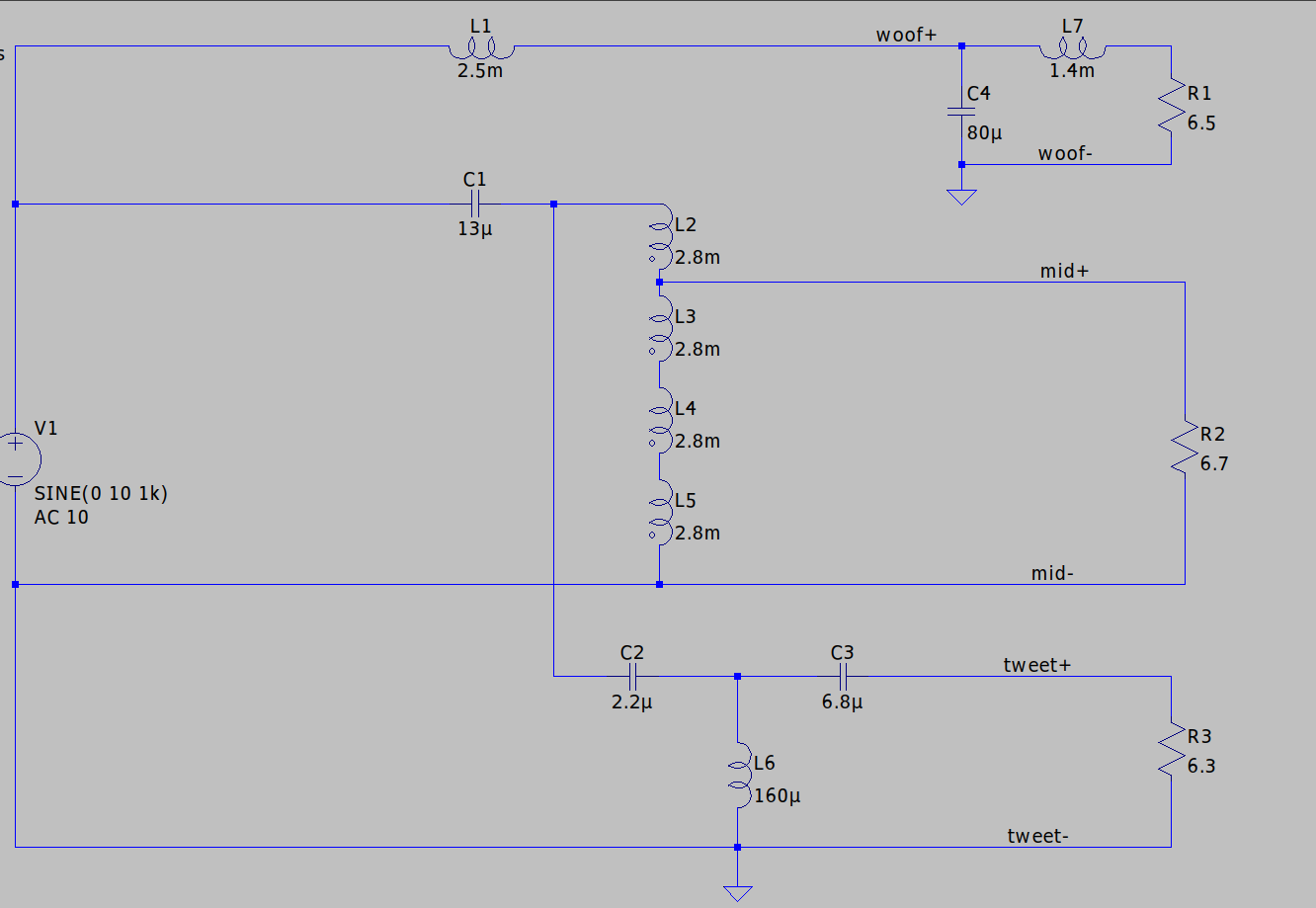
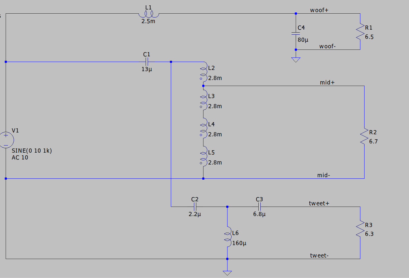
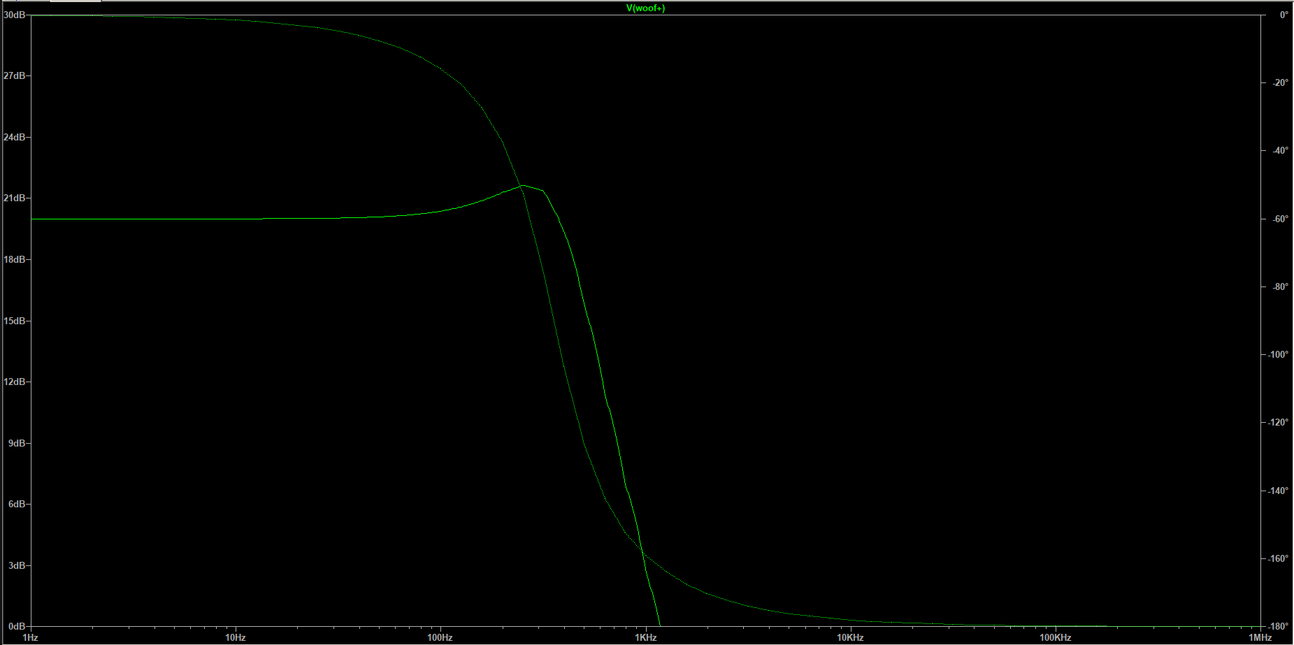
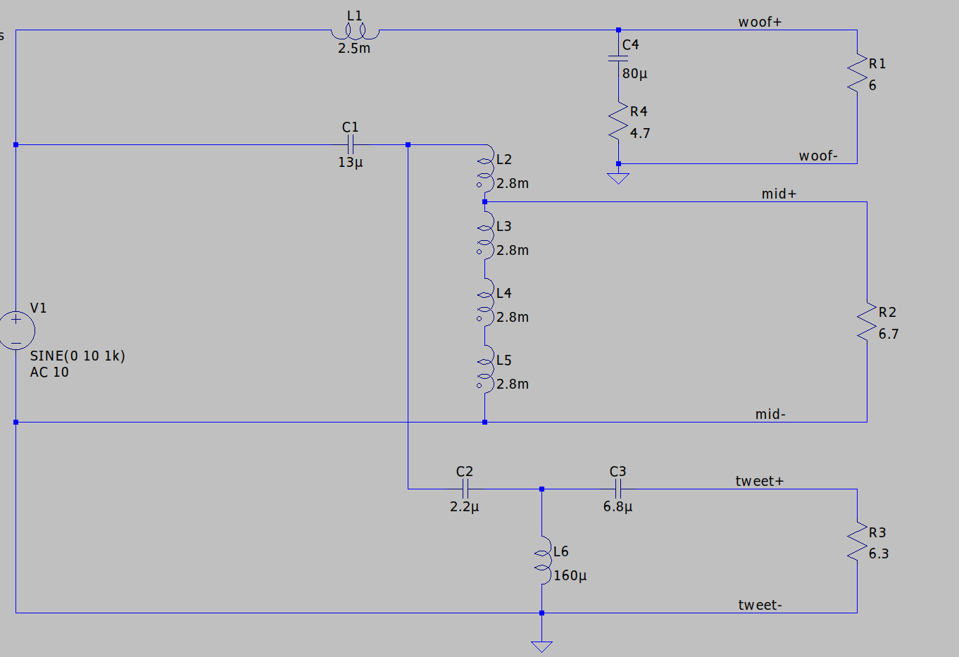
This simulation shows the extra ESR from the aluminum electrolytic dampens the resonance. Instead of adding the ESR into the capacitor model I just added a resistor in series in order for people to see I am actually adding the resistance into the circuit and it clearly showing a MUCH flatter response.
-
Carver Crimson 275 - Has anyone heard one?
captainbeefheart replied to pzannucci's topic in Talkin' Tubes
I wouldn't put this on Bob Carver either, Frank Malitz is the problem. -
Carver Crimson 275 - Has anyone heard one?
captainbeefheart replied to pzannucci's topic in Talkin' Tubes
Jim Clark confirmed the Carver amps use the same tiny Edcor transformers as seen in the two amps tested in that ASR thread. All you have to do is have someone install some real output transformers in those amps and possibly up the bias a bit to get rid of the crossover distortion and those will be killer amps. Still you probably don't need more than the 15 watts if you have been happy with it. Jim Clark is assuming those were carverfest amps, one possibly but the boards and everything look exactly the same, the signed version the guy tested looks identical even where the signature is placed. I doubt someone disassembled parts in the middle of Carverfest to have him sign it in the exact spot production models are signed. Before you take it off to a tech a simple removal of the transformer cover and some pictures of the output transformers will tell us all we need to know. You just can't escape physics, big power with transformer coupled amps need big transformers. I am willing to bet it has the small Edcors like all the others taken apart. -
Carver Crimson 275 - Has anyone heard one?
captainbeefheart replied to pzannucci's topic in Talkin' Tubes
Jim Clark doesn't know anything about the working of electronics and even says so in his post in that thread. As Jim states and also has been measured it does make 60 watts because of the chosen load, B+ and tube gm but only at middle frequencies, say like in the tests at 1kHz. But the transformer needs to be large enough to not saturate and distort the waveform which is why these amps perform so poorly over 15 watts, at 60 watts 1kHz distortion was grossly high in these amps and should not be considered even mid-fi. Distortion just gets worse as you get further out with frequency and power. It just has too small output transformers is the problem. I would stay far away from these amps, these measurements have been confirmed by many people not just in that thread. They even boast the amps only weighs 17 pounds which should be a huge red flag right there with any output transformer coupled tube amp of high power. These amps do run very cool, they have a sliding bias scheme where at high signal levels the bias shifts more negative to keep the tubes running cool. It's also supposed to help blocking distortion, I have never tested the circuit scheme myself. I figure just go Class 2 grid drive operation and be done with it, never worry about grid blocking distortion ever again. I mean if you come across one for peanuts and know you are getting a decent 15 watt tube amplifier then go for it. Just be an educated consumer.