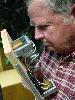
BEC Posted June 19, 2006 Share Posted June 19, 2006 The Heresy II crossover is built on the back of the plastic input terminal cup. I know that Chris Munson has an excellent replacement for these crossovers, but if you are interested in just a rebuild, here is a way that can be accomplished in a bit cleaner than factory way. The early ones like in this picture can be a rather challenging rebuild since things are pretty crowded up on the round cup. Bob Crites Quote Link to comment Share on other sites More sharing options...
BEC Posted June 19, 2006 Author Share Posted June 19, 2006 The later ones have more room and use a circuit board. Bob Crites Quote Link to comment Share on other sites More sharing options...
BEC Posted June 19, 2006 Author Share Posted June 19, 2006 Anyway, for either type, you can remove the autotransformer and inductors and mount them on a board. The caps can then be replaced and a terminal strip can be installed on the new board. Then, you can just run a set of wires from the old input terminal cup to the new board. Mount the new crossover with a couple of screws in the bottom or on the side of the cabinet and run the driver wires from the terminal strip. Bob Crites Quote Link to comment Share on other sites More sharing options...
J.4knee Posted June 19, 2006 Share Posted June 19, 2006 Bob you have an e-mail Quote Link to comment Share on other sites More sharing options...
Daddy Dee Posted June 19, 2006 Share Posted June 19, 2006 Bob, That looks very good. I need to get those HII crossovers to you. Quote Link to comment Share on other sites More sharing options...
soundbound Posted June 20, 2006 Share Posted June 20, 2006 Nicely done! Quote Link to comment Share on other sites More sharing options...
oldbuckster Posted June 20, 2006 Share Posted June 20, 2006 Whata Guy, very nice, old world craftsman............ Quote Link to comment Share on other sites More sharing options...
awsjr Posted June 20, 2006 Share Posted June 20, 2006 that square circuit board is the type I have/had.....I used Solen 68uF and 3 auricap 1.5 bypassed with a RelCap TFT 0.1 (don't asked), Solen 2.4 12awg and litz .15 14awg inductors....rewired with Kimber TCX 15ga wire.....not the neatest looking job but it was a first attempt.....sounds very good.... Al Quote Link to comment Share on other sites More sharing options...
Deang Posted June 20, 2006 Share Posted June 20, 2006 I wonder how many HII's have that circular cup with the mess on the back? I guess I'm thinking that the new board approach is almost mandatory for those, but for the later models with the nice PCB -- and if you're just going to do the caps -- it's not necessary. I also think if someone is going to go through the trouble -- Al has the right idea. Quote Link to comment Share on other sites More sharing options...
Guest " " Posted June 20, 2006 Share Posted June 20, 2006 that square circuit board is the type I have/had.....I used Solen 68uF and 3 auricap 1.5 bypassed with a RelCap TFT 0.1 (don't asked), Solen 2.4 12awg and litz .15 14awg inductors....rewired with Kimber TCX 15ga wire.....not the neatest looking job but it was a first attempt.....sounds very good.... Al i had a set of these from 1992 thru 1999. I replaced my xovers and mounted them up-side down under the top of the cabinet. I did'nt mount them on the bottom becaused I was worried about the magnetic feild strenth of the woofer. Not really sure if the concern was vailid. Quote Link to comment Share on other sites More sharing options...
Deang Posted June 20, 2006 Share Posted June 20, 2006 I was worried about the magnetic field strength of the woofer. Bob calls air cores "look'in for a core". That's definitely a downside with using them. I was so enamored with the work in the pic I hadn't really thought about that woofer magnet hanging over the board. I would be inclined to move it somewhere else! Quote Link to comment Share on other sites More sharing options...
popbumper Posted June 20, 2006 Share Posted June 20, 2006 I just did a Heresy II crossover rebuild using my circuit boards, but instead of the stack configuration, mounted the boards on standoffs side by side to a piece of MDO plywood. It turned out very nice, the customer was happy with the results, and not being a stack, it took up less room and fit better in the cabinet bottom. If anyone is interested in this option, I would be happy to help. The K-stack boards are very versatile. Chris Quote Link to comment Share on other sites More sharing options...
awsjr Posted June 20, 2006 Share Posted June 20, 2006 tell me about the interaction between the woofer magnet and the inductor ......is it harming the magnet or is it affecting the cross-over ?......any idea what the distance be from the magnet to the inductors to insure no interaction ?......thanks-Al Quote Link to comment Share on other sites More sharing options...
Guest " " Posted June 20, 2006 Share Posted June 20, 2006 tell me about the interaction between the woofer magnet and the inductor ......is it harming the magnet or is it affecting the cross-over ?......any idea what the distance be from the magnet to the inductors to insure no interaction ?......thanks-Al I don't have any scientific evidence to support one position or the other. I have noticed that most high end corssover providers go thru great pains to orient inductors in postions so they are 90 degrees out of phase of adjacent inductors, and illustrate their crossover offerings installed away from magnets, even if they have to split the crossover board and put half on one side and half on the other side of a nearby driver. I don't think the issues is damage to the magnet. Quote Link to comment Share on other sites More sharing options...
awsjr Posted June 20, 2006 Share Posted June 20, 2006 thanks.....yes the crossover inductor positions are somewhat critical, like with the extreme slope designs AL K offers.....although my heresy's sound great as is, this is going to drive me crazy.....I am going to pull the bindings post hatch and take a look at how close the woofer magnet is to the big inductor....maybe with a screw driver or something I can get an idea of the range of the magnetic field..... Quote Link to comment Share on other sites More sharing options...
Malcolm Posted June 20, 2006 Share Posted June 20, 2006 Geez, BoB. All that work and you didn't replace that tacky electrolytic...[] Quote Link to comment Share on other sites More sharing options...
BEC Posted June 20, 2006 Author Share Posted June 20, 2006 Geez, BoB. All that work and you didn't replace that tacky electrolytic...[] I will have you know that is a brand new tacky electrolytic. And, no need for anything better in that place. Bob 1 Quote Link to comment Share on other sites More sharing options...
chops Posted June 20, 2006 Share Posted June 20, 2006 Yeah, that's the same tacky electrolytic that I'm using in all three of my front speakers also! [] Quote Link to comment Share on other sites More sharing options...
Deang Posted June 20, 2006 Share Posted June 20, 2006 For where it's at -- it's good enough. Quote Link to comment Share on other sites More sharing options...
Guest " " Posted June 20, 2006 Share Posted June 20, 2006 I'll pass it....since there is no stripe on it. Quote Link to comment Share on other sites More sharing options...

Recommended Posts
Join the conversation
You can post now and register later. If you have an account, sign in now to post with your account.
Note: Your post will require moderator approval before it will be visible.