mikebse2a3
-
Posts
4828 -
Joined
-
Days Won
1
Content Type
Forums
Events
Gallery
Everything posted by mikebse2a3
-
Auto-transformer T2A or #3619/3636?
mikebse2a3 replied to DizRotus's topic in Technical/Restorations
Got It! Thanks Trey For The Information. mike[] -
Sounds like a good idea, but it's a little tight under there. Under multi-stage cans at www.tubesandmore.com they have JJ Telsa surface mount cans at 100uf/100uf at 500vdc versus what's in there now on C9 and C10 which are single stage 100uf/at 450vdc. Could I use these cans and simply wire one 100uf stage? and would the 500 vdc rating affect anything? This would give me sufficient room underneath to wire in the 100/10 power cap on C9. thebes I'm not sure I understand clearly what your asking here. The main thing I want to tell you is C9 must be insulated if its used as above the chassis as the orignal otherwise you would have a 325volt shock hazard!!! C9 must be totally isolated from ground!!! and if you used a 2 section one in its place both sections negatives would be common so only one section (EDIT: actually both section can be wired in parallel as Rick Suggested below but no section of the C9 can be used in place of any section of C10 or C11) could be used to preserve its isolation from ground and its outside case MUST BE INSULATED!!! Did you mean that you would only use one section of the new capacitors? If thats the case that would be fine. If wire lengths will permit you could use one of these new 2 section 100/100 filters in place of C10 and C11A(since both these have their negatives tied to their cases and to ground) and then wire in a single 10mfd 400v cap in place of C11B. The 500vdc will work in place of the 450vdc filters. thebes you can go up but not down in voltage ratings. -------------------------------------------------------------------- I'm sure it's hard to tell from the pictures but on both amps C9( is wired in the same way, so I wondering if it's still in the circuit since one wire (the 10mfd side) goes to the 7247 tube and the 100mfd side goes to the standby controler (which uses a shorting plug on top of the amp to bypass the controller). thebes the way I read the diagram That is the filter marked (C11A and C11B which is located next to the Audio Output Transformer) and not (C9 which is physically located in the middle of the three filters) Which leads me another question are all these various caps omnidirectional or do they have plus and minus side to pay attention to so they are not wired up the wrong way? May sound silly but I really don't know. thebes good question and yes the electrolytics power supply capacitors are directional and most common to be found is the negative side is the case of the Can of the filter with the positive as the insulated lugs comining out the bottoms of the filter. ----------------------------------------- That's been driving me crazy to. Because six of the eight resistors in both amps are the 15ohm/2 watt and 2 are 15ohm 1 wattt so I'm wondering if the factory simply made an error on the schematic or this was some sort of common mod for these things, since the soldering on most of these looks to be original. The modded one, by the way, runs fine. A little hum and static on startup and dead quiet after a minute or so. I've run in for 2 or 3 hours so far with no problems, excesssive heating or anything else, so I'm thinking the 15 ohm's should stay. And yes all of them do go to Pin 3. Regarding biasing your advice and recommenations are taken to heart. I think I may be stretching my skill levels too far re bias mods, so I think I'll just set the pot about half-way, make sure the tube plates aren't glowing, and take it to a local tech for biasing once the tube have burnt in a bit. I'll also get matched tubes. The modded one is using EH's so I'll stick with that. I can always roll something else in down the road. thebes (aka Marty) I agree the 15 ohms/ 2 watt could have been a factory change at some point and should be fine. As far as the biasing what you have is a balancing control which will allow you to get the least noise(HUM) and balance the current some between the push/pull section (V2/V3 and V4/V5) of the output stage. With no music signal playing you can measure the voltage drop between the center tap(negative lead of the meter set on DC of the balance control and alternating the Meter's (+) lead between bot side lugs of the control till they measure as close to the same voltage as possible. You should also hear the least hum through the speakers when the balance control is adjusted at its best position. thebes your welcome to e-mail me(put thebes in subject line so I want accidently delete it) and I can give you a phone number or give me yours and I can use my cell for free long distance after certain hours if that might help you to work on this project mike: aka one of the good mikes[]
-
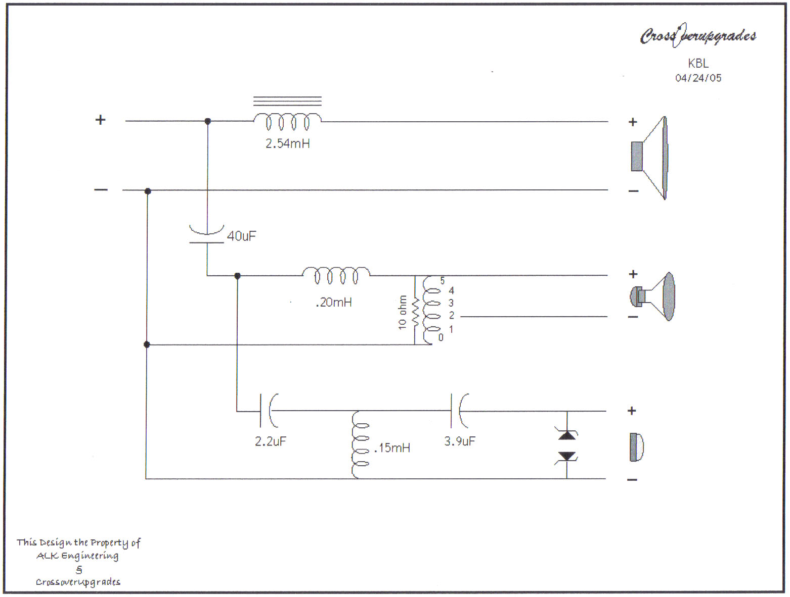
Thanks all for your explanations. Erik Yes anytime two capacitors are wired in series the equilivant value is less than the smallest value. I knew just by a simple theoretical calculation of the impedance of the 40mfd that for all intents you could consider the 2.2mfd as tied to the input's (+) and thus my question of what other benefits was there to this hookup. So considering that the theoretical is affected by real world conditions(ie like capacitors that don't measure as theory would calculate at higher frequencies for one example) a large value capacitor might exhibit some problems at the higher frequencies and that there might be an audible benefit to actually hook the 2.2mfd directly to the input.(even if the value needed to be tweeked slightly say to 2mfd in your example. djk Yes that is what I was thinking that somehow there might be some phase advantage for this hookup but considering the phyiscal difference in locations of the tweeter and squawker that any benefits of this was lost in the case of our klipsch speakers. Dean LOL! I like youe style!!! I would have to have done as you and tried the other connection for any audible differences I might have perceived. AL K Thanks for taking the time to explain this. So if I understand you correctly this hookup in theory will give you the smoothest impedance curve of the crossover network as its main benefit in our klipsch speakers? AL K said: The 40 uf and 2.4 mHy forms the woofer / squawker cross and the rest of the network is the squawker / tweeter cross. This is true for the "Super AA" and all my network designs. To move the high crossver input to the common input completely louses up the low crossover! How would moving the tweeter hookup position screw up the low crossover? By low crossover are you refering to the woofer's crossover or possibly the Squawkers? So my orginal question and thought was if the 2.2mfd connection was moved to the (+) input terminal then it seemed to me that the impedance would only be effected slightly(If this assumption is correct) with the benefit of not passing all the tweeters signal through the 40mfd and this could have had an audible benefit that some might want to try. (note: Dean did try this and thought the original sounded best.) Again AL K thanks for explaining your network design. mike[]
-
I have a question for AL K or Dean that I've wondered about for awhile. I've noticed the tweeter portion(input to 2.2mfd) of the network is being taken off of the 40mfd instead of being connected directly to the (+) input from the amplifier and was wondering what advantages are you receiving by this method? Otherwise it seems to me that it would be better not to pass the high frequencies through the 40mfd for less chance of high frequency signals being degraded. mike[]

-
Auto-transformer T2A or #3619/3636?
mikebse2a3 replied to DizRotus's topic in Technical/Restorations
I'm not seeing any picture in Trey's post (it is just showing a red X in the box) can any of you see anything? -
My bad. Yes all the caps I was talking about are .47, .22, 600vdc the same with the 3 white ones you can see in the left of the picture on the modded bogen. Your cautionary advice on the dangers of fooling around with electricity are taken to heart and I will discharge thecaps before working on them. Oh, can the power and filter caps be discharged through grounding or will this hurt them? Yes and you might want to use a resistor to do this! A 1K 10watt or something in this range is often used for this purpose to limit the discharge current from the filter. Since C9 is isolated from ground it might be best to discharge directly across it to make sure it is totally discharged. The mods by the way are very simple. Wires are simply connected between pins one and eight on V1,2,3,4 (the tubes sockets) and the 10k resistor at R26 is upped to 22k. Also some wires have been relocated off the tubes to a terminal strip installed just below the bias pot. Yes on a EL34 the supressor grid(1) is kept at the same voltage potential as the cathode(pin8). If I'm seeing the schematic numbers correctly R26 is the resistor to ground after the (-) voltage bias circuit's diode and upping its resistance should increase the amount of (-) voltage biasing the EL34s. whether it is enough I wouldn't say until I took a reading of the standing current of the EL34 tubes. I'm also including a picture of the top of the modded amp which shows the C9 filter cap with the loose cardboard removed and some crumbly tar type stuff on top of the can. Values off the cans for c9 and c10 are written as 100mfd 450 vdc, operating temp 85c. Values for the c11 caps as read off the caps themselves are given as: 100mfd at 400vdc and 10mfd at 400vdc, operating temp 85c. Just so you know when Filters are used in a voltage doubler circuit like this if one goes bad it can cause the other to overheat and I've even seen them explode in a few cases. I'm not sure thebes but I would probably just keep the orginals for looks and see if I couldn't work new Filters with some wire terminal strips under the chassis to save money and also for safety reasons since I'm not sure how easy it would be for you to find Filters with the insulation of the case like C9 would require to maintain safe operation. I'm not so sure that filter cap c9 has been bypased because there are still wires going into and out of it. The only difference between the wiring on both of them is two small resistors (?) to the left of the resistor with the orange bands on it. They read N1 on the original and are smaller then the 2 in the modded one whose values I cannot read without desoldering them. Yes in this case C9 is just bypassed since it is probably opened but it could be causing some high resistance in the circuit and still would have the potential to short some day so I would want it unwired if it was me. Not sure but I believe you are talking about the Silicon Rectifiers. One set looks silver and the other look like black plastic(which will probably have a line on one end for identifying the cathode) So based on this any changes in recommendations? Also can I get new filter caps and power caps for these of the same type so I can keep it looking original? When Craig redid my Scott 299 he replaced the cardboard covered filter caps with nice shiny plastic black ones so I'm hopeful but need your advice. Again if it was me, since these values are easy to come buy and they are avaible in physically smaller size now I believe I would just buy the capacitors and install under the chassis and I believe this would save you alot of money also and be safer! Also any recommendations on brand names etc. I don't think I need to put in the top dollar stuff but I do want this to sound sweet. I would just make sure they are rated for at least 85c and you might even find some rated at 105c for about the same cost. Also is there a simple mod so that I can bias this thing using a multimeter? This brings up the plate resistors which on the original schematic appear to be valued at (39ohm 2w) but if I'm seeing the wiring correctly they have been changed to (15ohm 2w). These are wired to Pin 3 of the EL34s aren't they thebes? You would have to be very carefull since we are dealing with very high voltage here but If these are the plate resistors then current could be read from them by callculating the voltage drop across them. I = E/R which would be in your case Current = Voltage Drop/15ohm You might be able to modify the amp some and install some 10ohm 2w resistors in series with the cathode of each EL34 tube and this would be much safer since the voltage potential here is very low. The way the Amp is built now V4/V5 and V2/V3 EL34s should be matched and it would be even better if all (4) EL34s where matched to get the best performance and lowest noise from the Amp. I suppose if you are willing to modify the bias circuit some and purchase more controls you could get to where you could bias each tube seperately. Its hard to give advice like this when you don't have the amp in front of you to see what obstacles of mounting and wireing things in might be but I hope this helps some thebes. mike[]
-
thebes I'm not sure but after looking at the schematic it looks like the (2) caps paralleled you were asking about might be .22mfd instead of 22mfd = .44mfd instead of 44mfd so you might want to double check those and the one you said was 47mfd could be .47mfd . These caps look to be the caps that are feeding the (-) bias voltage circuit according to the schematic. Its hard to tell by your pictures but as I've looked at the schematic and back at your pictures it looks like the (3) section Electrolytic Capacitor that I thought you had is actually the part marked C11 and is instead a (2) section Electrolytic Capacitor. The two Electrolytic Capacitors marked C9 and C10 on the diagram are part of what is called a voltage doubler circuit and if you notice C9 is isolated from the chassis and thus ground. I believe C9 (the middle capacitor of the 3 can capacitors) will have an insulated case (probably cardboard/paper wrapped) so be carefull around it if any insulation is off of it the case will be at about 325 volts potential!!! Is one end of the 15 ohm resistors you asked about hooked to pin 8 of the EL34(formerly 8417) tube socket? Also is the Output tube Balance control still wired in the circuit? Since this amp has been modified it hard to be sure what to tell you about it since we can't see it for ourselves. More pictures of under the chassis would probably help us to try to figure what has actually been changed about the amps. mike[]
-
thebes I can't tell for sure from your picture but the (2) 22 mfd caps you have in the picture kind of looks in the picture to me like someone was just replacing a bad section in the (3) section Electrolytic Can Type Filter (these are usually silver looking canisters). If those (2) caps are soldered to that Electrolytic Cap section then I believe you should replace the whole Electrolytic Filter. If you look closely at the bottom of that Electrolytic Filter it looks in your picture like it is begining to leak(The Black Rubber looking stuff) out the bottom. mike[] Edit: Thebes any Electrolytic Filters that show signs of a black or tanish brown like material leaking out around the terminals or openings in the bottom should be considered bad.
-
Bruce And Josh Through Life's Trials And The Loss Of Many Loved Ones I've Come To Believe This To Be True Life Isn't About How Long We Live But Instead It Is About How We Live And How We Love And Share Life With The People In Our Lives. Sounds Like Barbara Lived Life Wonderfully! GOD BLESS mike
-
"Headroom" - what does it sound like to you?
mikebse2a3 replied to ben.'s topic in 2-Channel Home Audio
OK DrWho! I'm going to try to get some sleep so will you keep it down some?[] mike[] -
"Headroom" - what does it sound like to you?
mikebse2a3 replied to ben.'s topic in 2-Channel Home Audio
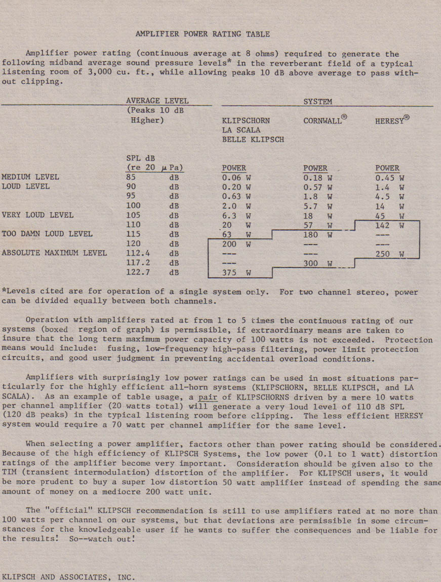
WHY? I still say my required 120db peak is met without any change since unlike you I am saying the extra dynamic range is being used to lower the quiter passages and thus the average will lower. All the extra dynamic range we have with CDs for example wasn't necessarily to raise the ultimate peaks but instead was used to give a greater range between quite and loud passages (that was maybe compressed before)and to lower the noise floor of the recordings. mike -
"Headroom" - what does it sound like to you?
mikebse2a3 replied to ben.'s topic in 2-Channel Home Audio
Actually the way I look at it lets take the Khorn with (20 Watts will allow peaks up to 120db in the DFH Paper). So if we have recordings with say an even wider dynamic range why would we necessarily want to raise the peak levels? Why wouldn't the extra Dynamic Range actually be used to widen the loudest to quitest passages and lower the noise floor of the recording. Yes this would mean the average level we would be using would be lowered but with the peaks still at 120db. Even Wider Dynamic Range Recordings doesn't mean we necessarily want or should raise the ultimate peaks of the recording. mike[] -
"Headroom" - what does it sound like to you?
mikebse2a3 replied to ben.'s topic in 2-Channel Home Audio
2nd page
-
"Headroom" - what does it sound like to you?
mikebse2a3 replied to ben.'s topic in 2-Channel Home Audio
Good Advise in 1977 and 2005
-
Your a Good Person and I Pray The Best For You. Mike[]
-
How do you know if your K-77 tweeters are working?
mikebse2a3 replied to Corvette6769's topic in 2-Channel Home Audio
In your case it's probably just a difference in model types. But one thing that can happen on the K77 and K77M to cause the SPL Level to shift is a bad connection where the rivit and solder terminal contact each other on most models. Be carefull and don't wiggle the terminal much but if you can touch it and the SPL changes then you can fix this pretty easy if you can solder. The voice coil wire is often just run through the rivit and soldered and the wire soldered hookup terminal just makes contact with the voice coil/rivit by the pressed rivit joint. Over years the pressed joint can become oxidized and not make good connection. I have fixed many of these by taking a very fine copper wire and wrapping it around the wire terminal and soldering this end and then leaving a little slack solder the other end to the rivit. By leaving a little slack if the terminal moves you want take a chance on breaking the voice coil wire as easily. mike[] -
Mike, yes the blue spades. Just to be clear for each set (+ and -) you have them going to the same place at the other end? No biamping, bywiring or any other sort of thing going on like they split off and go to seperate locations at the other end of them? Yes,( No Bi-Wire or Bi-Amping), they are just in parallel to equal a larger effective gauge size. mike
-
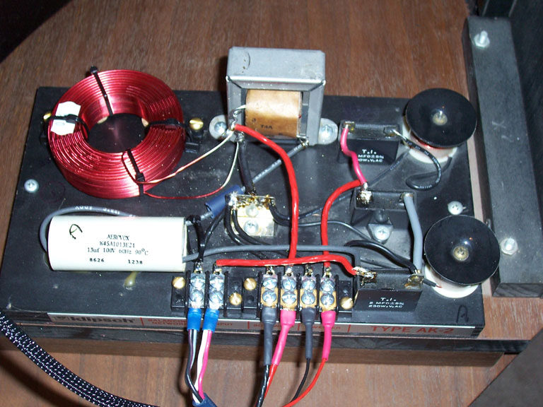
Mike, that would be great. As you know a picture is worth a 1000 words. I did not think it would be that difficult. Perhaps I will do it in two steps. First get it wired up and working wit the just the barrier strip (Not sure where I came up with terminal strip name) modification. Then when I am happy with that I will replace the caps to bring it back up to snuff. Thanks! EDIT, man that was fast...you posted while I was typing - Thanks. One question. In your picture it looks like you have two sets of wires going to each spade on your input connections, why is that? rplace that was some old audioquest wire(if your talking about the blue looking spades) that I was temporarily using and it used 2 wires for (+) and 2 for (-) legs. Also rplace I'm not really sure the capacitors have the same ageing problems as the older oil caps of the A and AA networks but you might want to try some higher quality caps like Dean uses. mike[]
-
here is the AK-2 schematic AK-2.pdf
-
here is the AK-2 changed to an AK-3 with barrier strips installed
-
rplace wrote: Can any of you out there take a look at the pix of my AK-2s and tell me what the various parts are (i.e. little black boxes, white tube, rectangular metal things with windings of wire and black round things with windings of wire), what I should replace to bring them back to factory fresh condition and how to properly wire them with a terminal strip so the right signal goes to the tweeter, squawker and LF sections?<?XML:NAMESPACE PREFIX = O /> ---------------------------------------------------------------- Hi rplace looking at your 1st picture (the 3 little black boxes) these are in the tweeter circuit and they are all 2mfd 250vac capacitors. the (2 black round coils) are also part of the tweeter network. the (white tube) it is a 13mfd capacitor and is in the squawker circuit and feeds signal to the autotransformer. the (rectangular metal thing) the one on the left is a 4mh coil and is in parallel with the squawker the (rectangular metal thing) located in the middle is the autotransformer and should be a T5A. This sets the level of the Squawker I'll try to post a picture af my AK-2 converted to an AK-3 with barrier strips like you want to install. mike[]
-
Yes meagain I'm saying because your wall the Khorns are on is about 12' that maybe leaving the top(horizontal part unsealed could help you in your room and it will cost nothing to try. I've got to leave out but later when I get a chance if you will e-mail me I might have another idea ot two for you to try meagain based on some of what you just wrote. mike[]
-
1. Are you even using all the 60 watts? The Khorns are so efficient you might be surprised. So whether 30 or 40 watts would satisfy you is a good question. 2. I agree with you. 3.Very Wise Thinking meagain on spending money and upgradeing! As far as the loudness level of a 40 watt amp versus a 60 watt amp it would be less than most people think. To actually double the perceived volume level of a 40 watt amp you are looking at a factor of 10 which means close to a 400 watt amp. meagain I tried to e-mail you but it wouldn't go through( something about spaceing) Anyway if you have any questions that I can help with about the EQ/Room/Behringer feel free to E-mail me and just indicate Klipsch Forum in subject line. mike
-
Moral Dilemna: Purchasing and Returning
mikebse2a3 replied to ancientdude's topic in General Klipsch Info
ancientdude I have 2 thoughts to this: If you have to ask you probably know the answer. Treat others as you would want to be treated. This is true whether its an individual or a business which is really made up of many people. mike[] -
Jeff good analogy I agree the EQ can't replace what is caped off in your example. Another point that I think could play a part though is if a room is coloring the sound by boosting certain frequencies and cancelling others one result can be a sense of a loss of dynamics also because again the high peaks to lowest peaks balance is being altered and masked. Lets face it the room is a hugh Equalizer that works in the frequency and time domain and its affect on clarity, detail, dynamics and imaging is larger than any reasonably good quality amp. When you clean the room sound up you will always sense an increase in clarity and dynamics. The sense of dynamics is a function of the loudest to quitest notes in a certain time period. My question for anyone is what maximum SPLs are you trying to reach (with Khorns in this case)? The ultimate SPL you hear at the listening position is going to be effected by room volume, the amplifier's power limits, the speakers ability to absorbe and actually turn that power level into acoustical power. Just because an amplifier could say input 400 watts into a Khorn doesn't mean it will actually be of any benefit because at some point power compression from the speaker system will set in and any power increase will only be absorbed and turned into heating the voicecoil. I would like to share some personel experience about different amplifiers used in one system/room setup. The room itself has a cathedrial ceiling and is easily 35' by 25' and also opening into a large kitchen and large dining room as well so as one can see this is a pretty large space for a domestic listening enviroment. Amplifiers used in this system have been the following: Phase Linear (Solid State, sorry I don't remember the model but very high power) VTL 100 watt Tube Amps (Not sure of the model no.) Marantz 8B (Tube maybe 30 to 40 watts?) McIntosh MC30s (Tube 30 watt mono bloc) McIntosh MC2000 (Tube 130 watt mono bloc) AES SE1 2A3 (Tube approx. 5 Watts) H.H. Scott 222c (Tube approx. 20 Watts) Just to give a couple of examples of some music we have listened to which have good dynamics; Buddy Guy "Blues Singer" Junior Wells "Come On In This House" How did the amps rank/perform? First I would like to say the MC30s are more affected by Tube Rolling than any other amp I've ever heard and can go from sounding as good as any of the above to having some audible issues in this particular room/setup just by using different tubes. All these Amps where able to reach some very realistic sound levels and excellent dynamic sound. The VTL's and the Phase Linear for whatever reasons never really sounded good in this system. There where some noise issues with the VTLs(input sensitivity) and both just didn't have the realism of the rest of the amps mentioned. In a different system this could easily change I suppose. AES SE1 2A3: Of course if you just love cranking the volume to extreme levels then the 2A3 amp isn't for you but what should have been the worst at dynamics (especially for this size space) was audibly the equal of the much higher power amps(yes even on drums and vocals) which simply confirms to me that the Khorns can sound very dynamic with very little power. The 2A3 excels at clarity ,detail and naturalness(especially vocals). The Marantz 8B: Very natural sounding amp and one I could happily live with. The sound stage isn't as wide as some of the other amps but everything sounds very balanced and vocals are very good. The McIntosh MC30s: With the best combination of tubes I feel like it was slightly better than the Marantz 8B but with the wrong tube compliment I would have chosen the Marantz 8B. Tube changes had the most effect in the bass and vocal ranges and when things are at there best this amp is up there with the best. H.H. Scott 222c: This integrated amp sounded as good to me as the McIntosh MC30s and is a great match for Khorns. McIntosh MC2000: This has to be One of the most beautiful amps ever made! The sound was very detailed and vocals where excellent and equaled the 2A3 amp in this regard. Of course with this much power ultimate SPL could easily get you in trouble with the neighbors(this could also be said of the SPL's from the Scott, Marantz 8B and MC30s as well) but it definitly holds together and just gets louder as the power goes up. To sum up my points with all this is that Dynamics was excellent with all these amps and ultimate power available wasn't as important as other qualities of these amps for musical reproduction. Price also wasn't a good gauge of ultimate musical enjoyment either because the H.H.Scott 222c worth approx a few hundred wasn't blown away by the almost $16000 new retail for the MC2000. The sound was so close between the MC2000, MC30s, AES SE1 2A3, and H.H. Scott that I personelly would be happy with any of them. I believe a good amp is important and we will have preferences for the small(relative to room differences) differences between them in our systems but room conditions can easily color and mask alot of the differences in our electronics. meagain I like to always hear peoples opinions and personnely I try to have an open mind and their is no subsitute for trying things yourself in many situations to get a grasp of what will work for your situation and personnel preferences. Try to enjoy this hobby and my best advise is when you are trying different things try at some point to relax and enjoy the music without analyzing what your system is doing right or wrong. The true test is when you forget about the equipment and just become touched by the music then you've got something! mike[] Edit: Better write a quick disclaimer here. Man it takes me a while to write a post sometimes and just to make it clear when I started this post. So during this post I wasn't aware of the other post from others. I really don't want to get into a 5 Watt versus 500 Watt debate. I obviousely can like both low power and higher power amps and I do like to let people who have never experienced a good 2A3 amp with Khorns hear that combination because it is a very good example that power output is only one aspect to be considered when choosing an amplifier for our music.