Arkytype
-
Posts
448 -
Joined
-
Last visited
Content Type
Forums
Events
Gallery
Everything posted by Arkytype
-
Here are a couple of images of the plane wave tubes at Hope & Indy.

-
Back in the mid to late '70s when I peddled Klipsch, McIntosh, Crown, et al, it was common for the Crown amps (D-150 in particular) to make odd noises when connected to Klipsch loudspeakers. The D-150/Klipschorn combination caused a sound closely resembling someone breaking wind about five seconds after the amp was powered down. When connected to less efficient loudspeakers, the Crown amps seemed to behave themselves post power. Lee
-
Klipsch Forum Member Veterans And Active Duty
Arkytype replied to BLSamuel's topic in General Klipsch Info
USAF 1968-1972. Spent one of those years stationed on Easter Island doing "ionospheric study"-- nod nod wink wink. Lee -
Neil's photo reminded me of Don Peterson who was a Klipsch rep in the early '70s. He drove a VW minibus around the country with a pair of LaScalas inside. Needless to say the sensory experience sitting inside was teeth-rattling! Lee
-
Dave's quest to come up with a low-cost procedure for balancing loudspeaker drivers is laudable. With the availability of low or no-cost acoustic software such as Room EQ Wizard, ARTA, True Audio (Level Two) and microphones such as the Dayton EMM-6, one can easily perform measurements that only a few years ago required spending tens of thousands of dollars in test gear for essentially the same results. In 1967, JPL scientist Dick Heyser revolutionized the acoustic measurement field with his Time Delay Spectrometry technique. The first implementation of TDS required tens of thousands of dollars in test equipment and constant tweaking to assure repeatable results. Now you can download a TDS-based system with a mouse click! Testing your loudspeakers in the listening environment has potential pitfalls such as axial and tangential reflections from walls, floor and ceiling. DrWho wrote: The only way to properly dial in a system is to use a time domain measurement - there are three ways that I know of that work exceedingly well, but I stick to the log-sweep because it's artifacts are well understood and you can do it for free with REW. Agreed. Measurement software with "gating" will allow you to approach anechoic measurement conditions by ignoring all but the direct sound from the loudspeaker to the microphone. DrWho also wrote: ....the SPL meter is an average power measurement device. As such, the bandwidth of the signal being measured affects the overall energy captured by the SPL meter. Hmmm....the last time I checked my Ivie, Bruel & Kjaer and General Radio sound level meters, they all indicated they measured sound pressure level, not average power. Sound pressure level is a measurement of the effective sound pressure relative to a reference value. By knowing the sound pressure level, the distance from the source and the Q, one can compute the acoustic power. You cannot read it directly! DrWho also wrote: For example, if you measured a tweeter that could play from 1kHz to 21kHz, then that's a total bandwidth of 20kHz. If instead you measured a tweeter that could play from 1kHz to 11kHz, then that's a total bandwidth of 10kHz. That will result in a 6dB difference. Electronic circuit noise voltage increases or decreases by 3.01 dBv for each doubling or halving of the bandwidth. Should that "law" apply to acoustic measurements as well? I set up a test using some Krohn-Hite, Bruel & Kjaer, General Radio & Audio Precision gear to test DrWho's contention that halving the acoustic bandwidth would result in a 6 dB lower SPL level. A Krohn-Hite 3384 was programmed with two cascaded 48 dB/octave filters set as HP and two set as LP resulting in a passband from 1 kHz to 21 kHz with 96 dB/octave slopes at each end. Pink noise from a General Radio 1382 was fed to the input of the 3384 and the output was fed to a B & K 2610 and AP SYS-2722. This setup eliminates the measuring microphone, loudspeaker and room--so the resulting measurements should simulate a perfectly flat microphone and loudspeaker in a free field environment. After taking an initial reference reading on the analog meter of the 2610 (set to slow response) and the AP (with a bargraph display of incoming voltage), the 3384 was set to a 1 kHz to 10kHz bandwidth. Rather than seeing a 6 dB drop in level, there was only about a 1.2 dB change. Next, the bandwidth was changed to 1 kHz (1 kHz to 2 kHz) and the result was about a -6.5 dB on both instruments. I tried this experiment at lower frequencies with essentially the same result--halving the bandwidth showed only about a 1.2 dB drop in level. Next week, I hope to do some actual acoustic measurements to see if there is something I am missing. Thoughts anyone? Lee
-
Otari MX-5050 B-2HD or Tandberg TD-20A
Arkytype replied to Mike Lindsey's topic in 2-Channel Home Audio
Mike, Back in the '80s when I was a real radio injuneer, we had a boatload of MX-5050BII 1/2 track decks for on air and production. They were reliable and easy to maintain. For my personal use, I purchased a Tandberg 10XD which is a 3-speed deck with Dolby B and Tandberg's crossfield head technology. My unit was a special order with 1/2 track heads. Using Ampex 456 tape @ 15 i.p.s. and Dolby, the live recordings I made were wonderful with absolutely silent background. BTW, the meters on the 10XD as well as the TD-20A are equalized peak reading so as long as you keep the needles out of the red, you will always make a good recording. The first link below is an eBay listing for a 10XD with a "make an offer" price about 1/4 of the TD 20A. http://www.ebay.com/itm/TANDBERG-10XD-4-REEL-REEL-TAPE-RECORDER-/110784634725?pt=Vintage_Electronics_R2&hash=item19cb475f65 http://www.bassboy.com.au/getreel/site/samples/tandberg/10xd/10xd.htm Lee -
While the tried-and-somewhat true "mass law" sound isolation techniques can be utilized, you might want to consider a more effective, possibly less expensive approach to keeping your neighbors happy. Hanging drywall (walls and ceiling) using the Kinetics Noise Control IsoMax Sound Isolation Clips http://www.kineticsnoise.com/arch/isomax/index.aspx results in a higher Sound Transmission Class (STC) rating than multiple layers of drywall and staggered studs. Read the Construction Analyses links to see documented performance comparisons. The clips run about $6.00 each and they attach to traditional steel furring channel which any drywall supplier has. I used their RIM Concrete Floating Floor System http://www.kineticsnoise.com/arch/rim/concrete.aspx to isolate a high traffic space above a university TV studio a few years ago and the staff has never heard any impact noise from above the studio. As the studio was located 25 feet! from a state highway, other CK products were used to create a 15-inch thick outer wall sandwich composed of isolated brick wall+airspace+concrete. The measured noise level in the studio with the muffled air handling system operating was an impressive NC17! Lee
-
ARGHH! Guess my "Enter" key wasn't working. :>(
-
Gil, et al, When I opened the Scala info I thought to myself (with apologies to George Lucas), "Now, that's a name I've not heard in a long time. A long time." Back in the '80s when I was a real radio injuneer, Scala antennas used for Studio-to-Transmitter-Links (STL) were noted for their high quality and low cost. They had a 48" high antenna that was UPS shippable! For short hopsp, they were great. We used six and ten-foot parabolic dishes for our hops which were tens of miles long. The CL-FMRX looks rugged and like most all commercial antennae, its characteristic output impedance can be ordered with 50 or 75 ohms which negates the need for a 300 ohm to 75 ohm balun. (don't ya hate those things?) Wonder what would happen if you combined a vertical and a horizontal model? VHF TV channels are still around. The FCC (seemingly run mostly by lawyers, these days) prodded by spectrum-grabbing wireless users are determined to "reclaim" the spectrum that over the air TV broadcasts utilize. I predict that in ten years TV stations will have so much ".....reasonable but defined interference" (to quote one FCC official) that they will throw in the towel. All full power TV stations just spent the last decade transitioning from analog to digital transmission at a cost of at least 1 million dollars per licensee. Now the wireless moochers want to utilize the spectrum between stations (the so-called white space) and promise that their gear won't cause interference. BS. As far as circular polarization goes, Gil, you are correct regarding power allocation: half goes to the horizontal component and the other half goes to the vertical component. That is probably a FCC-mandated rule but don't quote me. Probably 99% of FM antennae are vertically "polarized". The old home stereo consoles AM/FM/Phono of the past used a 300 ohm twinlead dipole stapled horizontally to the back of the cabinet. The decision to require CP transmission made about as much sense as the 1961 decision by the FCC to approve the Zenith/GE system as the standard to use for stereo FM broadcasts. FM and VHF TV antennae with more than one transmitting bay or element will utilize vertically stacked elements spaced either a half or full wavelength apart so as to take advantage of mutual coupling. Each element is fed either with the same power and phase as its neighbor or with a fixed phase shift in order to create a desired radiation pattern. In general, the more bays an FM antenna has, the higher the "gain" of the array and the higher the effective power that is transmitted. Of course, an antenna, like a transformer, cannot boost power.; it increases (or in some cases decreases) what is known as Effective Isotropically Radiated Power or EIRP. In the case of KKYK-FM where I was the chief injuneer, we had an FM transmitter that delivered 30 kW to the transmission line flange located just above the output tube. As the 10-bay antenna was located about 900' on a 1000' tower, a low-loss 3 1/2" O.D. copper waveguide with center coaxial element (very expensive in any economy!) was used in order to meet our 100 kW EIRP licensed power. Due to the antenna height and the fact it was located on a mountain west of Little Rock, the antenna manufacturer designed in a 5 degree downward (keep that word in mind) beam tilt in order to not direct (wasted) power above the radio horizon. When the antenna was installed (before my tenure there), the tower crew, not realizing there was a preferred orientation, mounted it upside down! The antenna was designed to achieve the downward beam tilt electrically, not physically, so the mounting brackets were the same top to bottom. DOH! After a month of complaints from outlying listeners who suddenly found themselves in a "deep fringe" instead of a "city grade" signal strength profile, the station called in a consultant who flew a circular pattern around the tower in a Cessna 150. His RF field strength meter readings told him that the signal strength at 25 miles was stronger at 5,000 feet than at ground level! Re-hanging the antenna in the preferred orientation solved the problem! The ideal commercial broadcast transmitting antenna would have an omni-directional pattern. This would make the station manager happy as there would be listeners/viewers in a 360 degree circle around the tower. In reality, the tower structure and the antenna array will usually create a null or notch on the "backside" of the antenna. In the case of KKYK, the decision was made to aim the front of the antenna in the most populated direction and the null was aimed at a more rural population density. The ideal receive antenna would have infinite front-to-back ratio, narrow acceptance angle (beam width) and never ice up! Because we live out in the boonies of NW Arkansas, we've got a 15-foot-long VHF/UHF antenna atop a 55' tower. Even tho the antenna is shooting into a mountainside a quarter mile away, it brings in a 5 by 5 digital TV signal from several stations up to 60 miles away. So much for the "You have to have a line-of-site path to receive digital TV" argument! Lee
-
I recently recapped my McIntosh C504 preamp and C502 amplifier. The smaller physical size of many of the replacement caps was surprising. I did increase the value of the power amp's main filter caps about 30%. speakerfritz wrote: For power supply capacitors, going bigger in capacitance is not a problem. For larger power amps, one needs to be mindful of the inrush current--too much will blow the mains fuse. While it may be tempting to replace say a vintage 30,000 uFD capacitor with one of the same size but double the value, you will probably blow the mains fuse everytime! Lee
-
Hello arrto, et al Just a short checklist of things to consider: 1. Check your antenna-to-balun connections for corrosion. 2. Some VHF/UHF/FM combo antennas have a moveable shorting element to notch out FM reception. Make sure yours in in the FM-pass position. 3. Make sure your coax lengths are the same going to your combiner. 4. WXRT's frequency of 93.1 MHz translates to a wavelength of 10.56'. Your spacing is close to a half wavelength. You might set the boom to boom vertical spacing at 5' 3". I've attached two links which have good info on vertical FM broadcasting and also a How To Guide for combining antennas. I've always had good results using DX Antenna splitters and combiners. For short coax runs I use quad shielded RG-6 type. For longer runs, either use a quality preamp at the ntenna or low loss coax such as RG-8 type. All connections should be first taped with quality (e.g. 3M) electrical tape and then covered with a conformal tape for years of trouble free reception. Lee http://www.kyes.com/antenna/stackluge.html http://iris.nyit.edu/~sblank/VPforFM.htm
-
How important is impedance matching.
Arkytype replied to DANGERDAN's topic in Technical/Restorations
In the good ol' days of telephony and radio, impedance matching (using transformers and passive filter networks) was the norm as one wanted the maximum transfer of power from one device to another. 600 ohm source and load impedances were common. With today's gear, one is only intereseted in impedance bridging and we want the maximum transfer of voltage between devices. As a rule of thumb, a 1:10 relationship between the output impedance of say a preamp and the input impedance of a power amplifier will ensure flat frequency response and minimum signal degradation especially if you have a long cable run. Lee -
Henry, First, a little personal history. My first turntable was an AR- XA purchased around 1964. In the intervening years I owned (in order) an Empire 598 Mk III Troubador, a Thorens TD-124 and a B & O Beogram 8002 tangential tracking turntable. Phono cartridges ranged from Shure, Ortofon and B & O connected to a Marantz Model 7 or later to a solid state McIntosh preamp. With the exception of symphonic music which I recorded live, LP records for the most part sucked as a program source. Thanks to Mobile Fidelity Sound Lab and their direct-to-disc recording process in the late '70s, one could enjoy an LP as it should have been stamped by Capitol, ABC, DG, etc. If you want to compare LP vs. CD technology, there is a remarkable similarity between the two. Edison invented the commercially-viable technology of reading a wax groove with a stylus in the late 1880s. 125 years later in the case of the LP, we still read a groove with a stylus! In the case of a CD, we read pits with a light "stylus". Is the CD "better" than the vinyl LP? I'm not going into that minefield. Let's just say that to my ear the LP and CD (with few exceptions) have not lived up to my definition of "high fidelity". On paper, the CD can out-perform any vinyl record in terms of signal-to-noise, distortion and flatness of response. Guess if tonearms were such a great thing, Philips/Sony would have used one in the CD players instead of the linear tracking beam of light! BTW, A CD is "read" from the inside out and at contant linear velocity, not the constant angular velocity of a record. However, even the best Mobile Fidelity record or the newer boutique pressings cannot overcome the inherent weakness of the vinyl format such as tracing distortion, tracking error caused by a pivoted playback arm attempting to track a groove cut with a linear tracking cutting stylus, warpage, RIAA playback errors, etc. Harry Niquist's sampling theorem was key to determining the sampling rate used for the CD format developed by Philips and Sony. Is it "high fidelity"? Sure, I'd rather listen to recorded music sampled at 192 kHz/24bit rather than CD's 44.1 kHz/16-bit. But then there's something called live music that requires no technology other than our remarkable sense of hearing! Lee
-
How to best hang KPT-250's from stage batten (pipe)
Arkytype replied to yert33's topic in Technical/Restorations
It's not clear from the KP-250 literature that the mounting bracket shown is included. You'd have to get with Roy or someone at Klipsch Professional to verify if the bracket is included and what the mounting hole sizes are (probably 1/4"-20). The simplest solution to hanging the KPT-250 horizontally from a pipe grid is to use machine eye bolts (with Loctite on the threads), chain (or wire rope w/ thimbles and clips) and caribiners or S-hooks. Always use a backup safety cable or chain. Lee -
If you are stacking gear, you want to locate the the cooler-running units on the bottom and the hottest-running units on the top. This holds true whether you are relying on natural convection or a rotary gas acceleration device (fan) to draw cooler air in at the bottom (asuming you have slots or grills located on the bottom of your gear) and exiting out the top. As a rule, it's always better to draw cooling air into your gear than top blow air into a device. Your top image shows a well thought out installation with plenty of space above the fan assembly. The middle image may create some long-term problems if the bottom unit generates more heat than the one above; you'll be blowing warm air from the unit below into another heat-generating device above. Even if you moved the fan assembly on top, there's scant room for the heated air to escape and you might be creating unwanted staic pressure above the fan assembly. The bottom image has a couple of problems. First, since air is going to seek the easiest path to travel, you'll just be pulling air into the fans from the top of the unit and exhausting it out the top of the fans without benefit of the cooling action you want. I'd block all the top slots except for two holes where the fans will sit. The second problem has to do with what happens when one of the fans fails. Yep, the operating fan will pull air in thru the top of the dead fan and exhaust the air out the top again without benefit of cooling your AV receiver. If I have to use fans, I prefer to use some sort of filter to keep dust from building up on the innards of the unit. Dust acts as a heat insulator and can negate the use of the cooling fans. Granted Class A devices do run hotter than other circuit topologies--one trusts the manuafacturer to use parts that are appropriate for the application without the need for active cooling. Lee
-
I miss DragonFyre & mas. Lee
-
Gil, Your slot car story brought back some fond memories of the mid '60s. In Little Rock, there was a large multi-lane slot car track in the Park Plaza Shopping Center. My electronics mentor and I designed and built a variable duty cycle hand controller. In today's vernacular that would probably be called a "manually operated pulse width modulation controller". The slot car engine would get the full voltage (12VDC?) but the duty cycle would vary from 0 to 100%. As I was more of a pilot (kept launching my car over the wall) than a driver, I let a friend do the road testing. That car was amazing! You could approach a curve at full speed and then quickly turn the throttle potentiometer CCW and the braking action of the PWM would slow the car to a crawl in less than a foot. I've always wondered if the PWM idea was from a Radio World or Popular Electronics I was reading at the time. Lee
-
One advantage of the Mid-Side recording technique is the ability to vary the stereo stage width from mono to full left and right separation. Since the capsules are coincident time-wise, there is no mono summing frequency-dependent phase canceling. One can record the two mic signals on separate tracks and adjust the stereo image width in playback or just mix the two while recording which is what I do using a Tektronix 760A Stereo Audio Monitor to set the "fur ball" pattern. I don't think frequency response would have a material effect on time or phase issues, and any effect they might have could just as well be positive with a mismatch and negative with matched. Keep in mind that any change in a loudspeaker or microphone's transfer funciton will have a commensurate change in phase. Lee
-
Artto--- I don't know if any of PWK's recordings from the mid-seventies have survived; that's a question for Jim Hunter. Mine (half-track 7.5 ips Dolby are hopefully still in strorage. Unfortunately, the Tandberg deck is long gone. BTW, PWK used a half-track high-speed (7.5 -15 ips) Revox B-77 with no noise reduction and the aforementioned AKG phantom powered omnidirectional capsules.. While matching frequency response between mikes is a given when we speak of "matched", the idea of phase matching is usually not considered. Bruel & Kjaer used to sell matched laboratory-standard measurement microphones. They were matched within a half dB or so FR-wise and within a few degrees phase-wise. The matched pair was placed in a jig that had them pointing nose-to-nose with a calibrated spacer in between. This setup was used used in sound intensity measurements which necessitated the close FR & phase matching. While their mikes are, (to quote PWK), "As flat as a book keeper's arse.", their signal-to-noise ratio is inversely proportional to their FR. A one-inch diameter capsule has the highest S/N ratio and is flat out to about 8 kHz. Their 1/4" diameter capsule is essentially flat to almost 100k Hz but the S/N is 20 dB or so worse than the one-inch. Danish Pro Audio (DPA) mikes was a marriage of B & K technology and higher S/N ratio products with XLR connectors instead of the 6-pin proprietary instrumentations mikes. They are highly sought after and command high after-market prices on E-Bay. While I haven't measured the "comb filtering" effect when combining spaced mics, I suspect it is as pernicious as having multiple identical drivers in a loudspeaker cabinet. Our university department has a large conference space and setting up multiple mikes with an omni-directional sound source shouldn't be too hard to do to replicate recording an orchestra. To play the Devil's advocate---one could say, "When I am sitting in the audience and there are 80 or so instruments playing, the direct sound from each arrives at my ears with 80 different arrival times!" Even if all 80 members played in unison say a 1/16th note (tempo of 60 beats per minute), I think our marvelous sense of hearing would process the 80 direct paths and the subsequent multiple reflections and not hear multiple "combing" of the individual 250 msec sources. Looks like I'll be busy this fall proving or disproving the ill effects of combining multiple microphones! Lee
-
Artto, While having "matched" recording microphones is a laudable goal, I think there is a more important factor to consider when using multiple microphones and that is the time arrival differences. If you are using a pair of main L & R microphones plus some extra mics for orchestral "enhancement", a mono sum during mixdown may reveal some nasty aural "combing" or stridancy as you have noticed. With the advent of high quality capturing and editiing software, it would be easy enough to record each microphones on a separate track and then "time slip" the accent microphone tracks to match the main mics time-wise. Of course, you have to decide where in the soundstage you want the listener to be seated! As I have access to high-quality tube/solid state Neuman mikes, a new hig sample rate digital multi-track recorder and Pro Tools software, I am making it a point this fall to record as many University of Arkansas bands/orchestras as possible to experiment with "time coherent" recording. We typically use eight microphones in recoprding but the final mixed product may only incorporate the L & R plus two or three other tracks for sweetening. Back in the mid '70s, Paul Klipch & I recorded the Arkansas Sympathy Orchestra (not a misspelling--they were pretty bad) when they played in Little Rock. I used a mid-side (M-S) recording technique with a Neuman U-47 and U-87 while Paul preferred two widely spaced omni AKG mikes. The primary advantage of the M-S setup is that the arrival time to the microphone diaphrams is identical. The disadvantage is that the placement of the two microphone array is very critical in order to get a good balance. Wide spaced omnis always seemed to have a lack of bass to my ears. Lee
-
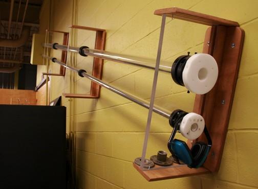
Fini--- It looks like the bearing assembly may be sintered bronze which is usually impregnated with oil. However, that alone probably wouldn't allow for a damped tone arm lowering. The screw on the side of the cylinder and the two disks may be clues. The screw on the side may be used to adjust the rate of the arm's descent once the lever is set to "lower" position. That would suggest that the cylinder would use air as the damping medium. Since the two discs don't have an O-ring between them, I doubt the 0.017" gap between the larger one and the side walls of the cylinder would trap enough air to be useful. That leaves only one logical solution which you found on line---high viscosity silicone-based "fluid". At this point one could argue for coating only the walls of the cylinder with the stuff or filling the cylinder full. If the 300,000 cst is as thick as cold molasses, then I'd opt for coating only the walls---otherwise it might take several minutes for the tonearm to drop. The side screw tells me the silicone is used as a seal between the discs and the cylinder and air is being used as a spring to dampen the rise and fall of the tonearm. The side screw sets the rise and fall time of the arm. I am surprised there is no seal to keep the fluid from leaking out over time. Perhaps the turntable was stored on a hot environment and the original fluid's viscosity changed and it ran out? Lee
-
Pilgrimage pictures!
Arkytype replied to fini's topic in Forum Meetup Planning + Past Klipsch Pilgrimages
Dang! Just my luck. Miz Paula won a set of the S4i ear buds earlier in the festival. Not a bad sounding product. Lee -
Pilgrimage pictures!
Arkytype replied to fini's topic in Forum Meetup Planning + Past Klipsch Pilgrimages
fini, et al-- Later today I'll try to post some pictures I took. However, they are only of the Fair Park venue. As for my impressions of the Pilgrimage---I'm going to reserve those until other attendees post their thoughts. I would like to single out Don (davis419b) and Gary (Waterboy) who went above and beyond to build the "Cornwall facade" for the stage. Lee -
Official Pilgrimage 2011 Info
Arkytype replied to Amy's topic in Forum Meetup Planning + Past Klipsch Pilgrimages
I could use a specially located one for excess flatulence! Of course the fan motor would have to pass the UL explosion-proof rating for hazardous locations. Lee -
Hey Guys and Gals-- I'll be printing the name badges for this year's pilgrimage. If you are planning to attend and have not sent Amy your name, forum name and city by this afternoon, send it to me no later than 4:00 pm central time Wednesday. Otherwise, I'll have a bunch of blank badges you can fill in by hand when you arrive. Depending on what's going on Thursday evening at the Super 8 dining area, I'll have the badges there for you to pick up. I'll be at the park most of the day Friday helping Trey and Jim and then will have the rest of the badges at the Klipsch plant's break room before nine. While the lab will be open, Roy will be absent this year. lclinton@uark.edu See you there! Lee