mboxler
-
Posts
574 -
Joined
-
Last visited
Content Type
Forums
Events
Gallery
Everything posted by mboxler
-
Again, thanks for measuring. I realize the inductance is not important to you. That said, I believe there must be an error with your T2A #1 measurements(?). For example, taps 0 - 1 represent 1/4 of the total turns of the autoformer, and therefore the inductance should be 1/16 of the total inductance. If you were to measure the inductance of taps 0 - 5, I doubt if it's 8.96mH * 16 or 143.36mH. Mike
-
Thank you for measuring! I've been trying to determine if the inductance differences between the 3636 and the T2A are noticeable using stock Klipsch schematics. I'm also considering building an AK-3 to replace my AK-2 and don't know how different the parallel 5mH inductor would be 3636 vs T4A. It probably won't make much of a difference but it's fun to run the simulations.
-
Perhaps I don't understand what this means. I believe you demonstrated that the autoformer itself doesn't change phase. But when used with a series capacitor, as @Deang mentions above, won't the inductance of the output taps increase the phase shift of the circuit, creating a 2nd order high pass to the squawker? A capacitor/l-lad circuit will still be first order. Again, I believe the inductance of the T2A is close to half that of the 3636, so the T2A phase shift increase would be greater. Mike
-
I don't fully understand your predictions, but here are the 3636 and T2A. The 3636 is based on 76mH taps 0-5. The T2A on 44.8mH. Mike 3636.asc T2A.asc
-
I for one have always wondered if the autoformer's inductance is as irrelevant as some have claimed. The spec sheet for the T2A states that the inductance between taps 0 - 3 is 11.4mH +- 15% (at 1000Hz?). My meter measures 8.5mH on one of my T2A's, taps 0 - 3. I'm sure your equipment is better that mine. What is the inductance across taps 0 - 3 on the 3636? Do you have a T2A to measure? I assume your tests were conducted without a series capacitor, therefore the autoformer's inductance would have no affect on the voltage across the driver. It would be interesting to run similar tests with appropriate series capacitors to see how the shunt inductance affects the frequency curve. Thanks, Mike
-
Hey Don Can you post the schematic you have (I believe it's 820928, not 82092B???). The latest schematic I have is revision 900102, which appears to be what you have installed? I'm also assuming the rheostats are variable L-Pads. Mike

-
Although I can't find the AB-3 schematic, I did find a document describing a 162 Hz notch filter across the woofer in the AB-3 crossover. It's composed of a 12mH inductor and a 80uf capacitor, but the series resistor value is missing. I assume the purpose of this filter was to tame this hump?
-
If the inductance of the T4A, taps 0 - 5, is the same as the T2A, taps 0 - 5, then the inductance of the T4A, taps 0 - 3, should be 18.1mH (45.6mH / 2.512). Sorry, I don't have a T4A to verify this. Mike
-
Are you guys just wanting is to test the crossovers to make sure everything is working as designed? If so, all you need are some resistors to replace the drivers, a true RMS meter (I use a Fluke 115), and a sine wave generator (I use an app on my phone). I think I have the ES schematic in LTSpice. Using it, I can determine what the voltages across the resistors should be for a certain input voltage at a given frequency. I do this all the time when testing my crossover designs. It isn't perfect, but clearly shows if I have component issue. If the voltages are right, and the speaker sounds bad, then I know my design sucks. Mike
-
Threads like these kinda bum me out. I can't tell if my capacitors are out of spec because I don't know what the original specs were. Even if I knew the original specs, my DE-5000 LCR meter can't accurately tell me if my capacitors are out of spec.
-
Seems to me that an lpad, unlike an autoformer, will not result in a consistent voltage drop across the driver at all frequencies. This is because the impedance curve of most drivers is not flat. When the driver impedance increases, the voltage across the driver will also increase. Likewise, the voltage across the driver will drop as impedance decreases. Although the variations may be small, wouldn't this be considered distortion?
-
I always thought that those straps were made out of gold-plated tin/steel, not brass.
-
That looks like a B2 crossover. Here's the schematic. Mike
-
What is the crossover frequence for bass in AL-3
mboxler replied to SpeedLimit's topic in Technical/Restorations
Nice build! Your 3619 autoformer is limited to -3, -6, -9, and -12db, but I see no reason why you can't move the tweeter circuit from tap 5 to tap 4. Looks like the DE10 around 3db hotter than the K77, and the load change on the 13uf capacitor isn't that significant. Mike -
What is the crossover frequence for bass in AL-3
mboxler replied to SpeedLimit's topic in Technical/Restorations
I have always based my simulation (LTSpice) on an old post from Bob Crites (RIP). He measured 6.6mH across taps 4-5 of a 3619. Since those taps should equal 29.3% of the total windings, then I came up with 38.38mH across taps 0-4, and 76.76mH across taps 0-5. You probably should recheck my findings 🙂. Mike -
(Quasi-repost) Sub-$1K tubes to pair with Belles?
mboxler replied to GriffinFL's topic in Talkin' Tubes
Autotransformer types and values: T2A(3110A) -3, -6, -9, -12db T3A(3465-M) -6db T4A(3485) -4db T5A(3496) -6db T7A(3504) -10db T8A(3507) -8db T9A(3540) -3db T10A(3542) -9db T11A -12db Looks like the T9A has only one tap, tap 4, which is -3db. It would be the same as a T2A using tap 4, also -3db. -
Better may have been a poor choice of word. In a true 3rd order Butterworth high pass filter, the second capacitor is 3 times larger than the first. 6.8uf is close enough. The 7.5uf would have been fine also, but I assumed you wanted to stay with CSA's. Looking on Al's website, in the Super AA-X section, you'll see how he converts AA to something close to the Universal. Can't make out the second cap value, but I believe it's 6.8uf. Notice also that he doesn't replace the 2.5mH woofer inductor as a part of the conversion. Also, schematic doesn't show the 1.5 amp fast blow fuse. I had it in initially but removed it when I swapped out the woofer inductor. Have fun with your project! What squawker/tweeter are you using? I also made a couple of other tweaks that you may want to try later, but they can be added to the finished crossover easily. Mike
-
Actually the Clarity Cap CSA 6.8uf will be a better choice.. I got the Solen 7.5uf now.
-
Yes, that is the same as the kit I built many years ago. I have, in the mean time, made a couple changes... Replaced the 1.3mH inductor with a 2.5mH for the woofer. Replaced the .2mH inductor with a .15mH for the tweeter. The 2.5mH inductor seemed to tighten the bass. The tweeter inductor swap seemed to smooth out the the top end a little. Mike
-
You pressed submit a few seconds before me. I should have deleted my post.
-
Yes, 2.7 is close enough. Surprised that it is that far off! 4.0uf parallel to another 4.0uf will be 8uf. 4.0uf in series to another 4.0uf will be 2uf. Are you sure they aren't 1uf caps?
-
What is the crossover frequence for bass in AL-3
mboxler replied to SpeedLimit's topic in Technical/Restorations
After further research... Plane Wave Freq. Response 110Hz - 4.1kHz (±5dB) But I've read that in a K-400 it does go up to 6KHz. Not that I know what plane wave frequency response is.🥺 -
What is the crossover frequence for bass in AL-3
mboxler replied to SpeedLimit's topic in Technical/Restorations
I thought the LS5 and AK6 crossed at 4500Hz, around the natural cutoff of the pd-5vh. -
What is the crossover frequence for bass in AL-3
mboxler replied to SpeedLimit's topic in Technical/Restorations
Have you tried inverting the polarity to the pd-5vh? That may create a hump at the crossover that you might like. I've read that the pd-5vh only goes to 4500Hz??? If that's the case, the high pass to the tweeter is around 6000Hz. Seems like there would be a hole there too. -
What is the crossover frequence for bass in AL-3
mboxler replied to SpeedLimit's topic in Technical/Restorations
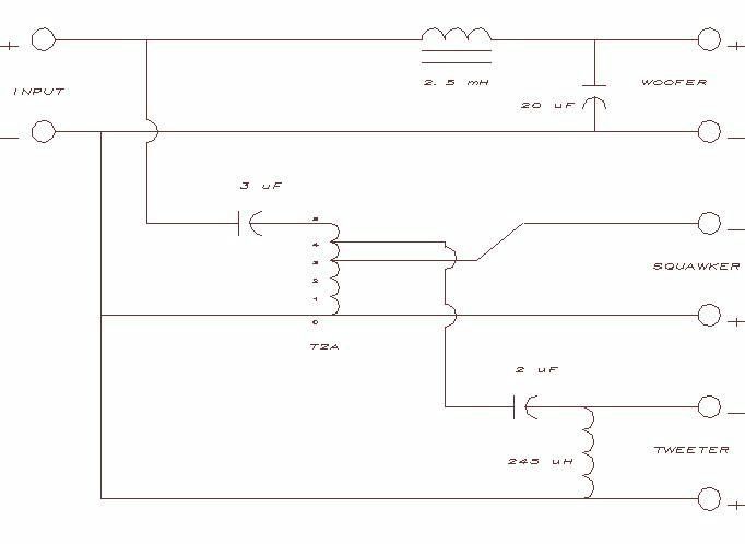
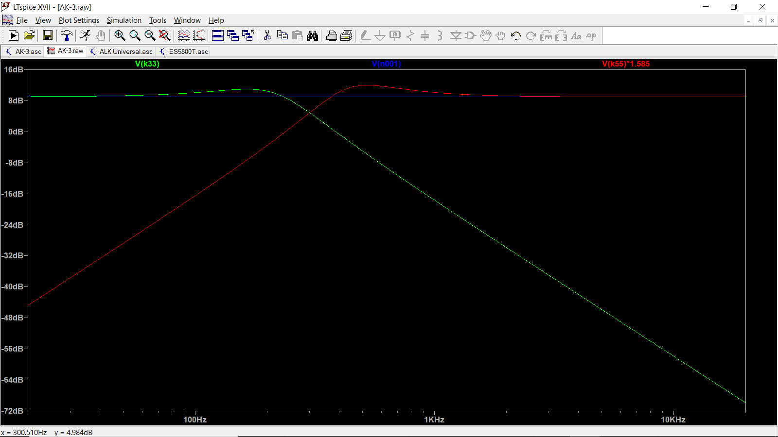
I'm not sure it has a name, so I refer to it as an underdamped second order filter. I assume it was designed for the K-55M driver. Attached is my electrical simulation of the voltages across the K-33E and K-55M. I multiplied the K-55M voltage by 1.585 to account for the T4A's attenuation. As you can see, the adjusted voltages "cross" around 300Hz. Notice that the polarity of the K-55M is not reversed, even though the voltages are roughly 180 degrees apart. Normally this would create a null at the crossover frequency, but I believe the underdamped nature of the filter compensates for that. Then again, I could be totally wrong, but I tend to learn more be being so. Mike