mboxler
-
Posts
574 -
Joined
-
Last visited
Content Type
Forums
Events
Gallery
Everything posted by mboxler
-
Type A replacement caps slightly off spec
mboxler replied to Robbie010's topic in Technical/Restorations
Likewise, the amplifier needs to be designed for this. 2.83 volts into an 11.38 ohm load = .7 watts. However, the only "work" being done is the 2 volt signal across the 8 ohm tweeter, or .5 watts. A capacitor is an open circuit, it does no work. The output transistors of the amplifier need to be able to dissipate the excess .2 watts as heat. In class d amps with single ended outputs, this excess work is "pumped" back into the power supply as increased voltage. At least I think that's right. Sorry, getting way off topic. -
Type A replacement caps slightly off spec
mboxler replied to Robbie010's topic in Technical/Restorations
Although the K-77 isn't a true resistor, for the sake of this explanation let's say it is... The impedance of a 2uf capacitor at 9947 Hz is 8 ohms at -90 degrees. That impedance added to the driver's 8 ohm 0 degree impedance = 11.38 ohm at -45 degrees. 2.83 volts through a 11.38 ohm load = 0.248682 amps. .248682 amps through 8 ohms = 1.99 volts, or -3db. There is a 2 volt drop across the capacitor and a 2 volt drop across the driver. Result. the current through the driver is 45 degrees ahead of the voltage at the crossover frequency. If there is a comparable low pass filter to, say, a woofer, the current through it will be 45 degrees behind the voltage at the crossover frequency. This is what creates the 90 degree difference between drivers in a first order filter. Mike -
Type A replacement caps slightly off spec
mboxler replied to Robbie010's topic in Technical/Restorations
I agree, except for the "half voltage each". The impedance of the 2uf cap will be 8 ohms at around 10 khz, the crossover point. Isn't it true that at that frequency, given a 2.83 volt signal, the voltage drop across the capacitor and the driver will be 2 volts each? Not half of 2.83, or 1.414 volts each. I always knew that the order of series components didn't matter, but you are right! The parallel placement doesn't really matter either. Looks like the impedance of the circuit gets wacky, but the ending voltage across the driver stays the same. Thanks! I learn something new every day. -
Type A replacement caps slightly off spec
mboxler replied to Robbie010's topic in Technical/Restorations
Capacitors in series don't add. They act like resistors in parallel. A 13uf cap in series with a 2uf cap looks like a 1.73uf cap in series with the tweeter. I've never been able to calculate, though, how the autoformer changes that calculation, if it does at all. I'd stick with the 2uf cap. It will be fine. Mike -
Type A replacement caps slightly off spec
mboxler replied to Robbie010's topic in Technical/Restorations
Yep! Think of it this way...the Lpad is now part of the driver. Let's say you want to reduce the voltage to the K-77 by 3db. That would require a 19.4 ohm resistor in parallel with the 8 ohm K-77. Those two resistances in parallel equal 5.7 ohms. Now put a 2.3 ohm resistance in series with that, and you are right back to 8 ohms. The capacitor sees an 8 ohm load. Mike -
Type A replacement caps slightly off spec
mboxler replied to Robbie010's topic in Technical/Restorations
Tweeter Lpad must be next to the K-77, just as the squawker Lpad is next to the K-55. -
Type A replacement caps slightly off spec
mboxler replied to Robbie010's topic in Technical/Restorations
Here's a link. The second post shows the k-55's impedance. Varies all over the place. Around 14 ohm @ 400 hz. https://community.klipsch.com/index.php?/topic/65935-impedance-plots-for-k-55-v-and-k-77-m/ This load dictates the current running through the squawker circuit. The lower the impedance, the more the current, the faster the capacitor will charge. Using the -3db tap on an autoformer doubles the impedance of the squawker circuit. A 13 uf cap is used. Using a -3db lpad designed for the driver will not change the impedance. Current will double. The cap size needs to be doubled so it will charge/discharge at the same rate. A 26uf cap is needed. Hope that helps. Yes, you will need a separate lpad for each driver. The 16 ohm lpad should be fine for the squawker. Mike k55mimp.pdf -
Type A replacement caps slightly off spec
mboxler replied to Robbie010's topic in Technical/Restorations
That's an 8 ohm Lpad. It will work for tweeter, but not the squawker, which is 14 ohms (?). If you make your own 14 ohm Lpad, then a 26uf cap will be needed. With a 16 ohm Lpad, it will be a little off, but now by much. Mike -
Type A replacement caps slightly off spec
mboxler replied to Robbie010's topic in Technical/Restorations
If the lpad you are using on the K-55 is designed to keep it's impedance as is (and just drop the voltage), then you will need a 26uf cap. The 2.2uf tweeter cap should not be an issue. It may measure 2.0 anyway, depending on the tolerance. Mike -
How about a Raspberry Pi / HiFiBerry DAC+ PRO XLR combo? Mike
-
Hey Rick I agree with Bob...you should get the bass bin as close to original as possible. Doing so leaves you with several crossover choices, including active bi-amping! Did you have to cut an opening in the door to install the AK-3 low pass filter? Take a picture of the door and we can help getting your K-horns ready for an upgrade. Mike
-
Belle/Klipschorn extreme slope crossovers
mboxler replied to Erniebear's topic in Technical/Restorations
Go to alkeng.com, navigate to the crossovers extreme slope, and scroll down to "Download ES400 + ES5800 users installation guide". Click on the "Get It" button. The schematics are at the bottom. -
Danny Richie of GR Research just released the first of four videos on the RP-600M. First one details the issues you may be dealing with and his solutions. Interesting before and after measurements, which start 5 minutes into the video. https://www.youtube.com/watch?v=arYwrAtcJZY Second video https://www.youtube.com/watch?v=5ifiz6HrFd0&list=PLUFNGRKZZWXzCt2Syx4yjR4Oy7V-uiePB&index=24&t=0s Third video https://www.youtube.com/watch?v=9MxY5Ne1CK8&list=PLUFNGRKZZWXzCt2Syx4yjR4Oy7V-uiePB&index=25&t=0s
-
The order does matter. The total impedance of the circuit is calculated from the load back to the source (or right to left when looking at a crossover schematic). Think of it like this. 8 / (10 + 4) = .5714... If we swap the 8 and 4 we get 4 / (10 + 8 ) = .2222... This is an oversimplification, but hopefully you get the idea.
-
I'm confused. Are you saying that this doesn't give you balanced connections? https://www.minidsp.com/products/minidspkits/2-x-in-4-x-out-bal Mike
-
I use the 4X10 HD ahead of my LXmini speakers. You will need a Mac or Windows PC to configure. Once configured, no need for the PC. I have an extra 2.5mm 5.5mm chassis mount DC connector I'd be happy to send you. Then the 12 volt PS could be located outside your chassis. Mike
-
If you spread the amp/PS further apart, would one of these fit in between? https://www.minidsp.com/products/minidspkits/2-x-in-4-x-out-bal
-
Is bi-wiring worthwhile? (not bi-amping)
mboxler replied to MeloManiac's topic in 2-Channel Home Audio
I bi-wire as well, and like the results. One of these days I want to re-install the shorting straps with the bi-wire cable connected and see if the sound changes. Now the same speaker cable would be used for both the bi-wire and strapped connection, giving me an apples to apples comparison. Although it sounds scary (and I'm not suggesting you do this) it seems as though you could try the same thing. With A and B on, your two 16 AWG cables would combine into one 13 AWG cable. Mike -
The manual for your Parasound A23+ seems to contradict itself. The balanced input section mentions the 6 dB increase, yet the specifications page implies a 0 dB increase. Total gain 29 dB Input sensitivity for 28.28 Vout Unbalanced 1 V Balanced 1 V per leg This implies that once the non-inverted and inverted legs are subtracted from each other, the resulting single-ended voltage is then cut in half. Confusing.
-
Looks like they do, as long as the caps on the board stay at .015uf. http://www.xkitzconnect.com/files/Linkwitz-Riley-2Way-Calculator.htm
-
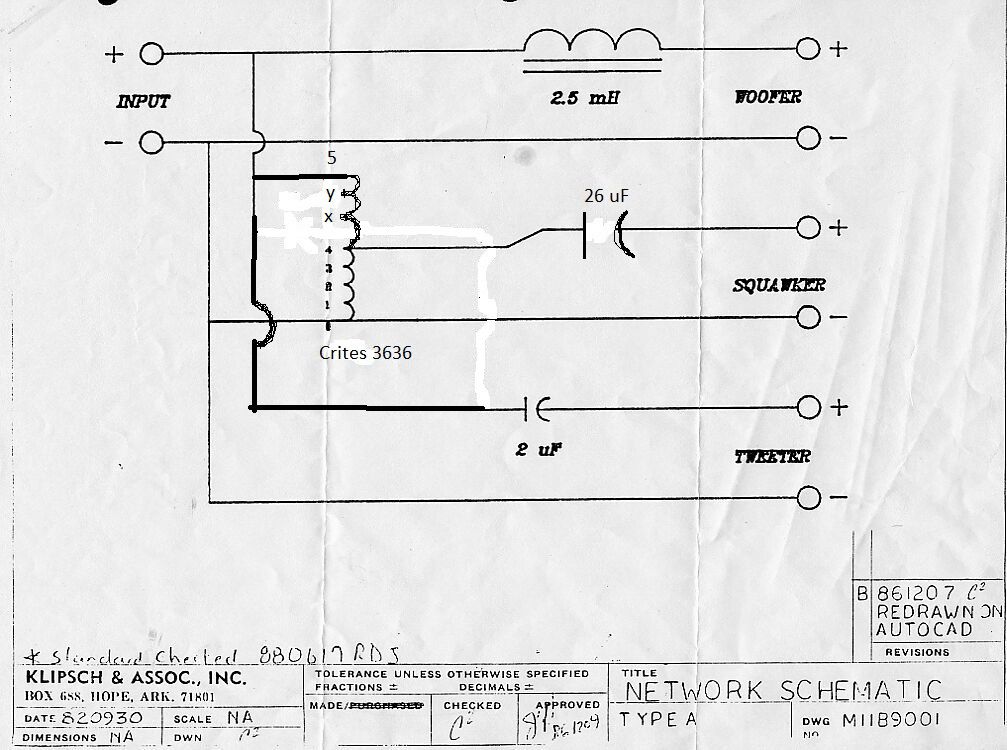
Bumping this 13 year old thread. I'm testing an adjustable Type-A crossover. The attached schematic shows the basic circuit. The T2A will be replaced with a Bob Crites 3636. More importantly, the input wire to the autoformer will be terminated with a female quick connect, and can be connected to taps X, Y, or 5. The autoformer end of the wire to the 26uf cap will also be terminated with a female quick connect, and can be connected to taps 1, 2, 3, or 4. This will allow midrange attenuation of -1 to -12 in 1 db increments, without any change to the crossover frequency (419 hz using a 14.6 ohm resistor in place of the K-55). I built a prototype of the midrange portion of the crossover, and it appeared to work flawlessly. I also tested a 20 hz 6.75 volt signal across 0-5. The voltage across 0-4 measured 4.8 volts...pretty close to the 4.75 volts I expected. It's been said that this circuit will not work well due to the high voltage of lower frequencies. However, the current through the autoformer is identical to the stock Type-A circuit at all frequencies. Is autoformer saturation a product of high voltages, high current, both??? Thanks, Mike

-
A while back I decided to buy ALK's Universal kit. It was my first soldering experience, and even though it looked awful, it worked. Like you, though, I had trouble understanding how it all worked. Forward many years, and I think I finally understand most of it, although I still have a lot to learn. @Deang bumped a thread on inductors. I think that's great, and I think many would like to understand how a passive device that opposes changing current would also act as a low pass AC filter. Likewise, perhaps a thread on capacitors would be helpful. It wasn't until recently that I understood how a capacitor works. Again, I think many would like to understand how a passive device that opposes changing voltage would act as a high pass AC filter. I found the fact that a capacitor blocks DC and allows AC to pass confusing, to the point that I thought they were invented for both purposes. Once I realized that this is not the case (the capacitor was invented long before AC was "invented"), my understanding of crossovers became much clearer. It seems that capacitors are only discussed in crossover upgrades, and then it seems to turn into a discussion on which brand of capacitor is best. I'm sure many don't care about the how's and why's of a capacitor, but perhaps there are many others who do. It might be interesting to discuss plates and dielectrics instead of brand A vs brand B. Then again, maybe not. Apologies to the OP. This was not meant to hijack your thread. Mike
-
This is pretty good. https://en.wikipedia.org/wiki/Bridged_and_paralleled_amplifiers It was hard for me to understand the concept that each of the bridged amps "sees" one half of the speaker's impedance, until I worked backwards from a mono amp. 1) A single-ended mono amp with a +-50 volt power supply delivers the same power to an 8 ohm load as two bridged amps with a +-25 volt power supply. 156 watts. 2) If the two bridged amps combine to deliver 156 watts, then each amp must deliver half the power, or 78 watts. 3) Each amp is applying 17.7 volts rms and 78 watts to it's side of the 8 ohm driver. 4) Ohms = Volts squared / Watts. 17.7 squared / 78. 313.3 / 78. 4 ohms. Not sure if that's the correct explanation, but it worked for me.
-
Sorry, but can't seem to let this go. The 100 volt comparison is misleading. It's true than bridging two amps with a +- 25 volt power supply can deliver the same voltage across a load as one single-ended amplifier with a +- 50 power supply, but it's not the same circuit. Again, each of the bridged amps (+- 25) can apply a 17.7 volt rms signal to it's side of the load, with the second amp's signal inverted. The single-ended amplifier (+-50) can apply a 35.4 volt rms signal to one side of the load and will apply zero volts to the other side. Notice I said "can" apply. The D75 has a voltage gain of around 20, so a .5 volt rms input signal will be amplified to 10 volt rms to drive one side of the load. 10 volts rms equals +- 14.414 volts. Since the power supply can deliver up to +- 25 volts, your good. The extra volts are not wasted or lost, they are just not used. A 1 volt rms input signal, of course, will be amplified to +- 28.29 volts, and clip. Likewise, just because an amp can apply a certain voltage doesn't mean it supply the current. That's why the D75's 4 ohm rating isn't twice the 8 ohm rating.
-
Your Crown D75 is a perfect example of current limiting. It's 40 watts into an 8 ohm load, but 55 watts into a 4 ohm load. This tells me that it's limited to 3.7 amps per channel, not the necessary 4.5 amps required for 80 watts. Your loaded +- 25 volt supply equates to 35.35 rms volts bridged, more that the 30 volts required for 110 watts into an 8 ohm load. If the doubling of the voltage when bridged concept is still confusing, consider this. When driving a speaker single-ended, when the + side of the speaker has +25 volts, the - side has 0 volts, a 25 volt potential difference. When bridged, the + side of the speaker has +25 volts, the - side has -25 volts, a 50 volt potential difference.