MechEngVic
-
Posts
580 -
Joined
-
Last visited
Content Type
Forums
Events
Gallery
Everything posted by MechEngVic
-
Then it is you I have to thank for exposing me to the idea of screen stoppers. If you check out the thread I started at the Dynaco forum by the same name you can read the advice I'm getting which is sounding pretty good so far.
-

-
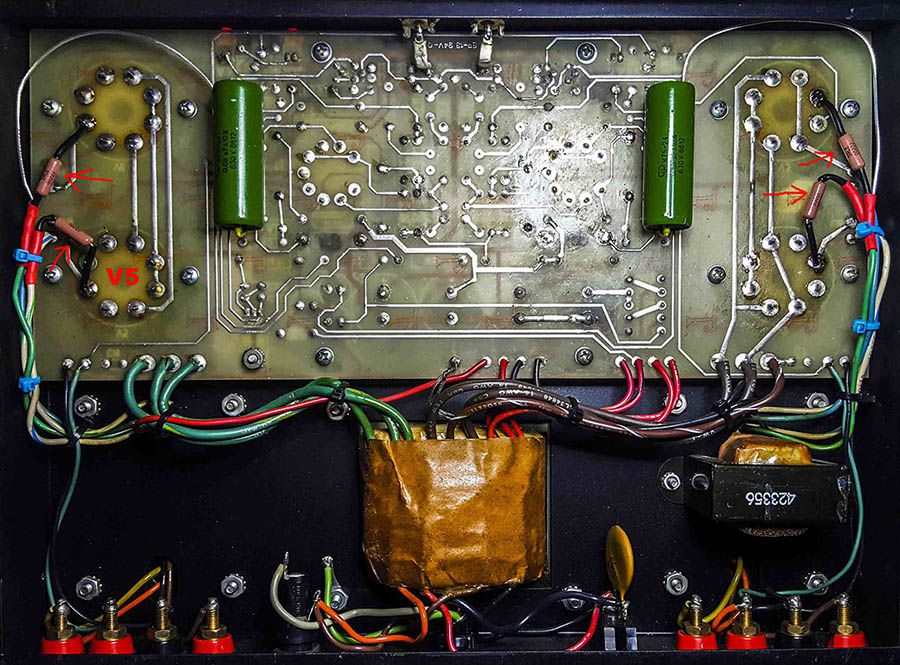
Thanks dirtmudd, I actually have screen stoppers installed, I installed them after the first time V5 blew a tube (100ohm). V5 is the only position that is having this problem. I have owned the amp since 1992. It gave me several years of trouble free service before tubes wore out. At the time I replaced them one-at-a-time with the cheapest el34 I could buy at the guitar shop. At that point the bias resistors began blowing regularly, and shortly after an unknown resistor blew and I lost the right channel and I pulled the amp from service. Last year, I rebuilt the amp, replacing every resistor and capacitor. After several dozen hours of service and many on-off cycles, V5 arced and red-plated. Then I replaced the original tube sockets and added the screen resistors. I replaced the tube with a matched one. While V5 no longer red-plates, it is still arcing, it has done it twice since the first time for a total of 3 times. Each time I have replaced the tube with a new matched one.
-
Yes sir, C25 is a new 600v Russian PIO cap. If I get desperate, I might replace them all again, maybe 630v Solen film and foil caps. A set of the Solens cost about the same as the matched pair of tubes this problem has eaten already.
-
I also wanted to add that the tube arcs during warm-up, not right away but several seconds to over a minute into it. Arcing during warm-up is the failure that is happening. It happens once, then it doesn't arc for several hours of use and several on and off cycles. Then it will do it again and again with increased frequency. Now that I see the pattern, I don't let it happen more than a couple of times before I replace the tube. Then all is well for many dozens of hours and many dozens of on and off cycles before it does it with the new tube.
-
I wanted to add that the output transformers are A470's
-
I have a Dynaco ST-70 Series II amp. The V5 position keeps blowing tubes. It's not a connection or solder issue, they have been gone over multiple times and tube sockets have been replaced. This has happened before and is happening after a major rebuild. The only thing not new is the transformer. Voltages are all within spec and so is the bias. Can an old beat up output transformer cause a tube to go bad?
-
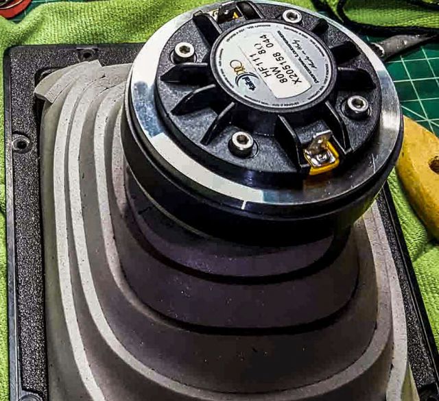
Would like to hear your impressions once you've tried them. I put the Crite's in my KLF-10's and I liked their sound better than the stock diaphragms.
-
Is all good when we make a change and it makes things sound worse, we can just put things back how they were. But when we make changes and they sound good too? Yes, quandry indeed. I was surprised to find out just how much a subwoofer can affect the sound of your mains. They don't just add low bass, they can clash with your mains to cause nulls at higher bass frequencies, and they can affect how high frequencies sound. You have the sub's gain, it's crossover frequency, it's phase, and it's position; all things that can add to, or take away from, that imaging you're loving right now. Sounds like a good "corona project".
-
A55g and need for an HF crossover point mod?
MechEngVic replied to Alexander's topic in Technical/Restorations
I was aware these were from another post. When you measure the whole speaker at the same time you might see this kind of dip. The dip is not only due to the mid driver itself but the interaction of the mid and woofers. Even a cell phone app will show you if there is a dip or hump big enough to worry about. -
DIY Wooden K400 Horns - Help Connecting Driver?
MechEngVic replied to Robbie010's topic in Technical/Restorations
OOPS. -
DIY Wooden K400 Horns - Help Connecting Driver?
MechEngVic replied to Robbie010's topic in Technical/Restorations
AWESOME!!! -
A55g and need for an HF crossover point mod?
MechEngVic replied to Alexander's topic in Technical/Restorations
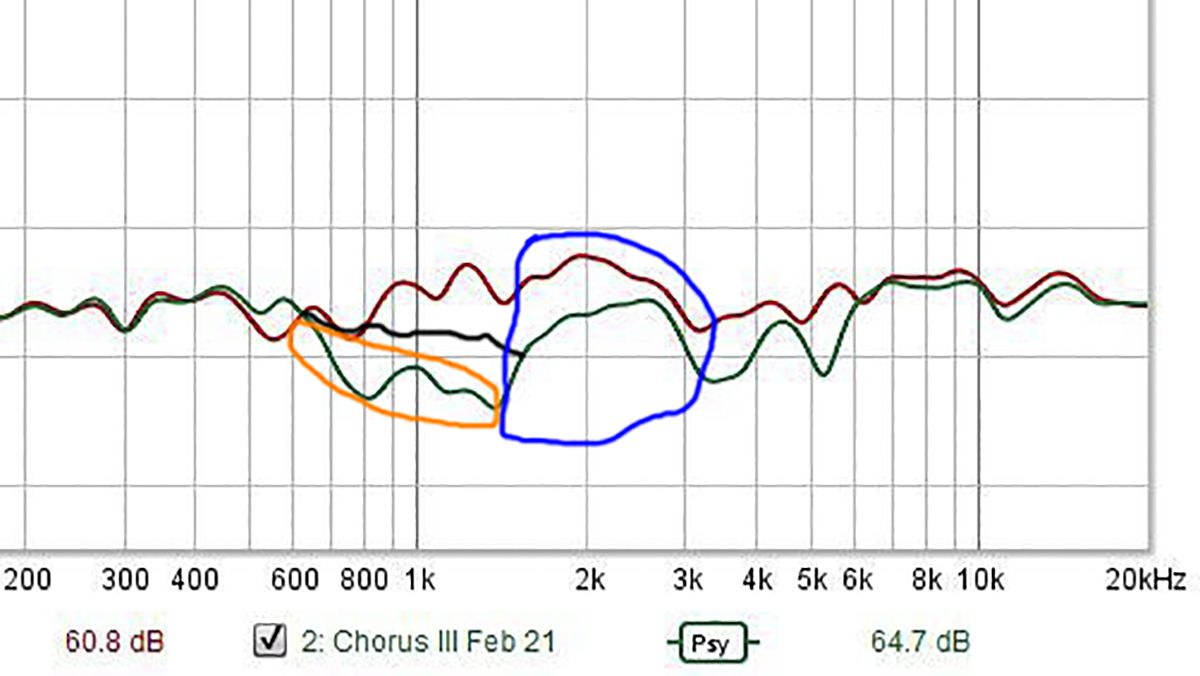
The blue circle represents the "hot" part of the mid, that 1500-3000hz hump, it's what give Klipsch horns their beautiful midrange forwardness, that midrange sound that is so addictive and unique compared to other speaker brands. The problem is that hump can be too hot in some setups. But you don't want to eliminate the hump you just want to tame it a bit. This is why I recommend that instead of changing inductor and capacitor values for the horns (for the woofers it's ok), you use resistors. Properly placed resistors can lower the curve without changing its shape. In this graph, the green curve (the blue circled part), the hump has been lowered but the curve between 600 and 1500hz is an issue (the orange circled part). I drew in a black line to illustrate a better position of the curve at that range; while not eliminating the 2k hump, just making it a bit smaller. If you run into the same issue, and you want to keep the mid where it is, you can add capacitance to the high frequency roll-off of the woofers, allowing them to roll off a bit higher and cover those overly tamed frequencies between 600 and 1500hz.
-
A55g and need for an HF crossover point mod?
MechEngVic replied to Alexander's topic in Technical/Restorations
The dip in the second graph, green line, starts at the crossover point between the woofer and mid. I wouldn't doubt that entire dip is due to the interaction of woofer and new mid driver. Your setup might respond similarly. The crossover of the Chorus ii is almost identical to the KLF-30 in the mid and tweet, so I bet you don't have any issues at the mid/high point, but will have issues at the woofer/mid handoff like in this graph. It almost seems like the a55 is less sensitive than the k52, at least at the low end. The good thing is you have some breathing room with that 22ohm resistor (you can give the a55 more current by lowering the value, maybe 15ohms), and you can ask the woofers to do a few more Hz by raising the value of the 97mf cap (by adding parallel caps, maybe 3-6uf), those woofers can certainly handle it. None of these changes should mess with your impedance too much either. -
I enjoyed your first post(s) and was impressed by many of your observations. But your self-righteousness started creeping in right along with your smarts (just like in the first words of this, your "last" comment). I'll be the first to agree we're not all saints, but you.... You take the cake. The apparent level of intelligence mated with the staggering level of immaturity in you is alarming. To first tout the virtues of a set of speakers, and then with the same mouth, insult the man who made them what they are, because he questioned your demonstrably false claims about sealed vs open cabinets and about a speaker you haven't even heard...?!?!? You've caused me to begin some serious soul searching in order to weed out any behavioral similarities.
-
A55g and need for an HF crossover point mod?
MechEngVic replied to Alexander's topic in Technical/Restorations
I hadn't noticed that. Makes things easier. I'd probably leave the auto transformer in its factory setting and if anything, adjust the 22ohm resistor by a few ohms either way if needed. Maybe you'll get away with leaving the mid circuit as is and only slight changes to the tweeter if that. Simple sweep measurement from your sitting position will show anything obvious. -
A55g and need for an HF crossover point mod?
MechEngVic replied to Alexander's topic in Technical/Restorations
I don't know about changing the color theme of X-Sim, I'd like it dark too! I'll check next time I get on. As far as the autotransformer goes, they are similar to an inductance divider but with much different impedance behavior. As of now I don't know how to model one. -
A55g and need for an HF crossover point mod?
MechEngVic replied to Alexander's topic in Technical/Restorations
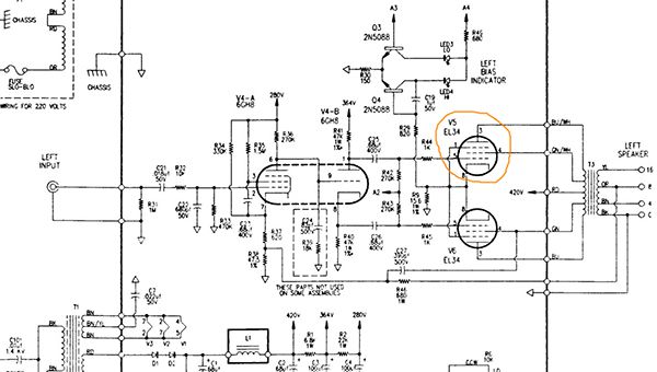
A driver is going to respond to a full bandwidth signal in a particular way based on how it is built. Tuning the signal doesn't really change the "sound signature" of the driver, rather, a tuned signal changes the "volume" of specific parts of the signal that the driver will see. The driver will tend to keep its sound signature, that's why the a55g will sound different (many say better) than the k52 no matter what changes you make. Now, if the a55g begins to roll off at 6300hz, you'd still have a lot of information coming through at 7000hz with a full signal. What you need to find out is how much "volume" the KLF-30 crossover is giving the driver at 7000hz. It may be less or more than you want since the KLF-30 crossover was meant to tune the k52. I would model the drivers and crossover in X-Sim (or similar software) and compare the crossover's frequency response curves using the same crossover values but switching the mid driver FR and Z between the a55 and k52. It won't give you precision but it will show you how the crossover treats each mid driver. If the graph shows more dip at 7000hz with the a55 then with the k52, you may be able to make changes to either the tweeter or the mid part of the crossover. -
We'd love to see that crossover diagram... just sayin.🤩
-
You can learn a lot about how your system is grounding by taking a long piece of wire and touching it between two pieces of equipment or ground leads. Use it as a sort of probe. Connect one end of the wire to a chassis and then probe ground points of other components or cables (GROUND LEADS OR CHASSIS ONLY). Use your amp as the initial grounding point.
-
No change to inductor or capacitor values so frequency response curve stays same shape, only high frequency drops 6-8 dB's, very little change to impedance, and it drops the crossover frequency a little bit. If highs are "annoyingly' high, a 3dB cut won't do it.
-
https://www.ebay.com/itm/L-Pad-50W-Mono-1-Shaft-8-Ohm/221540014845?epid=1501513264&hash=item3394d05afd:g:t1EAAOSwPe1UBzpA
-
I'm not justifying any of the previous comments, but I will say that A/B testing works best when there are obvious differences of sound in two sources. The brain, by default, looks for similarities; symmetries, so your brain will want to highlight what sounds the same in two subtly different sound sources. Subtle differences are best found by listening to either source for a period of time, same set of music pieces, and making notes of what stands out to you in each source, then comparing notes.
-
I like it!
-
That almost looks like plywood layers sandwiching a particle wood center.