captainbeefheart
-
Posts
1422 -
Joined
-
Last visited
Content Type
Forums
Events
Gallery
Everything posted by captainbeefheart
-
Forte Model 2 Class A preamplifier
captainbeefheart replied to captainbeefheart's topic in Solid State
Thanks Chris. I am reading some good things about it so I'll most likely take it. I can't resist practically free gear, I know it will chew up a day of time for me to fix his amp but I think it might be worth it. -
I was hoping someone here has had some experience with a Forte Model Class A preamplifier. Someone local asked if I would take it in trade for getting their McIntosh 2100 up and running. I was told Nelson Pass had a hand in the design and that the unit is held in pretty high regard for the price. I suppose if I don't like it I could always sell it as I don't really need it. I am thinking I might take it and help the guy out. What say you?
-
Help--Need a Harman Kardon 430 tech.
captainbeefheart replied to JohnW's topic in 2-Channel Home Audio
oh ok lol yes that explains it, sorry I should be more specific in troubleshooting tips for people and not assume they do this stuff all the time. You can't measure a resistor out of circuit and read a voltage, that would be wild. Out of circuit just check the resistance value to make sure it's what it should be, in this case 8.2 ohms. The troubleshooting tip I was trying to explain was for when you get done troubleshooting the regulator board and it's all fixed or working properly and you install it back into the amplifier. When you then go to power the amplifier back on is when you want to do what I am suggesting. We use ohms law all the time to figure problems out. I = V / R I = current V = voltage R = resistance No voltage across a resistor out of circuit because there is not current. By looking at the wattage rating of R9 and the current rating of the fuse I can extrapolate roughly how much current that should be in that circuit. To measure the current easily we use ohms law and instead read the voltage across R9 which since we know the resistance value of R9 we have two variables and can solve the equation to find the third. When you power the amplifier on while watching your meter reading voltage across R9 and you see it rise to 2 or more shut the amp off to protect it from doing any more damage and burning R9 up again. Plugging 2v into the equation we get. 2 / 8.2 = .243 Why do I think this is amount of current shows there is a problem? Like I said the wattage rating of R9 being a 1/2 watt resistor. Let's figure out power through the resistor. P = I * V P = power in watts I = current V = voltage .243 * 2 = .487 so .487 watts The 1/2 watt (.5) resistor will get very hot running like this but it's within it's ratings. Most likely the circuit is pulling less than this amount but we can easily say that there shouldn't be more than 243mA flowing in that regulator circuit just through reasoning, deduction, and a little math. -
Help--Need a Harman Kardon 430 tech.
captainbeefheart replied to JohnW's topic in 2-Channel Home Audio
That's what you read with the amp on? Is the fuse blown? What you want to do is read the voltage across R9, that's one test lead of your meter on each lead of R9. Turn the amp on and watch the voltage, if it passes past 2v shut the amp off. It's a way to see if the circuit is pulling too much current before doing any more damage like burning R9 up or blowing the fuse etc..... -
Lascala amp requirements?
captainbeefheart replied to Allhartfidelity's topic in 2-Channel Home Audio
That's what most people would think is the trick but that's not it. I incorporate positive feedback in some of my amplifiers that would bring a SET amplifier output impedance of maybe ~1 ohm and a damping factor of ~5 to an output impedance of .08 ohms and a damping factor >100. So solid state like damping but the finesse of a SET. The SET niche is a small one and typically builders like to copy old designs and use fancy boutique parts to try and improve the sound the wrong way instead of going back to the drawing board and changing the circuitry to improve some of the shortcomings of the topology. I am all for quality transformers and that's where most of the money should be invested into but they can only bring you so far since they are just impedance converters. -
Help--Need a Harman Kardon 430 tech.
captainbeefheart replied to JohnW's topic in 2-Channel Home Audio
Instead of continuing to blow resistors keep a volt meter connected across R9 to monitor how much current is being pulled through it, as I mentioned above anything more than 2v across it there is a problem. If everything on the regulator board is fine the problem must be on the load side where +B3 feeds. Looking at the schematic it looks like it powers the AM/FM circuits so check that section also. You must have a dead short somewhere like a bad transistor, diode, or capacitor. -
Help--Need a Harman Kardon 430 tech.
captainbeefheart replied to JohnW's topic in 2-Channel Home Audio
Are you reading .3v with the meter or .692v? I can't tell if you are subtracting .692 from 1 and coming up with the .3v, that's not how it works. If when you connect red probe to base (pin#3) and black probe to either emitter or collector and your meter settles down to reading .692 then that looks like a good reading and I would say it's fine. I typically remove and test out of circuit. If this was my amplifier or needed to repair it I would take that board out and remove D6, D7, and Q1 and test out of circuit. Then I would remove C1, C3 and C4 and test those but more likely since they are out just replace them due to age. +B3 powers the AM/FM circuitry so look at that also and make sure there are no shorts there. Once everything is checked or replaced on the regulator board then carefully power it up with a voltmeter across R9. Since we know they are using a 1/2 watt resistor I would expect current draw to be quite low, maybe 100mA-200mA. So during normal operation you might see around 1v drop across R9. If when you first power it on and you see the voltage across R9 creep up to 2v or more shut it down there is a problem. A 2v drop across R9 is 487mA and you know the 1/2 amp fuse is going to blow soon. -
Lascala amp requirements?
captainbeefheart replied to Allhartfidelity's topic in 2-Channel Home Audio
You can get away with flea amps as La Scala's are very efficient, it all depends on your room and listening requirements. Although not as difficult a load bass wise compared to a Cornwall, Heresy, Forte etc.. many SET amps may come up short for control and power but it really depends on the circuit. I'd say if you have a SET amp with either high enough load impedance for better damping or better some global feedback it will work quite well, so again it comes down to the actual circuit and good design. Contrary to what people think you can actually have a SET amplifier with damping factor of solid state, that's the magic of negative output impedance from some circuit trickery. Overall they are an average speaker to drive, you can get away with more amp options vs the other speakers I mentioned but a good performing amplifier is always best in my book and not just 'good enough'. -
I see you used a separate filament transformer for your heater supply. I imagine your power transformer has 6.3v windings? If so it should be an easy conversion.
-
Great amplifier to try the 4P1L out in. I have tried 6V6 in triode mode and it is pretty good I agree but once you compare it to a 4P1L you'll never look back. There are two problems though, you'll need different sockets and since the 4P1L is a directly heated cathode you may want to rectify your 6.3Vac to DC and regulate down to 2.1v, or as I do with my 6.3v supplies is use current source instead of a voltage source and set it around 650mA to power one 4P1L per channel. That's with the filaments in parallel which is better. Heater requirements per tube is: 2.1v at 650mA 4.2v at 325mA
-
Help--Need a Harman Kardon 430 tech.
captainbeefheart replied to JohnW's topic in 2-Channel Home Audio
Most transistors come in standard packages like TO-220 or TO-3 etc...... which have a standardized pinout. If you are ever in question look up the datasheet, if you are designing a circuit you should be looking at the datasheet anyway. I don't expect everyone to know this stuff but for future reference. For the 2SC1212 the pins are ECB from left to right (123). Put the red test lead from your diode tester to the right most leg which is the base (pin#3) and touch the other two pins (emitter and collector) with the black test lead to see if each has a .6v diode drop. Flip the leads around and put the black lead on the same base pin, furthest to the right (pin#3) and you should have zero continuity with the same test, infinite resistance, open line (OL). It's the same way you would test a diode, in one direction with the meter you will have a .6v diode drop, flip the leads around and you shouldn't have any continuity. Good luck -
Help--Need a Harman Kardon 430 tech.
captainbeefheart replied to JohnW's topic in 2-Channel Home Audio
I guess first just check for shorts, if your resistance meter beeps continuity between any pins it's junk. Transistors are current controlled devices. An NPN will have normal .6v diode drop between base and emitter. This small amount of current allows a much larger amount of current to flow between collector and emitter. The collector will also have a normal .6v diode drop between base and collector. Most multimeters have a diode test setting. Place red probe on the base pin and touch each emitter and collector pins with the black probe, you should see the normal .6v drop for both base to emitter, and base to collector. Think of a PNP transistor as the diodes reversed. The 2SC1212 is an NPN so don't worry about testing a PNP type. -
Help--Need a Harman Kardon 430 tech.
captainbeefheart replied to JohnW's topic in 2-Channel Home Audio
Move on to that transistor bolted to the heatsink right next to the bridge rectifier. Use a diode tester and check the transistor base-emitter and collector-base. Check it for shorts also. -
It's the paper capacitor I circled in this picture. You can probably just snip one lead and if it doesn't cause any noise issues just leave it. Or go to the link I posted above and purchase one of those Y safety capacitors and replace it. Y capacitors fail open and are designed for this specific application. They differ from X capacitors which go across the line to neutral and fail short. So make sure you get a Y rated safety capacitor and you can sleep at night knowing your amp won't kill you.

-
Help--Need a Harman Kardon 430 tech.
captainbeefheart replied to JohnW's topic in 2-Channel Home Audio
No problem good luck -
Help--Need a Harman Kardon 430 tech.
captainbeefheart replied to JohnW's topic in 2-Channel Home Audio
EDIT: I found where it is and what it does. It's 8.2 ohms 1/2 watt It is in series after the fuse from the transformer to the bridge rectifier D6 on "rectifier board A". Check the bridge rectifier D6 and also check the regulator transistor Q1 for shorts. Also check D7 the reference zener diode and all the capacitors around Q1. -
Yes thanks. If you can solder it should be a pretty easy repair. With a polarized plug wire the hot which is the smaller prong of the two to where I circled in red. Then solder the neutral which is the larger/wider prong of the plug to where I circled in green. That's it simple as that.
-
Distortion is a change of the waveform between input and output, any difference will be measurable and quantifiable. Not all distortion is equal, you can view them to music theory as a parallel. The second harmonic is a musical octave, the third harmonic a 12th, etc.. These are known as musical intervals and a form of harmony. If you want to break things down to what is natural, sound waves in the air to the ear is expressed with equations in fluid dynamics. In laymen terms the high pressure peaks will travel faster than the low energy troughs which leads to a non-linear transfer and subsequent even harmonics. So one could say even harmonics are more natural vs odd harmonics. This is a very well known concept and why SET amps sound nice due to the even harmonics. In guitar distortion world some prefer linear distortion which produces a more aggressive odd harmonic content. Square waves produce odd harmonics for example. Typically you don't want distortion but low level even harmonics are going to be much more benign and natural compared to odd harmonics.
-
It's hard to see in the picture but it looks like that .01uF capacitor on the mains to chassis is a one of those yellow print Sprague paper capacitors. They do not hold up to time very well and many that I test are very leaky, it's the last thing I would want connecting the hot to the chassis as eventually it will be able to leak enough current to kill you. For inquiring minds the red paint 'difilm' Sprague capacitors are very high quality and almost all I test are still functioning fine and do not leak current. Pyramid paper capacitors were black molded with yellow paint also and look like that, they too are usually not in good condition and not safe for that application especially at it's age. I highly recommend removing it and replacing it with a safety Y capacitor. https://www.digikey.com/en/products/detail/kemet/PME271YB5100MR19T0/3790120 EDIT: Looking even closer at the picture I can clearly see the 820k resistor connected to the left side electrode of the extra power plugs on the back of the amp, that's the neutral side. The right side is hot, which should be switch side and connected to the capacitor.
-
Yes since they used a non-polarized plug it will not cause any damage either way but one should exhibit less noise which is the way you want to wire it up. So the best way to do it is connect it whichever way has less noise. I typically see the neutral with a resistor to chassis and the hot with a capacitor to chassis. If it was wired in reverse you would have 120v on the chassis if you left it plugged in with the power switch off. The 820k resistor will limit the current to 146uA which is not enough current to kill you but what if that resistor failed short? Then you would have 120v with no current limiting ability on the chassis before the fuse which is bad. The branch circuit feeding the receptacle the amp is plugged into is a 15A circuit breaker which is typically the smallest you'll see, well 15A is plenty enough current to kill you. The only way it would be safe would be relying on a GFI receptacle.
-
Looking at the schematic the power switch also energizes the accessory receptacles on the unit and also connects a .01uF capacitor to ground. The other side is fused and has a 820k resistor going to ground before the fuse. I would wire it up with the hot on switch side and the neutral on the fuse side. Before committing to this maybe check with a scope to see which connection has the least noise, my professional opinion would put be like I said, hot on the switch side which is the little electrode and the neutral on the fuse side which is the large electrode on a polarized plug. Replace the .01uF capacitor with a safety rated Y capacitor.
-
What is the exact model of the Fisher?
-
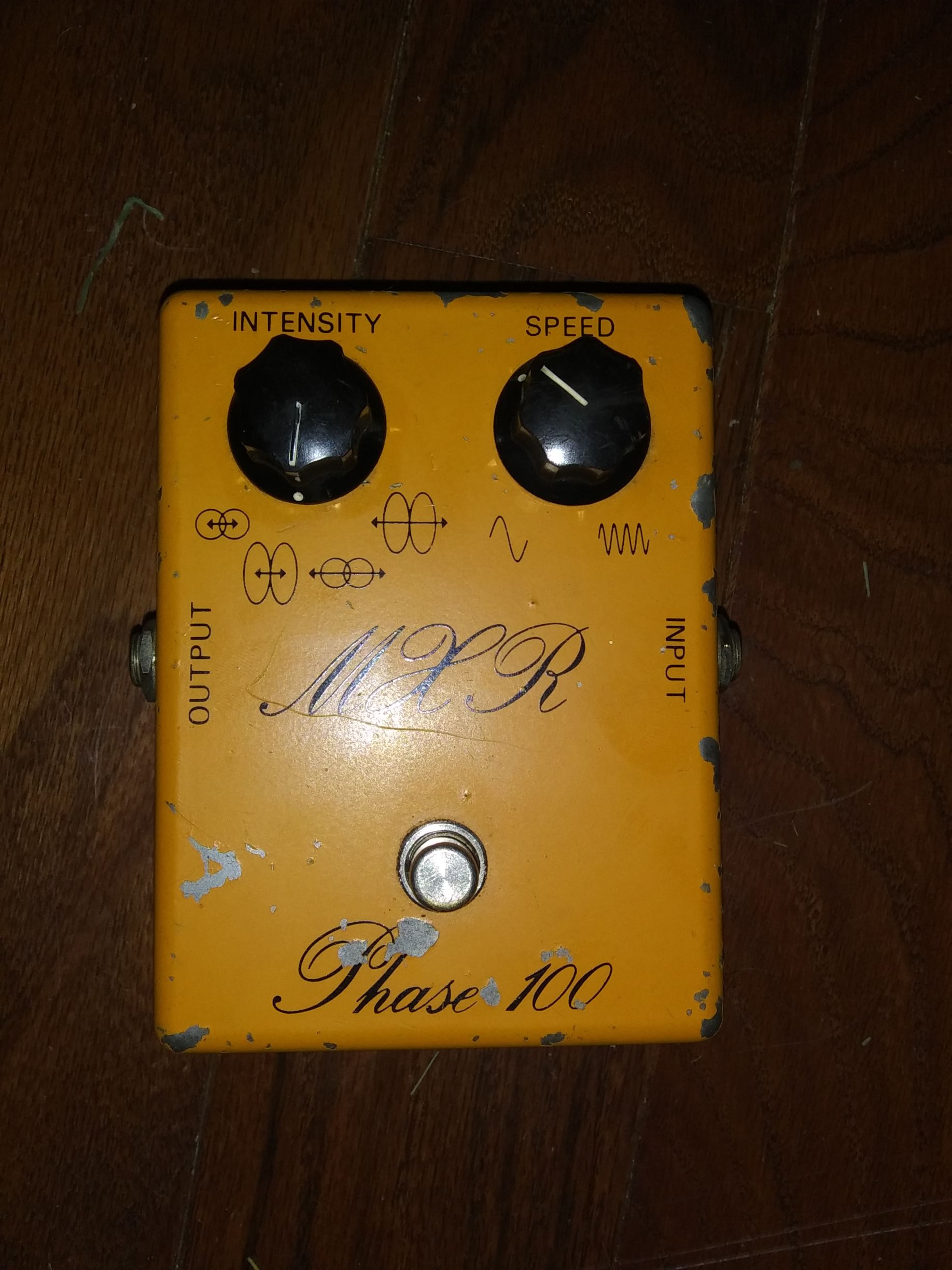
He must still have one of these also. I remember getting this original script logo MXR Phase 100 over 40 years ago. David Gilmour uses it during "Shine on You Crazy Diamond" after the organ intro part where he plays those four notes that ring on while the drums build and the whole band kicks in. The sound is just incredible. I have had it so long because it just has such a lush tone to it and the settings are very versatile. I highly recommend. The other 45 and 90 are good too but this one is the best.
-
If you like weird sounds one of my all time favorite analog pedals is the Fuzz Factory, it has a bunch of knobs connected to pots to change the operating points and gain of the transistors. It can make a ton of very unique sounds. I use one setting called 'atari' or whatever that sounds so unique I use it for some progressive jazz solos and it's just off the wall amazing sounding, like vintage 80's video game soundtrack tones that are out of this world.
-
You're actually in my neck of the woods. If you ever need any help with anything let me know or I would be more than happy to lend you an amp of mine to listen to for a little while.