captainbeefheart
-
Posts
1422 -
Joined
-
Last visited
Content Type
Forums
Events
Gallery
Everything posted by captainbeefheart
-
There is a big assumption there that they only used an aluminum electrolytic only because of cost. Us engineers learn things, many times the extra ESR is chosen not because of price but because the specific properties give an added advantage. In this case there is going to be a resonant frequency around ~355Hz from the filter, the ESR of the cap helps dampen the oscillation and flattens it out. Now if you do want to use a film capacitor for longer service life you would then have to add the extra resistance into the circuit to dampen it. Regulator circuits same thing, choosing decouple capacitor type has the same issue, too low ESR it's unstable, too high same thing so you end up choosing a tantalum. For example I was designing a regulation circuit the recently and the 6v low dropout regulator datasheet went into great detail about this in order to get the best results with their product. Some guys just slapping together a product for market and doesn't do his homework the device ends up not having a short service life. Happens far too much. The end result is all that matters, you happen to use a film cap in that position and ended up liking the way it sounds and your happy it's a win.
-
Dissipation factor or I was calling tan (tangent, loss angle) same thing is only .017 on your 80uF electrolytic capacitor? Wow that's a really high quality lytic!!! What brand and line of cap is this I wouldn't mind taking a peek at the datasheet too.
-
FWIW ESR = Xc * tan If you are observant you will notice companies like Rubycon or NIchicon will not say ESR but will only give the loss angle which is .2-.25 throughout any voltage rating or capacitance value (Rubycon datasheet). As you see in the Illinois that ESR is all over the place because it depends on Xc or reactance so the capacitance value dictates ESR, the lower the capacitance value for a given frequency the higher the ESR will be. For the Illinois capacitor we can figure out the loss angle easily by: 3.97 / Xc Xc = 13.26 for a 100uF capacitor at 120Hz 3.97 / 13.26 = .299 So the tan or loss angle is .299 for this line of capacitors. You can figure an 80uF capacitor at 355Hz with a loss angle of .299 will have an ESR of; 5.6 * .299 = 1.67 ohms Close to my 2 ohm guess before. Some cheap caps have a higher loss angle and so ESR can be as high as 5 ohms or higher depending.
-
Here is a datasheet from Illinois Capacitor for their electrolytic caps 100uF 350v rated capacitor has an ESR of 3.97 ohms

-
The resonance should be ~355Hz so measre ESR around there. Typical datasheet for general purpose electrolyics state 2 ohms for ESR at 100Hz, they test at low frequencies because full wave rectification is 100Hz/120Hz.
-
Found this about the 885; "Test conditions: 100 Hz, 120 Hz, 1 kHz, 10 kHz, 100 kHz (886), 1 Vrms, 0.25 Vrms, 0.05 Vrms" At least it doesn't just test at 100Hz like many people are using to check their crossover caps which is useless. You have the ability to test the 13uF cap with the 1kHz setting and the two 2uF caps 10kHz, that will give you a better idea how they are doing in that application.
-
Why do you not use an Aluminum electrolytic capacitor for the woofer circuit? If you notice in simulation with a "perfect" capacitor you will get a resonant peak around 355Hz, the ESR of the electrolytic will flatten it out. Also at what frequency does your tester test ESR at? It's important to note that ESR will change with frequency so it's important to test the capacitors at the frequencies to which is important for the application. E.g. Tweeter caps test 5kHz and up.
-
Another reason to use an electrolytic capacitor for this application. Go back into your simulation and add typical series resistance from an electrolytic capacitor, 2-5 ohms and you will see that 355Hz resonance flatten out with the 80uF capacitor.
-
When paralleling capacitors remember they too have parasitic properties like inductance, depending on these variable you may end up with a resonance somewhere you don't want it, like in the tweeter network.
-
I suppose I shouldn't make blanket statements. I should have said for an average speaker with average speaker wire length and gauge. Ok so 3 meters of 14awg is about ~.0246 ohms Klipsch Heresy will dip to ~4-5 ohms at certain frequencies 4 / .0246 = 162 With this specific "scenario" you'll always tap out at a maximum DF of 162 no matter if the amp is advertised as having a DF of 200, 500, or 1000. You can of course run your amplifier on a stand or rack directly next to the speaker as close to it's input terminals as possible and then you can actually achieve a higher DF. But is that best? I like to have a damping control because I have found "maximum" damping isn't always best. Makes sense, over damped systems will achieve 0 amplitude of transient slower than one that is critically damped. Finding that specific resistance value is much easier when you can adjust it.
-
The second you connect the amp to your speakers with speaker wire all that damping factor is useless and you're right back down to where everyone else is.
-
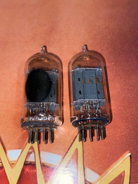
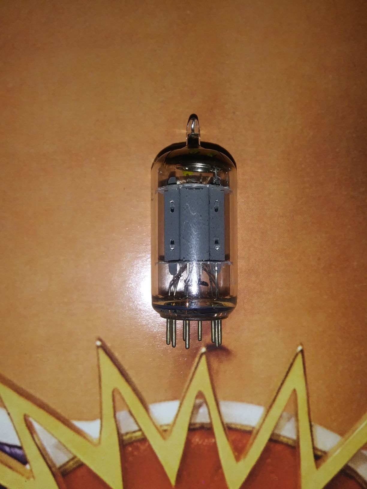
The pair is $50 including priority shipping with insurance. Which breaks down to $20 each These were much tougher to match up compared to say Telefunkens or Amperex, probably why the European variants probably demand more money. But the RCA does have a nice sound to them. I had about 12 starting out with and made 3 good pairs of all 12. Screening and selling in pairs leaves the seller with singles that are fine for other applications. But stereo pairs in my opinion need to be optimal for best results.
-
Great workmanship!!!!
-
Because the 2.5mH and the 80uF LC tank circuit has a resonant frequency at 355Hz. With the 40uF the resonant frequency is just past 500Hz which is why it doesn't show up on the plot, it's past the corner frequency. Both inductor and capacitor are reactive, without getting into math and full explanations of each component at the resonant frequency if under damped (in this case) you will have the two store and release energy between each other. It's not imaginary either, ever unplug a fan while it's on? You usually see a large arc, this is from the inductive load trying to maintain the energy and as current drastically falls off from unplugging it the inductance releases energy in the form a very large voltage spike (far higher than the 120v input voltage) to maintain the same energy. Watts = volts*amps and so if amperage falls voltage will rise for the same given energy (watts). That's as simple as it can get for a definition without getting very in depth. This huge voltage spike has enough potential (probably over 1kV depending) which is why it can arc between the air gap when unplugging.
-
Recommendations for a tube amp tech in Arkansas or close by?
captainbeefheart replied to avguytx's topic in Talkin' Tubes
If you can't find anyone or are worried about the included shipping costs I can help since it's not my day job I don't need to really make any profit on it just pay for parts and maybe a bottle pinot noir for my troubles. I have high quality lab equipment and have been designing and working on amplifiers since the 60's, I also know these amplifiers inside and out as I have worked on so many of these I can do it in my sleep. So basically your just paying for parts and shipping, I don't drink expensive wine either Another bonus is I have a bunch of premium NOS 7199 tubes if needed, I have seen many of them weak in these amplifiers that need to be replaced. I also have the beefed up printed circuit boards that installs the new power supply filter capacitors too. I probably have more parts than a working tech since I have been doing this for a very long time, I keep a ton of resistors, capacitors, tubes, transistors, IC's, etc... from NOS to new, anything under the sun you can think of I probably have it. PM me if interested, I just love working on tube gear and since I am not a back logged tech you will get it back asap. I remember the gold old days doing extensive mods to these and really making them into a real amazing amplifier. -
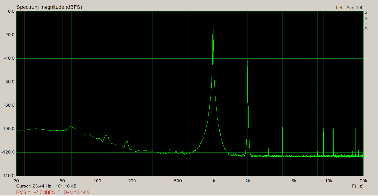
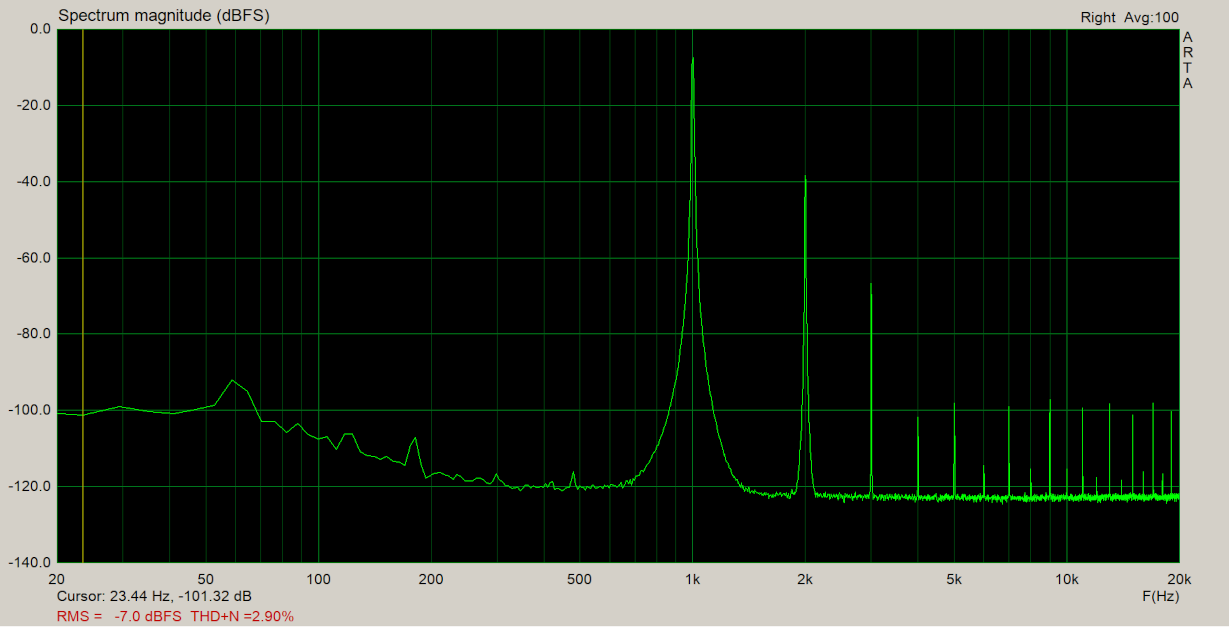
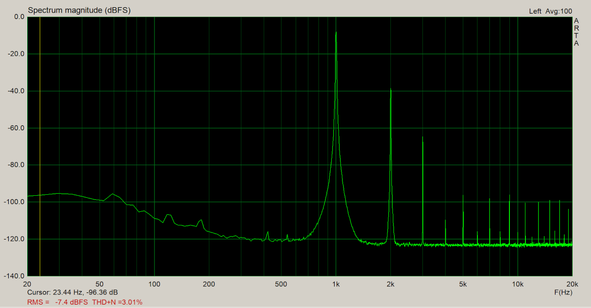
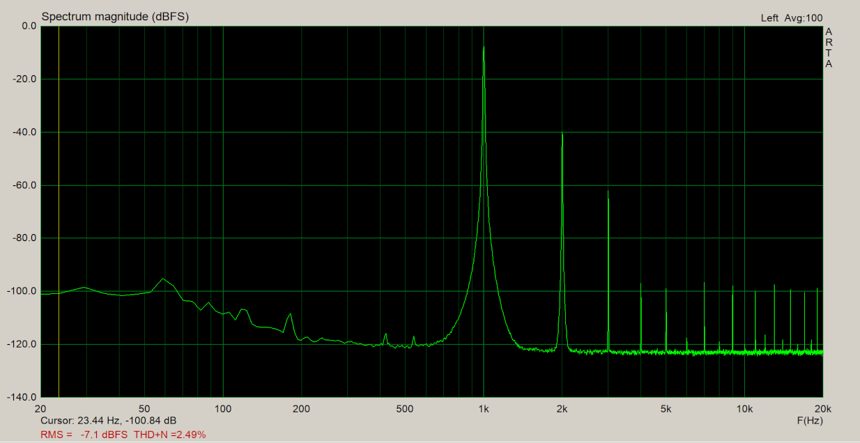
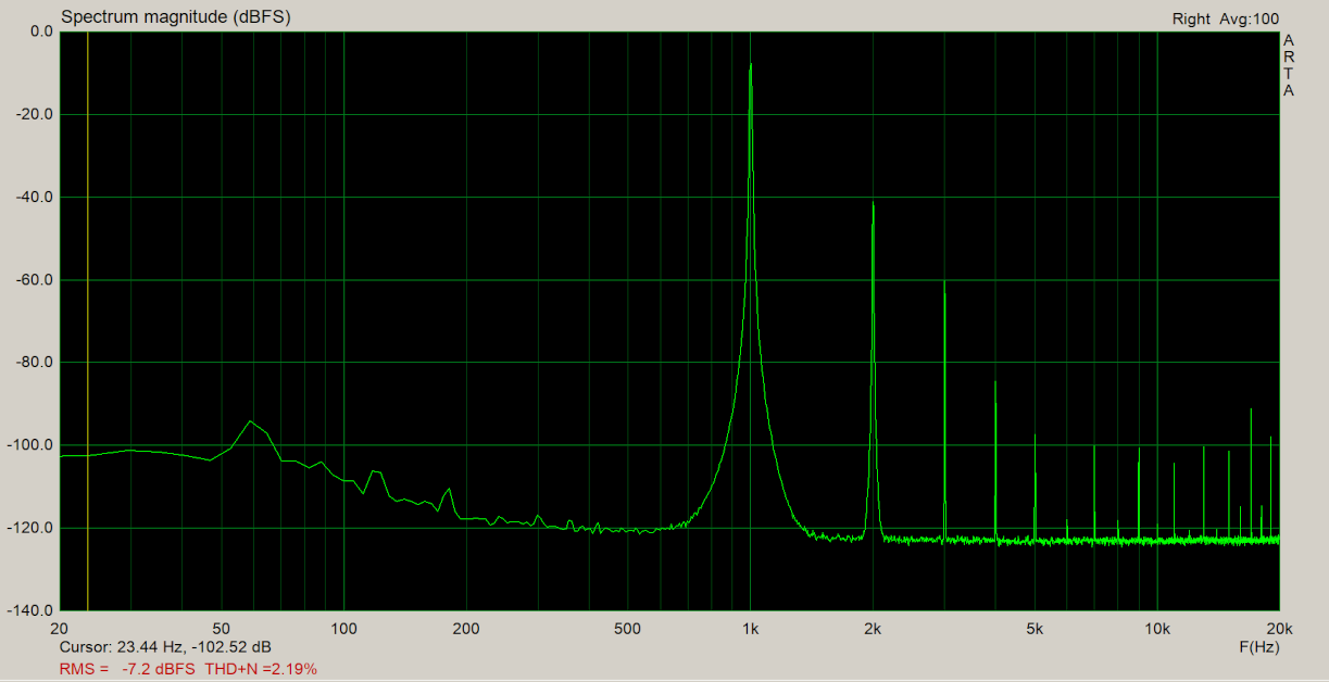
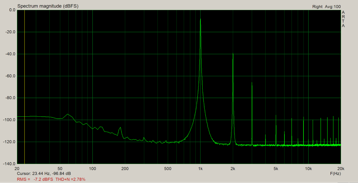
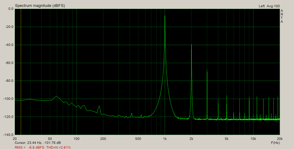
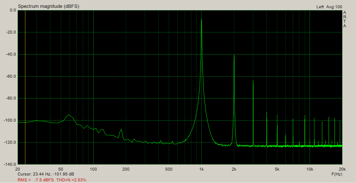
Gains - 13/12 13/13 distortion spectrum in pics
-
Yes pre-tinned copper is a good choice and many in the repair field use that. And smart running extra thick wire except sometimes then inductance may rear it's ugly head. I have made the executive decision to put my monoblock amps on a rack directly next to my speaker and run tops maybe 16" of wire so I just use 14awg as the length is so short the resistance is only about .003 ohms per wire. I run balanced to them so noise is never an issue with small signals either. Even with LaScalas you can put our ear up to the drivers and it's you would think the amplifier isn't even on.
-
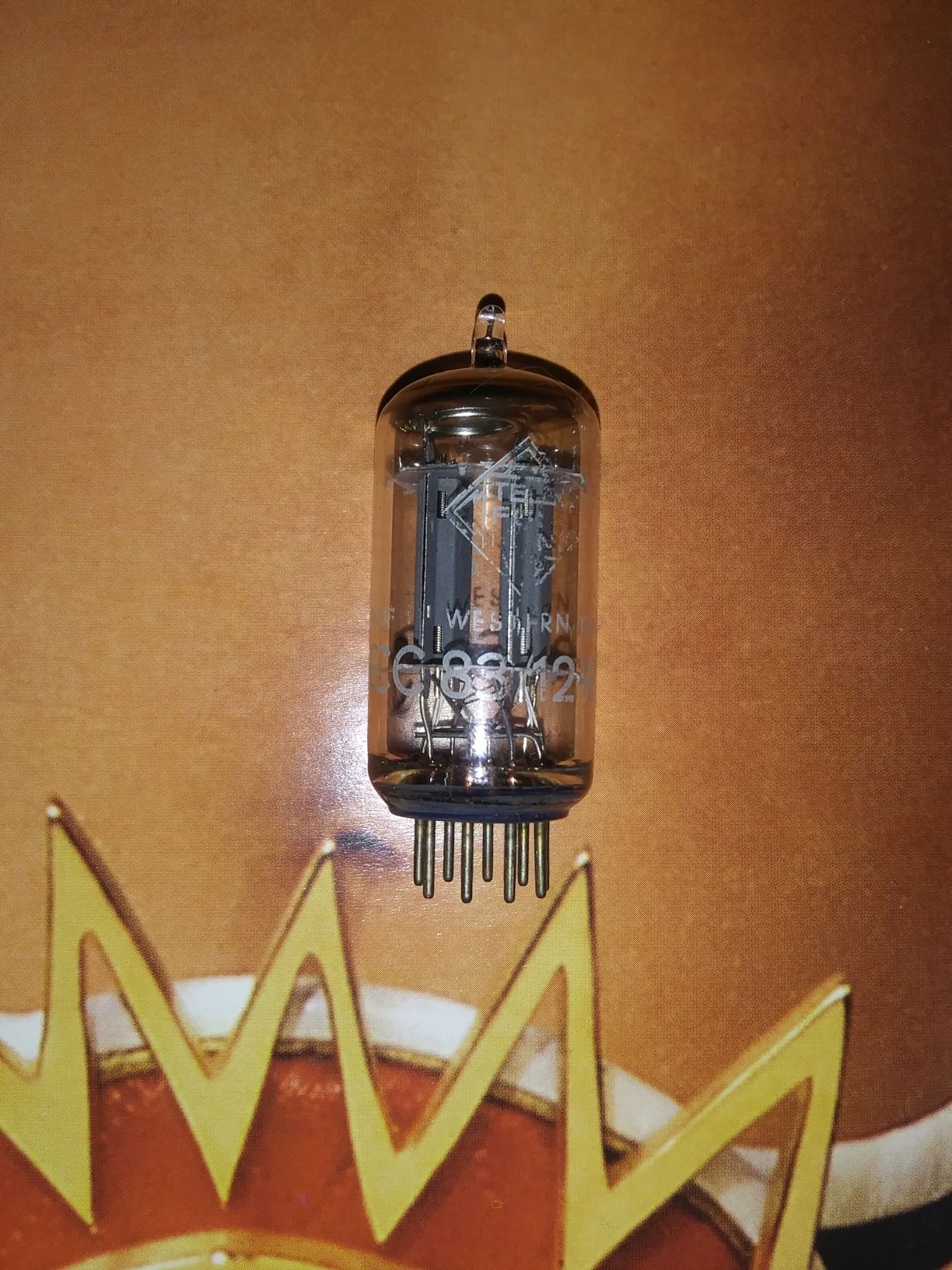
Telefunken ECC83/12AX7/7025 tubes
captainbeefheart replied to captainbeefheart's topic in Garage Sale
There are now only 4 left. Posts #14,16,17, and 18 are the ones left. I am not sure if anyone noticed but I accidentally posted the same section distortion spectrum image twice for tube in post #16 twice. I went back and updated it with the correct one, it was triode #2 that was posted twice so triode #1 was added which is 2.19% THD and triode #2 is 2.49% THD. -
ALL SOLD
-
Ok I see now what he was saying. As noted copper clad aluminum is fine and will work just as good as copper if you don't strip off the copper coating. Oxidized aluminum is extremely anti-corrosive which is good except that it isn't very conductive, or you can say it's highly resistive. Same is true for copper, once copper oxidizes it too will be a bad conductor from the resistive layer formed. That's why it's best to either terminate in a hermetically sealed connector or just tin it with solder then terminate.
-
Telefunken ECC83/12AX7/7025 tubes
captainbeefheart replied to captainbeefheart's topic in Garage Sale
Gain - 53/53 Distortion
-
Telefunken ECC83/12AX7/7025 tubes
captainbeefheart replied to captainbeefheart's topic in Garage Sale
Gain - 53/53 Distortion
-
Telefunken ECC83/12AX7/7025 tubes
captainbeefheart replied to captainbeefheart's topic in Garage Sale
Gain - 53/53 Distortion
-
Telefunken ECC83/12AX7/7025 tubes
captainbeefheart replied to captainbeefheart's topic in Garage Sale
Gain - 53/53 Distortion
-
Telefunken ECC83/12AX7/7025 tubes
captainbeefheart replied to captainbeefheart's topic in Garage Sale
Gain - 53/53 Distortion