captainbeefheart
-
Posts
1422 -
Joined
-
Last visited
Content Type
Forums
Events
Gallery
Everything posted by captainbeefheart
-
Yes they never comment especially publicly not to alienate any of their potential customers, especially ones with deep pockets. Knowing I am an electrical engineer I think he wanted to save some face by saying what he said in a personal email. They send a power cable MORE than sufficient for the current draw of their devices which is the only thing to worry about, loss across the conductor which turns to heat, general rule of thumb for house wiring I believe was no more than 3% but that may have changed. For devices I am certain they keep it well under 1% which is much less of a voltage change vs the normal line fluctuations. You mentioned filtering. IF a cable comes with some sort of filtering devices then it isn't the conductor doing anything to help, it is the filters which would be misleading saying "power cables make a difference" because well it really isn't the power cable doing anything it is the filters. Funny thing is people believe that the AC side filters are for the performance of the device but it isn't, the filtering that is important is AFTER the rectifiers because the rectifiers being highly non-linear loads will add distortion and ripple that needs to be filtered. We also filter for 120Hz noise being double the mains frequency from full wave rectifiers so they have a low impedance at 120Hz meaning any high frequency noise it will be a magnitude even lower impedance so rf gets filtered out. The REAL reason manufacturers place filters on the AC side of the power supply is to comply with FCC requirements to not pollute noise back into the power grid. This is why you see it mainly on computers, TV's etc..... that have switch mode power supplies which will highly pollute the grid if there weren't filters on the mains side. These usually comprise of Common mode chokes for common mode noise, Y caps across from each leg to ground for common mode noise, and X capacitors across the two legs for normal mode noise. Some also have normal mode chokes to further reduce normal mode noise. If you really want to isolate your gear as much as possible from your house power then run a dedicated branch circuit for your gear, this cuts down on noise from other loads being on the same branch circuit propagating noise across inductance of the neutral leg. IF you live in an area where you power has lots of noise on it, usually this is if your house is the very first house on the branch from the pole transformer, many think if you are the last house, not true. The first house has everyone else after you propagating noise across the inductance of the line, you being closest to the transformer will see the most noise, so the house at the end of the line will make the most noise which is shown most on your house first in the line. IF this is you then you may want a dedicated filter device connected to the dedicated branch to power your sensitive gear. The power "conditioner" will have all the common mode and normal mode passive filters I mentioned. The absolute BEST way of filtering noise and sometimes more importantly distortion is to have ACTIVE power conditioners, these have been around in the industry for medical/Lab equipment that needs as clean a power as possible. They are also used in industries for power correction to keep losses and costs down. The active filtering and power correction is amazing compared to just passive filtering. I feel passive filtering is just fine for most our needs but if you the person that needs to have the best look into active power filters, they are expensive but are amazing at what they do.
-
Too bad you already cut the holes for the Octal preamp tubes. A nice driver with lots of rolling options is the 2C51. That way you can roll 2C51, 5670, Western Electric 396a, or even the 6N3P. Bonus is all of these are not too expensive except for maybe the Western Electric 396a tubes. Another neat thing with these types of tubes is the pinout allows for a really nice mirror layout around the socket, the P2P ends up looking really neat and clean that way but it's easy because of the pinout.
-
I talked to Tom at Schiit about this, here is what he had to say.

-
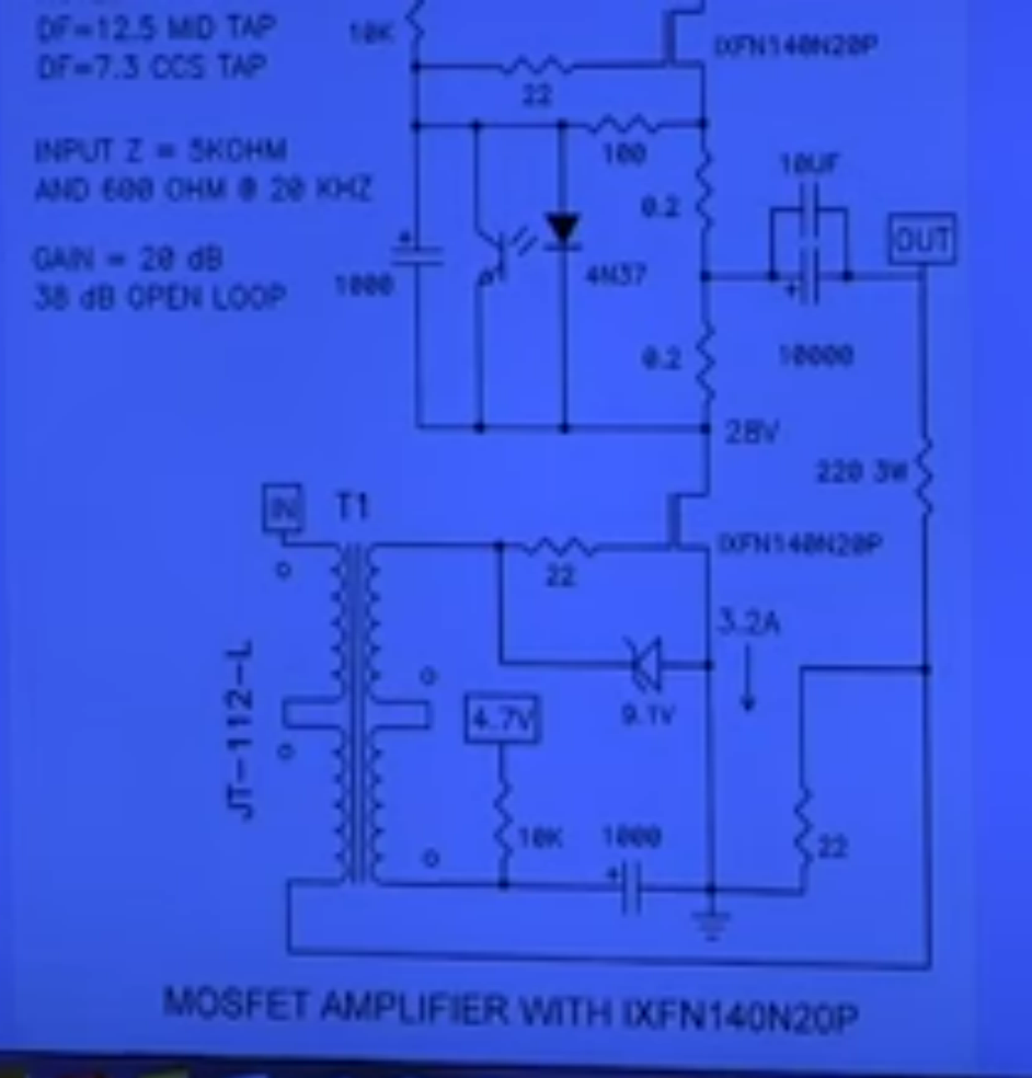
Think about this for a minute. The two Vfet amps you have take the output from the source ala follower output stage like most SS output stages. With a 300b amp that's not the case, they are not going to be follower output stages, to get the full 300b sound you need to take the output from the plate, hence the load in the plate circuit. That is exactly why I got excited when Nelson showed that cheaters version with standard Mosfets with the load on the drain this time unlike the Vfet amps with the load on the source, just like a real 300b tube amp taking the output from the plate. I highly suggest you try version with the load on the drain as it will be the most "tube" like sound. There are other amps Nelson has made with the output taken from the collector/drain, some have light bulbs as drain loads instead of a CCS that I have built that sound great but the output is more pentode like than triode like which is why the circuit I showed is so unique and about as close as you will ever get to a SET sound with SS components.
-
Here is the cheating version for those of us that do not have any of the actual Vfets. Same 60v rail as with the SE Vfet amp Sorry for the rough image. I used this image from BAF which is a picture taken of the lecturers screen.
-
Thanks! I somehow missed this version of the Vfet amps. When you mentioned he put out a single ended version I was hoping he was driving the load with the drain not the source, follower stages will not have nearly the magic. The version I built was the CCS was loading the drain not the source, and so output was taken from the drain not the source like the Vfet part 2 amp. It sounds like a ballsy bored and stroked 300b on ntiro. I will try and find the schematic for you if you don't have it.
-
I also cannot hear the difference between a low noise voltage source vs current source, as long as they are both well designed the sound will be good. By far the majority of DHT tube failures I have seen were the filament going open. I find the most from AC powered filaments honestly. Most linear voltage source supplies will have enough impedance from the filter stages to somewhat limit the in-rush surge current from a cold filament. Big improvements all around vs AC powered filament supplies. The current source supply limits current the most and is the least stressful to the filament of all three. Some tubes are so rare and or expensive I try my best to let them have a long happy life. 6SL7GT is a great tube. They are high mu so I doubt you are cascading the two triodes for each channel, let me guess, "SRPP" driver stage? At first I saw the octal socket and though you may be doing the classic JC Morisson type 6SN7 cascading stages to drive the 300b which is very popular. I currently have been wanting to get another 300b amp but really do not need any more amplifiers at the moment. You aren't helping building a 300b amp
-
Awesome!! I highly recommend a current source for the filaments instead of a voltage source, the 300b tubes will last so much longer this way. Rod Coleman makes nice boards if you don't have a board for this. What are you driving the 300b with? Class A1 I presume?
-
Glad to see someone else enjoying the quality of the Tektronix scopes to this day. I have nice digital scopes also but for some reason I use the 475 the most on the work bench. no worries
-
When I start testing for the breakpoints there are no compensation caps in. The cap you are changing is the lead network as it causes it to break upward and lead which is usually set at the second breakpoint (-90°) after you set the lag compensation. The lag compensation breaks downward and is most likely C10 and C17 in your schematic (100pF at plate of input pentode). This frequency is chosen by the very first breakpoint, -135° when testing with no compensation. Most people only mention or fiddle with the lead compensation cap in parallel with the feedback resistor but the lag network is just as important if not more so.
-
You must be on DIYAUDIO(dot)COM because I made a Honey Badger also. I sold it when I started building the SlewMaster amps. I still have several extra unpopulated boards for the Slewmaster if you are ever interested in building one let me know. Question, you said you built Nelson's SIT amp but I thought they were push pull but you are saying it's SE? Do you have a link for the SIT amp you built that is SE?
-
R-110SW / R-112SW / R-115SW Repair Blog
captainbeefheart replied to ngen33r's topic in Technical/Restorations
Just scrape off the thin top insulation material on that trace until you see shiny copper, a razor works well. Clean and tin the trace, the pad side that has lifted off try and leave it where it is. Now clip off some 1/2 watt resistor leads and shape one end into a circle the same size as the pad where the cap lead goes through and have the resistor lead long enough to lay onto the newly tinned trace. Next solder it all together and you now have a repaired trace. I have had to do this so many times because of people trying to do repairs themselves with poor soldering skills. Removing components from boards is much harder than installing them so usually when noobs try and remove parts they use way too much heat and don't have the proper methods or tools so pads get lifted off when removing components. I almost never have to run wires because often the trace goes to several places so you have to run several wires, I find it easier and best just to repair the bad pad and solder to the trace further down under the insulation. -
The blinking light is fault indicator which is why you have no sound, it is in a protection mode. These active speakers use the same technology as the subwoofers that suffer the same problems. You need to either bring it to a tech if they are out of warranty or open it up and post pictures, you may get lucky with seeing something burnt or some swollen blown caps or something but usually that isn't the case and you need to know how to properly test each stage of the switching supply as I doubt it's the amplification board. Simple way to see if it is the power supply is to measure the voltage out of the power supply board to the other boards.
-
I think I just found a new friend!!! I even have the same Tektronix 475 analog scope LTSpice is a powerful tool in the arsenal for amp builders but many home brew builders choose not to learn how to use it. I tend to use it more for my own designs that way I can tweak stages for optimal performance etc.. A long time ago I did make a folder of vintage amps that I built in LTSpice, I think I still have the folder somewhere in my backup hard drive. You listed stability and compensation but I have found that the real world amp will be much different with layout parasitic variables (mainly stray capacitance at the plates of gain stages) and getting a precise output transformer model in LTSpice isn't easy either so I wait until the amp has been built to do my feedback compensation networks. I use my scope in X-Y mode with the input and output signals and use Lissajou graph to find the amplifiers breakpoints. Basically a 45° angle has a very specific pattern on the scope in the form of an elongated circle, I sweep the frequency until the exact elongated circle dimension is reached and then write down the frequency. This will be the phase shift difference between input and output in 45° increments which I then use to make a bode plot. The bode plot is needed to calculate the lead/lag compensation network values. Once they are determined I install them into the amp and re-test with square wave testing. I have found this to be the quickest and most accurate way to do this. Sometimes if it doesn't give the results wanted you may have to tweak the values up or down a little to see if they improve but if you take the time to do the breakpoints accurately it should be good to go the first time around.
-
Many times on many different systems. I have even gone further than that to also take all sorts of measurements to compile as much data as possible like cable electrical properties, drop across the cable, temperature of the cable, and all the typical measurements at the output of an amplifier. I have a Shunyata Venom right here that does look great, has a solid connection and it was gifted to me for helping a fellow audiophile. He wanted me to "try it in my systems", I didn't want to be rude and of course took it and did my normal comparison vs my "stock" cable to no avail of any improvements except for visual. This isn't the first time someone has gifted me a fancy cable. I haven't kept one so I probably won't keep this one, if I can sell it at a reasonable price to someone else that will get enjoyment out of it that is great as long someone is making good use of it and cherishes it more than I would. Some of my friends still believe in them so they let me borrow them to test and "audition". It fascinates me honestly, it's not like I haven't tried to hear or measure a difference. I would love some actual data to corroborate the phenomenon but no such luck. Looking for a Shunyata Venom power cable slightly used? 😜
-
There is only really one "improvement" that can possibly account for you possibly hearing any sort of difference and that is if you had a ground loop with the standard 3-prong grounded cable and switched to a cable that did not have the dedicated safety ground which removed the ground loop. Or, because during the day your power from the mains can change and for whatever reason the gear you have is sensitive to power line issues and you are hearing that as a coincidence. The latter is a complete stretch but I will not rule it out. Other than that there is absolutely no way a power cable can make any sound difference. If you don't listen to me listen to the company that engineered and built your amplifier (Schiit), I assume they kinda know a thing or two about these things also no? It's great you enjoy them and that's all that matters. There are so many people researching these sorts of things that end up reading these threads while searching for information and it can't hurt to get opinions on the matter for both sides of the topic. I respect your opinion as it is totally valid to only report what you think is happening and what you are hearing and feeling on the topic.
-
From the horses mouth.
-
For the TU-8200 I was only saying I like the design of the circuit, much better than many much more expensive amplifiers. I wasn't suggesting to change anything, especially since it is all on a PCB it would be difficult to make the change. I was more or less thinking out loud that I would be over the moon for the amplifier if it ran Class A2 grid current mode. With low powered amplifiers even if you are listening at around 1 watt of power average, dynamic music needs headroom for the dynamic range and the transients or peaks in the music. General rule of thumb is 20db headroom from average listening powers. Example average listening is 86db, that means you need headroom of 106db, with 94db like the Heresy that would equate to power of 16 watts of power. That amp in A2 operation would get you closer to the 16 watts power you need but more importantly if you run the amp closer to full power it will not go into grid clamping which causes a gross bias shift and blocking distortion, this takes the amp time to shift back into normal operation. With A2 operation none of that happens. I know tube rollers love the active auto bias so from a design perspective they most likely figured that would be a huge selling feature for customers to be able to change their own power tubes without worrying about having to re-bias. I would trade the auto-bias for A2 operation as it greatly enhances performance where the auto active bias does not, it is more of a convenience technology. One issue with the active auto-bias which has become very popular lately as a selling feature in tube amps they fail very frequently. When I purchase or build an amplifier I expect it to be bulletproof and last a long time before any need for repairs but I have been seeing a lot of these active auto-bias circuits fail prematurely. Nothing to stress about, I really think they did a great job with the amplifier design and I am only nit-picking at this point and like I said if it was A2 operation I would have the credit card out ready to purchase one!! Sorry I messed up and meant to ask about the amp on the Heresy, the Heresy is a better speaker compared to the KG4 IMHO. Triode mode should be the best of all the modes and personally I would be listening to it like that the vast majority of time. As for Pentode vs Ultra-Linear I am not a fan of Ultra-Linear, it is grossly overrated because it tests well on a resistive load but under reactive loads it doesn't do so well. I have found that a different form of local feedback (instead of sending plate signal to the screen grid like ultra-Linear, signal from plate goes to the control grid) nested inside global feedback sounds a lot better in real world with speakers. Unfortunately the TU-8200 does not have the plate to grid local feedback in Pentode mode so that mode will not be at it's full potential but give it shot I am very curious what you think of Pentode mode vs Ultra-Linear mode. Another great engineering practice they followed was putting an RC Zobel network at the output to keep loading from reactive speaker loads from rising with frequency, it keeps it flatter for better performance and lower distortion at high frequencies. You would be surprised the vast majority of modern and vintage tube amplifiers do not add this inexpensive but very crucial addition. Since the TU-8200 has the Zobel networks it should be much smoother in Pentode mode than if it didn't. My hats off to Elekit!!
-
You do not have to find a static induction transistor to get the same type of triode curves, all that is needed is some drain to gate feedback. Nelson showed a schematic with this arrangement during one of the BAF lectures where he described the circuit and how it gets the same results as the SIT Sony V-fets. Basically it is an old tube trick instead of completely triode strapping a pentode and getting much less power the "Schade" type plate to grid feedback gives power like a pentode but distortion and curves like a triode. I prefer this arrangement over the overrated ultra linear type feedback output stages. With the Mosfet drain to gate feedback, Nelson explained using just a resistor drops the input impedance of the Mosfet so low that you basically need another power amp just to drive it so he added an input transformer and bootstraps it to the output to process the feedback and instead of lowering the input impedance it increases it making it easy to drive with any source or preamp. Single ended Class A, current source loaded with bias around 3 amps you get 20 watts output @ 1% THD. It can get to 50 watts before clipping but the distortion is high so it is conservatively rated at 20 watts. I loved the idea so much I made one and let me tell you amazing with Klipsch speakers. I have been toying around with adding some positive current feedback like the F7 to get the damping factor to >100 but haven't tried it yet. It controls the La Scala's just nice but some of my other speakers could use some more damping it seems so I will get around to trying to improve upon Nelson's fantastic design that nobody seems to know much about and not many have built it. I highly recommend making one or having a builder make you one they are just the Bees Knees.
-
I really like those amplifiers especially for the money. One thing is I would trade the active auto-bias feature for either a interstage transformer or a follower circuit to drive the output stage into grid current as it drastically improves performance and you get more power out as a bonus. With the KG4's do which mode do you find yourself listening to, triode, UL, or Pentode?
-
Well designed devices will mute the outputs until things have stabilized. If no muting function and say you turn on the power amp before the preamp you can certainly hear some noises as the preamp warms up. Noises like slight hum and thermal expansion of metal creaking popping as tubes heat up but the way he described the noise was "nasty feedback" which brings to my mind a squealing noise. The squealing noise is instability from positive feedback, this is a sure sign the amp is marginally stable at best during normal operation but during power up/down the instability can become so bad you have squealing from it oscillating. That is why it squeals, it is an oscillation that shouldn't be there. Unless the OP wants to change his description I stand by my statements. Any squealing even during power up/down is a sign of oscillation and that even though the amp doesn't do it during normal operation for it to do it during a power cycle means that the amp is marginally stable at best. Dismiss these warning signs at your own peril, even if you had it serviced recently doesn't mean anything. I have seen multiple vintage equipment come to me for issues just like this, last one that did exactly what you describe had different style coupling capacitors installed. The preamp had feedback around the tone circuits where the capacitors were replaced and during power up/down the amp went into oscillation which it never did before and shouldn't do. The type of capacitors allowed for a slight parasitic coupling between components which decreased the phase margin and hence lowered stability. During normal operation the squeal went away but on the scope you could see an oscillation around 35kHz that changed with volume changes. Took a bit to find the issue but once the capacitors were swapped out to small film types the phase margin increased and the preamp was stable once again. Basically the squealing is from the oscillation dropping low enough in frequency to be heard by the human ear, during normal operation the oscillation frequency increased high enough to not be heard by the human ear.
-
Of course we can but it can be very technical so not easy to explain. For distortion alone the THD% doesn't tell the complete story which is why we look at spectrum analyzers. It can also be related to music theory in terms of harmony, hence harmonic distortion. Second harmonic is an interval of one octave, which is the same exact note just up one octave so it is very harmonious and reinforces the fundamental. This type of distortion from non-linear functions is the most benign. Third harmonic is an octave above a musical fifth interval, so a 12th. The fifth interval is a very powerful one, in guitar lingo a power chord is almost always just the fundamental and the fifth while omitting the musical third interval. The fifth is harmonious to the fundamental but in a more aggressive manner which is why power chords on guitar with some distortion effects sound so big and powerful. When you start getting higher than the 4th harmonic the intervals become dissonant not harmonious, they sound "off". The flat fifth in musical terms is called the blue note, it was actually illegal by the church to play this interval as it was so dissonant it was called the devils music. Play a diminished chord on any instrument and you will hear how "off" it sounds. These higher harmonics are for the most part not wanted in hifi as they become fatiguing and dissonant. So a tube with low distortion, predominantly second harmonic will sound smoother vs one with high odd harmonics, which can be harsh, dark etc...Linear loads create odd harmonics, so push pull amps will have more odd harmonics vs a single ended amp which is dominated by second harmonic. So although the single ended amp has more THD%, it is benign due to the majority of it being second harmonic and very harmonious. I will not get into pentodes and loading which creates higher distortion rising with frequency or interelectrode capacitances etc... There are many variables but distortion spectrum is the biggie.
-
Yes. Even within the same production batch of the assembly line there is a tolerance which is why the datasheet gives "average characteristics". I was measuring my Telefunken 12AX7's the other day, I have about 20 of them left and in the same test circuit measured at the same output level and frequency they were anywhere between 2% THD to 5% THD. And to complicate matters the ones that tested at higher THD% didn't show the same FFT spectrum on my distortion analyzer. Two tubes with 3.5% THD where one is almost all second harmonic will sound different than the other that has more third and higher harmonics. I tend to focus on tube brand and production years for longevity and consistency, that's it. After that I just test them in circuit to find the best for the application. For example the ones I tested at 2% THD and were mainly just second harmonic go into my phono preamp for best results. The ones testing higher are fine as phase inverters, followers even guitar amp duty.
-
Yes I did say that but you are twisting it into something it isn't from your misunderstanding of the functions. How can an amp or source change the distortion characteristics of a loudspeaker? They can't. If the woofer is at 10% THD at say 95db for 50Hz then that is it's own properties and nothing before it can alter it. Is that clearer for you?
-
You are only hearing what you want to hear. Read my other response but I will repeat it again for you. Speaker performance cannot change, they have their own characteristics that are already set that you cannot change. If you input a perfect signal into the loudspeaker and at a specific output and frequency you get say 30% THD, that distortion will always be there no matter what amplifier or source you choose. Get it? AFTER you have chosen a quality loudspeaker then you can improve on the rest of the chain but their differences are improvements upon themselves and sum with the loudspeaker, it's just the loudspeaker imperfections and distortions are of a magnitude greater than all the other electronics in the chain so they are much smaller differences compared to changing loudspeakers. Make sense now?