dBspl
-
Posts
146 -
Joined
-
Last visited
1 Follower
dBspl's Achievements
Forum Veteran (4/9)
84
Reputation
-
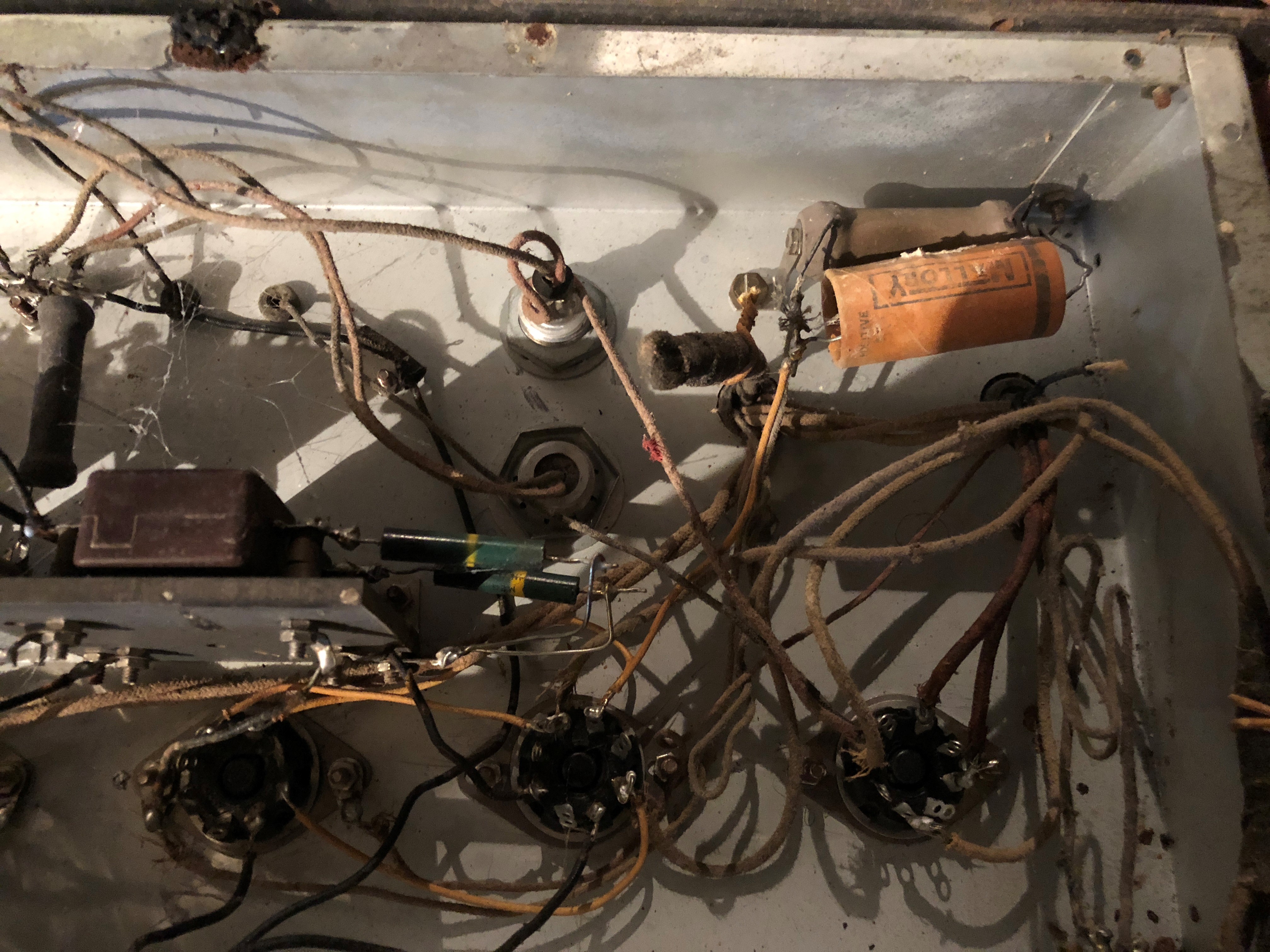
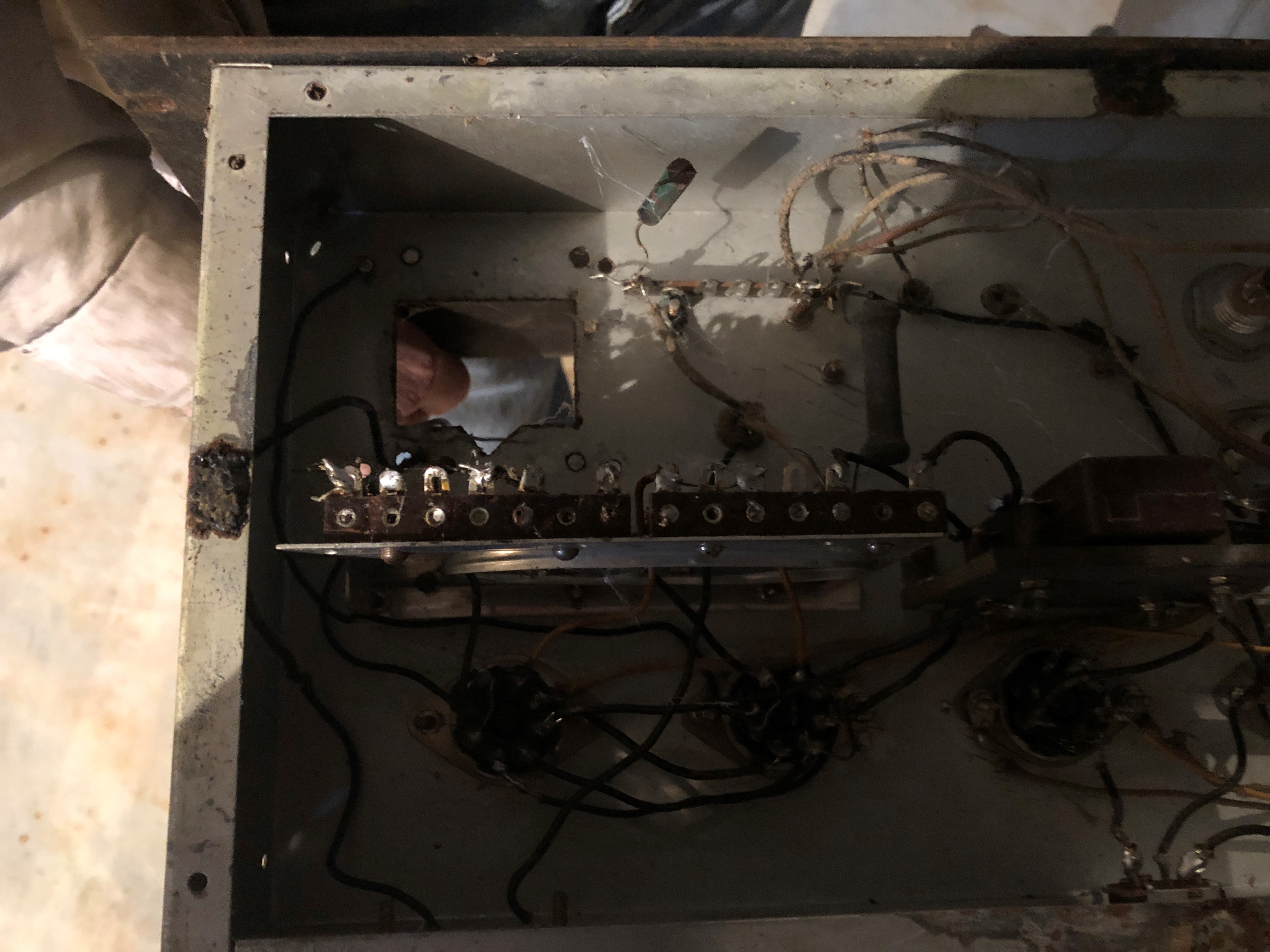
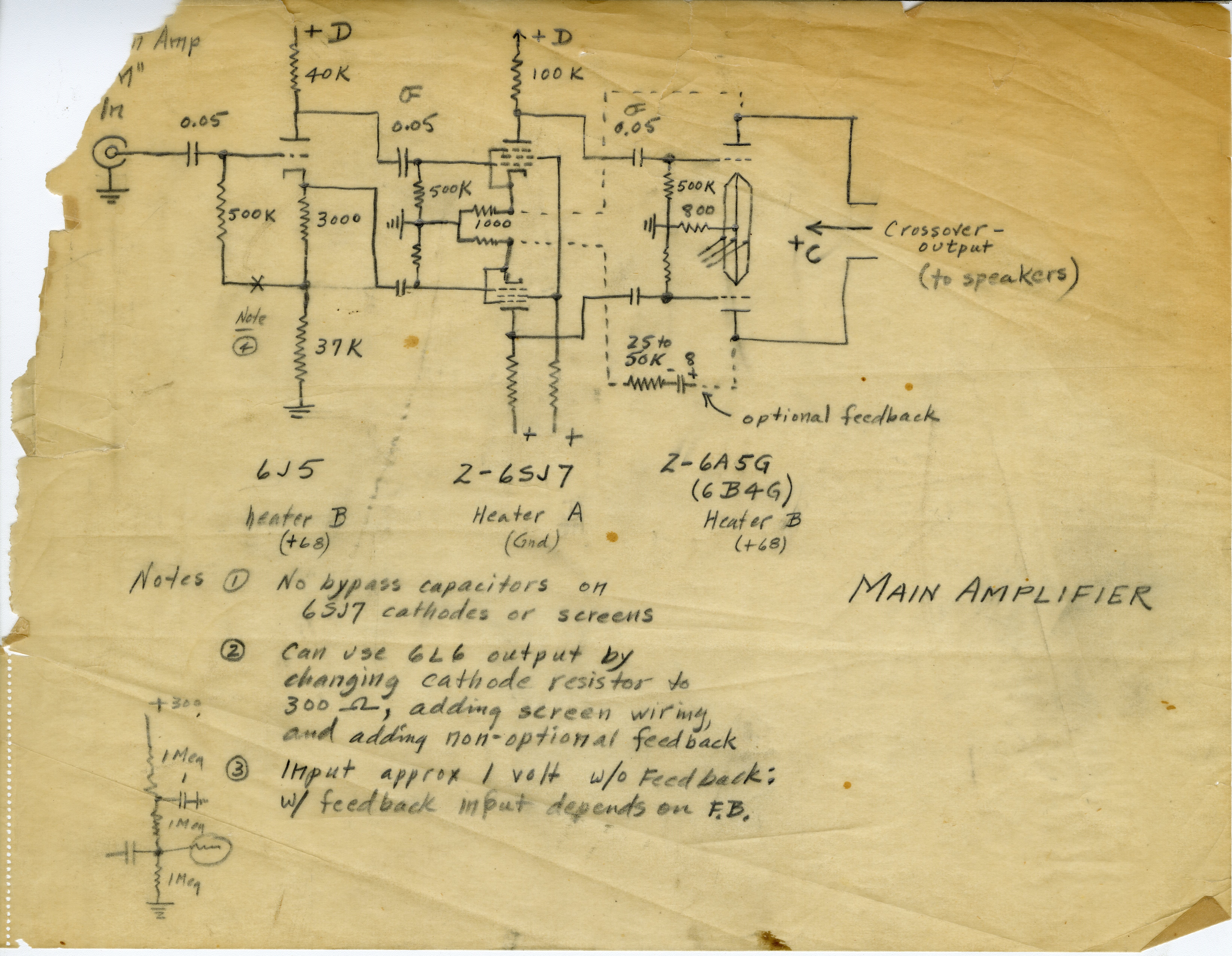
I attached the only pictures I took of the underside. It's not very pretty. The #3 photo is the power supply and output tube side of the chassis. The #4 photo is the pre-amp and driver side of the amp, although this side also includes the (missing) output transformer. There is an discrepancy that I need to figure out. Jim confirmed the metal tubes are 6SJ7's as shown in the schematic (driver tubes), but the there is no 6J5. This is odd given the 6J5 in the schematic serves as the phase splitter. I'm guessing the front-end of the amplifier has a different topology than the schematic. It could be an earlier version? I believe the rectifier is a standard 5U4G. The 6A5G is rated for 10 watts in class AB. A 10 or 15 watt output transformer with a 5000 ohm primary would probably be correct. dBspl

-
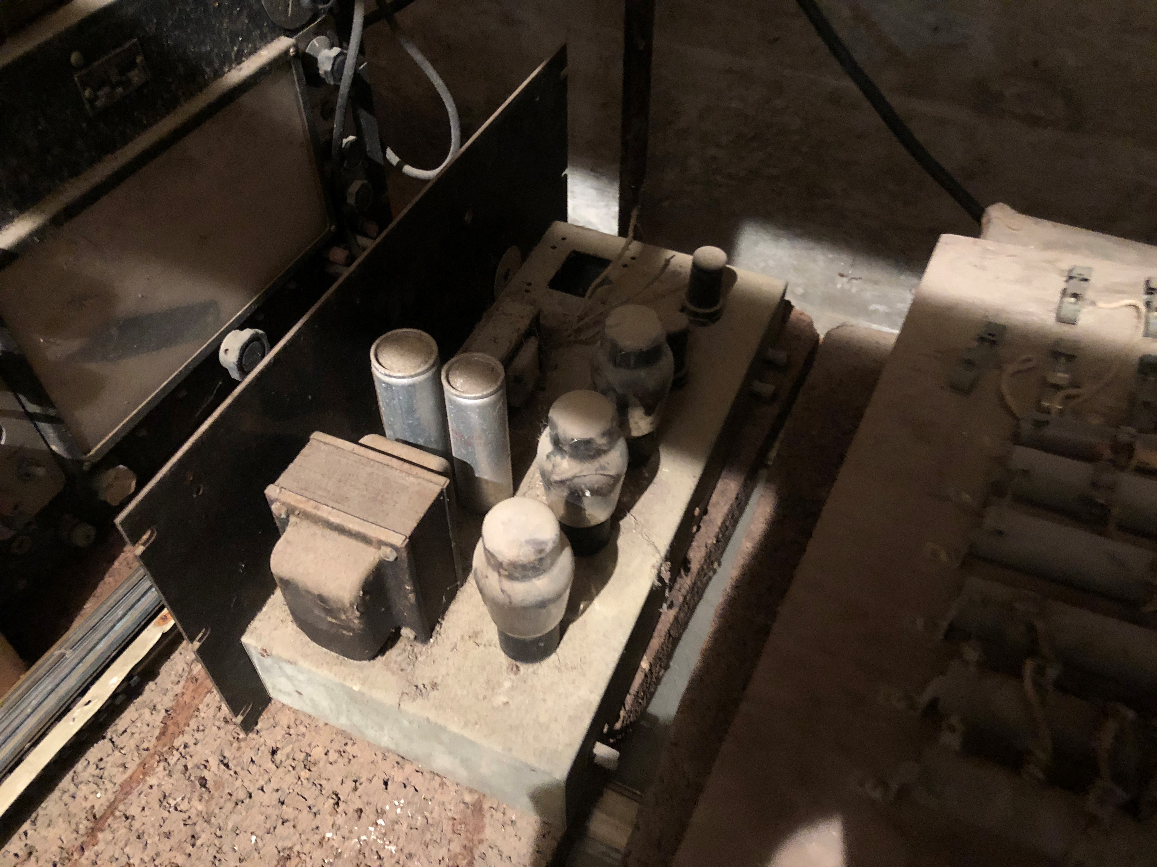
So I was down in Hope earlier this week and Jim Hunter was showing me a few things in the museum. We were down in the museum basement and I was just looking through some of the items in storage and noticed a piece of tube gear stuck in back of one the storage racks. We pulled it out for a better look, and it turns out that it is the PWK 6A5G amplifier based on the schematic shown above. It looks to be in pretty good shape. It is missing the output transformer and the rectifier tube has separated from its base. As you can see, the chassis is designed to be mounted in an equipment rack (typical PWK). I'm guessing, but this is probably his laboratory measurement (and probably listening) amplifier from the late 1940's to early 1950"s. dBspl
-
I heard PWK remark several times that he couldn't hear above 5kHz. Of course, he was in his 80' and 90's at the time. He would say it was due to "shooting too many 45"s without hearing protection". But he was an experienced listener. I recall one time Hunter had purchased a vintage (& working) RCA theater speaker and amplifier for the museum. Before the speaker and electronics were moved to the museum he wanted to get an anechoic chamber measurement. We had positioned the speaker on the chamber door and decided to listen to it first. The loudspeaker when positioned on the door actually faces into the main part of the lab, so it actually makes it possible to perform a listening test from this perspective. Then you simply swing the chamber door to position the speaker inside the chamber to take your measurements. Anyway, PWK walks into the lab about this time, and as usual, takes an interest in what we are doing. He listens to the speaker along side us...and then walks over and grabs a piece of plotting paper (this was in the days when frequency response measurements were still made using X-Y plotters). He takes out a pencil and draws the frequency response of the loudspeaker we were listening to (and hadn't been measured yet). After a few more minutes of listening we placed that piece of plotting paper on the plotter and take the measurement. PWK's hand drawn curve was exactly right. I was a young guy then and I remember wondering how he had done that. Although I probably haven't seen that curve in almost 30 years, I'm sure that piece of plotting paper is still in the archive somewhere. dbspl
-
Sensitivity loss with compression drivers
dBspl replied to jazzmessengers's topic in Technical/Restorations
I'm simply using a voltage reference to state sensitivity. Since an amplifier is a constant voltage source, you can "de-sensitize" the driver/horn combination however you wish. Your point is that the power response doesn't change, which is true, but I also mentioned that in the second paragraph of my original post. Kerry -
Sensitivity loss with compression drivers
dBspl replied to jazzmessengers's topic in Technical/Restorations
It seems like we're making this out to be more complicated than it is. For a given compression driver, the on-axis sensitivity of a constant directivity horn will be less at higher frequencies than a similar horn with a collapsing coverage pattern. This difference in sensitivity is inherent in the driver/horn design. If the target magnitude response is the same in both cases, then that difference has to be made up somewhere - regardless how you go about it. As a result, you should always be able to measure that difference at the driver terminals. The constant directivity horn will always require more power at high frequencies to achieve the same on-axis SPL. Kerry -
Sensitivity loss with compression drivers
dBspl replied to jazzmessengers's topic in Technical/Restorations
My guess at what they're getting at is that for a given compression driver, a constant directivity horn will typically be less sensitive (on-axis) at high frequencies than a horn with a collapsing coverage pattern. The difference in sensitivity will follow the difference in Directivity Index between the two horns. Since equalization is typically referenced to the least sensitive part of the horns useable passband - it follows that the constant directivity horn will be equalized to an overall lower sensitivity. If the equalization is done properly - the efficiency of the system in both cases should be retained. And if the horns are of similar size, the power response in both systems should be very similar, too. My point here is that you're simply sacrificing sensitivity for a wider coverage pattern at high frequencies. However, nothing else has really changed. Kerry -
Seti, You might get there before I do. I have another project that I committed too before I saw this one. I'm not very familiar with tube circuits, but it hit me as odd the phase inverter circuit is also the front end of the amplifier. DrWho, I understand what you're saying. I suspect it would also be a challenge for me to get up to speed on the software, but I may take a look at it. I did find a couple of 6J5 and 6SJ7 tubes (metal envelope) in a box of old tubes I have. They tested good, too. Thanks, Kerry
-
It probably wouldn't hurt to go through it and check for a cold solder joints, too. Kerry
-
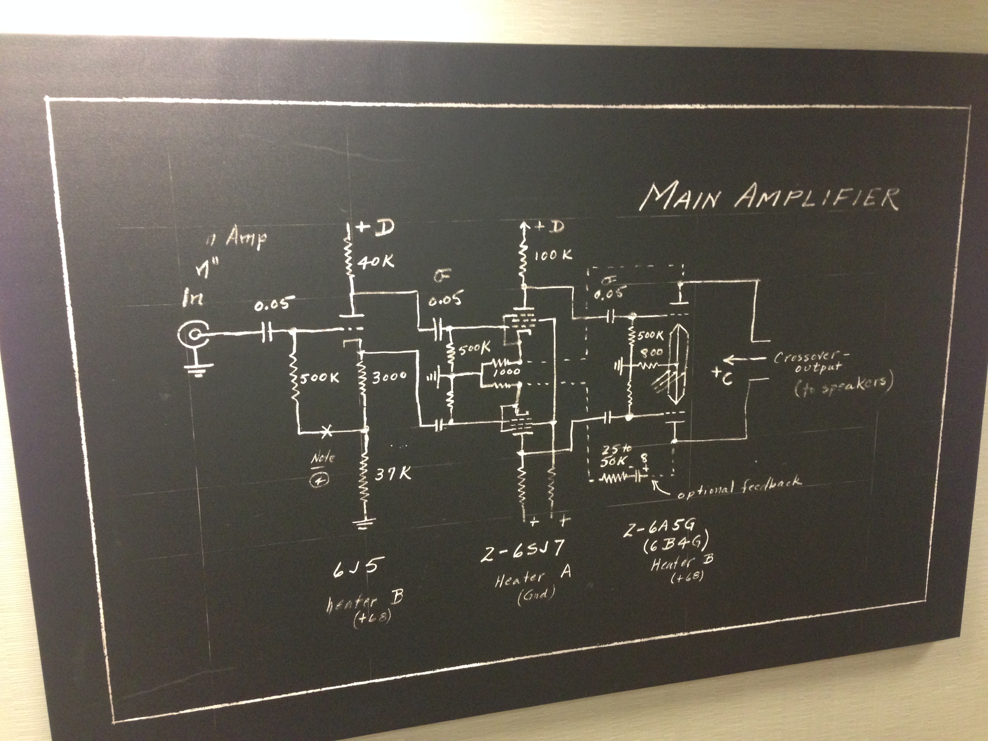
I thought you guys might enjoy this... I've probably passed by this picture in the engineering lab in Indy a 1,000 times. It finally dawned on me one day as I passed by it that it's an amplifier schematic drawn by PWK's own hand. Hunter was able to find the original drawing the picture was based, but unfortunately the drawing isn't complete. First, the power supply schematic is missing, and second, the amplifier schematic doesn't show an output transformer. There's also a puzzling comment about "crossover output (to speakers)", which doesn't make a lot of sense. Anyway, I was thinking it would be cool to build this amplifier given the connection to PWK. The 6A5G output tubes are very similar to the 2A3, and the output is in the range of 10 - 15 watts push-pull. I'm guessing the schematic was drawn in the early 50's, but going all the way back to the early 40's seems plausible, too. It's little surprising the schematic isn't dated since PWK rarely wrote anything down without putting a date on it. Maybe the date is with the part of the drawing with the power supply schematic. I'm planning to take a shot at designing a power supply, but I've never really done that before and I may need some help. The C+ & D+ voltage supply isn't specified, but based on the 6A5G data sheet, it looks like the C+ voltage should be around 325. The D+ supply looks like it needs 300 volts based on the 6J5 & 6SJ7 tubes. I'm not sure what the screen supply voltage on the 6SJ7 should be. It could be as much as 300 volts, but the little schematic shown on the lower left hand side of the drawing could be indicating the screen voltage should be 100 volts. I don't know. From what I can tell, the output transformer primary needs to be 3000 ohms? Kerry
-
If the problem is common to both channels, then it's likely the power supply since that's the only part of the circuit both channels appear to share..
-
I'm no expert, but I would start with the power supply to confirm all supply voltages are good. But it sounds like a leaky coupling capacitor in the output stage (charging & discharging). I've owned a PV3 since the mid-80's. It's a great little pre-amp. I still use mine regularly. Kerry
-
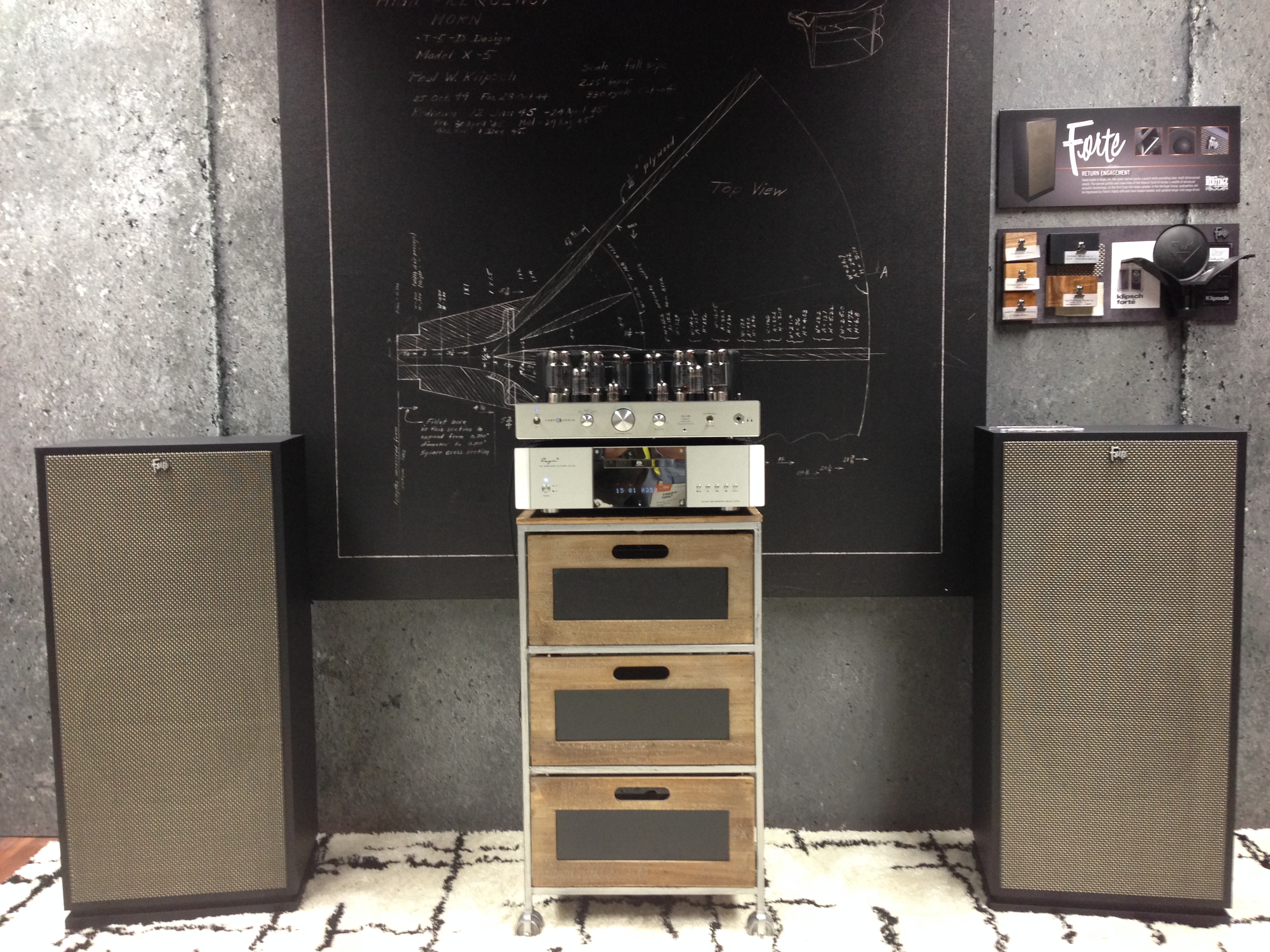
Here's the demo pair of Forte III's setup in the Klipsch booth. We've already had great feedback and the show hasn't even officially opened yet! I'll grab a better picture of the Forte III in California Black Walnut (also on display) and post it when I get a chance. Kerry
-
While what you say is true, it's probably not quite as bad as you might think. At 400Hz the output is the sum of the midrange and woofer horn together. The apparent size of both apertures will help control vertical coverage. And because the summation continues (to a lessor degree) above and below the crossover point, the vertical coverage will be narrower than the if the midrange were operating by itself. The woofer horn should have some measurable effect on up to 800 Hz, or so. Kerry
-
Yes, the Tascam was the unit used for the slide/demo they had in the front office. PWK had a Revox B77 at his house, which is probably the one you saw. I believe the other unit was a Tandberg. Kerry
-
From at least the mid 80's to the end of his life PWK used a Crown D75 to power the left/right Khorns and a BGW Model 100 to power a Belle center channel. I want to say he used a McIntosh C28 pre-amp at some point, but I don't recall seeing it by the mid-late 90's. I was probably the last person to go through the system and get it setup properly after he became too feeble to deal with it. I don't know what happened to that equipment after his death. He had a couple of really nice reel to reel machines, as well. There was a Marantz 8b in the museum, but I don't know its history. The model 7 pre-amp sat on a shelf in lab unit just a few years ago. I remember hooking it up once a long time ago just to see if it still worked - but it had issues. Kerry