

Arkytype
-
Posts
448 -
Joined
-
Last visited
Content Type
Forums
Events
Gallery
Everything posted by Arkytype
-
A time-aligned top end - Part II
Arkytype replied to Al Klappenberger's topic in Technical/Restorations
As I e-mailed Al, it takes me longer to get the Eliptrac set squarely on the turntable and to get the mic precisely aligned than it does to make the polar measurements! We have a 350 seat auditorium which I used to make all the Edgar and Eliptrac measurements. Both horns were "firing" into a large curtain on stage about 50 feet away.The gating of the ARTA measurement software ignores any reflections with a round trip that long anyway. More about ARTA later. The mic capsule used is a Bruel & Kjaer 4135 1/4" which is, as PWK was fond of saying, "Flatter than a bookkeeper's arse". I used corrected frequency response curves to offset what little non-linearity the mic has. The B & K mic preamp feeds a B & K 2610 Measuring Amplifier which is flat from 2-200k Hz. The absolute level calibration is done using a Bruel & Kjaer 4220 Pistonphone calibrated with the past 12 months. Its absolute accuracy is guaranteed at + or - 0.2 dB. The software interface is a Presonus FireBox which is a little picky about latency and sampling settings but eliminates the necessity of having to use a sound card. ARTA will work with many soundcards as well as outboard firewire interfaces. I've been using a licensed version of ARTA for a few months now and have found it almost intuitive to use. The manual for all three sections of ARTA is on line and mixes in theory and measurement in a well-written format. The software and manual author, Dr. Ivo Mateljan, is the head of the Electroacoustic Laboratory at the University of Croatia. http://www.fesb.hr/~mateljan/arta/index.htm You can download a free demo version of ARTA which allows full functionality except for loading and saving data files. The license key is around $125.00 and is well worth the investment if you are serious about acoustic measurement. Now, do you need to invest in laboratory-quality gear such as Bruel & Kjaer to measure your system? Probably not. Parts Express has a neat USB microphone with software from Liberty Audio (Praxis) for around $300.00 that looks like a real bargain. http://www.parts-express.com/pdf/390-790b.pdf Having measured just about anything that moves air, I've learned that it's easy enough to make a measurement. Interpreting what the wiggly lines mean, now that's a topic for another post. Lee -
Prolonged listening may result in excessive eargasms. Lee
-
Don, To quote Yogi Berra, It's like deja vu all over again! The RMS vs. continuous power topic came up in this forum in November of 2004. http://community.klipsch.com/forums/t/47910.aspx?PageIndex=1 Rather than re-write my brilliant contribution back then, here's a replay plus additional info to make your head swim: "There is no such quantity as "RMS power". You won't find it in any textbook or in the National Electrical Code. You will, however, find it in the sales brochures of most amplifier manufacturers. McIntosh Laboratories has used the correct power rating terminology of their amplifiers for many years. It is: "Continuous average sine wave power". While we should measure the voltage across the load with a true RMS voltmeter or the current through the load with a true RMS ammeter, that doesn't mean the resulting power quantity computed using Ohm's law is "RMS watts". Assuming the source is a sine wave, you are measuring the average power delivered by the amplifier. This is equivalent to the DC heating power delivered to a specified load resistor. I suspect the RMS power term came into use as a result of the FTC's misguided attempts to standardize power amplifier meaasurements in 1978. Back then, an honest 30 watt amplifier could be rated at some inflated value using the now-infamous Instantaneous Peak Power rating." Flash forward to today. Since DC circuits preceeded alternating current circuits, it was easy enough to compute the power dissipated in a load using Ohm's Law; Power=DC voltage squared / load resistance in ohms. Now it mattered not how complex the resistive network was; series, parallel, series+ parallel. One could calculate the Thevenin equivalent and end up with a circuit containing a single DC voltage source and single load resistor. Back when I was studying EE, one of our profs would delight in filling the chalkboard (what's that?) with a complex series/parallel circuit full of resistors. Our slide rules (what's that?) were kept busy computing the single equivalent resistor and voltage source. PWK told me when he was in "cow college", he would be assigned to go thru a complex circuit to determine the polarity across a particular resistor. He would determine the polarity and then reverse the test leads at the last second before making the measurement! He said more often than not this was successful. But I digress... The key to the power arguments proffered to date is "equivalent DC heating power". Once alternating current circuits were being designed, the engineer had to know how much power a particular resistor might dissipate. Rather than go off on another tangent concerning AC meters (average, RMS, peak, etc), suffice it to say that measuring the RMS value of an alternating waveform corresponds to the effective (DC) heating value. Using Ohm's law for AC circuits; Power=RMS voltage squared/load resistance in ohms. A (theoretically perfect) DC power supply delivering 28.3 volts will cause 100 watts of power to be dissipated across an 8 ohm load. A (theoretically perfect) audio power amplifier delivering a 1 kHz sinewave @ 28.3 V RMS will cause 100 watts of power to be dissipated across the same 8 ohm load. The only correct wording to classify the AC power dissipated is to state that the power amplifier is delivering 100 watts of continuous average sinewave power. Of course, we assume the AC waveform is not clipping and the non-inductive load resistors are capable of dissipated several times the actual power. Here's a link that approaches this overarching issue from the perspective of watt-seconds and joules. http://www.eznec.com/Amateur/RMS_Power.pdf My hair hurts... Lee
-
Chick? I thought it was a guy. Lee
-
A time-aligned top end - Part II
Arkytype replied to Al Klappenberger's topic in Technical/Restorations
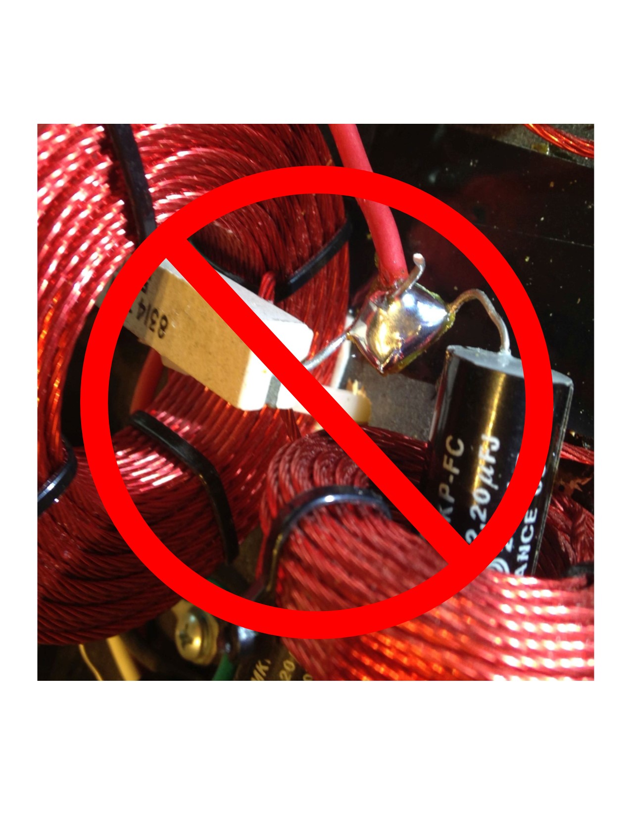
Al, et al---- Perhaps a little math will help us understand the problem with trying to use a mid or tweeter driver below its low frequency design limit. Let's say one measures 100 dB SPL 1 meter from a mid driver/horn combination fed with a 1,600 Hz sine wave. At 800 Hz for the same acoustic output of 100 dB SPL, the driver diaphragm excursion will be? a) the same halved c) doubled d) quadrupled The answer is d. For every halving of frequency, the excursion quadruples. So, going from 1,600 Hz to 400 Hz would require the driver diaphragm to move 16 times farther! An extreme slope network will go a long way protecting a mid or tweeter driver from low frequencies which are outside the bandwidth of the respective driver. Lee -
There's probably nothing short of building a room inside your existing room that will "insulate the sound" from the rest of the house. I'll let you break that news to your wife. :>) Surface-mounted acoustical treatments are either going to absorb or reflect soundwaves--sometimes both! There are a lot of myths surrounding acoustical treatments and their effectiveness. I prefer to use diffusion vs. absorption whenever possible but you might prefer to listen to mostly direct sound with little reflections. Your room shape is interesting and I'm wondering what soundstage issues you are experiencing. If uneven or boomy bass is the problem, first, try moving your subwoofer towards or away from the wall and then laterally and after each new location, listen to program material with clean low-frequencies. If you have access to a measuring mike http://www.parts-express.com/pe/showdetl.cfm?Partnumber=390-801 and software such as Room EQ Wizard, http://www.hometheatershack.com/roomeq/ you will be well on your way to making an informed decision about what bass "treatment" might be needed and where. Ethan Winer makes a good "bass trap" but also has plans on his web site to roll your own. http://www.ethanwiner.com/basstrap.html A combination of listening and measurement will help you get started with the sometimes-frustrating process of turning your listening room into a believable soundstage. If you live in NW Arkansas, send me a PM. I could be persuaded to give an on-site two-cents' worth. Lee Lee
-
Aw shucks. Thanks for the kudos---just trying to get my post count up! Those latest images look very close to what mine look like. Maybe you can comment since you and Daddy Dee have seen mine. Lee
-
At the time I ordered my Klipschorns and center Belle, I was working for Custom Audio in Little Rock. I was able to go to the plant and pick out my horns fronts and even the edge trim and bottom kick board. My fuzzy recollection was the rosewood veneer on my speakers was Honduran, not Brazilian, as there was an import restriction on unfinished rosewood from Brazil. Mine are similar to yours color-wise but the darker grain on mine is wider. Mine have cane grills which makes the rosewood really pop. I'd send you a photo but mine are in storage until our house is complete. Looks like yours will have the lacquer finish. All I used to do was dust them or occasionally use lemon Pledge. Lee
-
My then-new 1979 Klipschorns were oiled Honduran rosewood (KBRO). After a year of having to oil the things weekly to keep the veneer from drying out in splotches, Klipsch (at their expense) redid the finish to lacquer. After that, Klipsch no longer offered rosewood in an oil finish. So, if your new-used horns are labeled KBRL, you have the easier-to-maintain finish. If you have the oiled finish, other forum members might have a good non-yellowing product to recommend to keep them looking like new. Lee
-
50 Years Ago Today, and I was (almost) There
Arkytype replied to boom3's topic in General Klipsch Info
In the early morning hours of March 12, 1960 our family was awakened by a huge explosion. I raced to the window and looked up to see a long silvery object fluttering to the ground. Turns out it was a wing from a B-47 that exploded at about 3,000 feet altitude shortly after takeoff from the Little Rock Air Force base. Three crew members and a couple of civilians perished in the crash. There was a 30-foot wide six-foot deep burning crater in front of a friend's home which was a couple of miles away. Someone said, "There might be a nuclear bomb in there!" Everyone standing around the crater dutifully stepped back a few feet. Lee -
Joe, Users of both the EP1500 and EP2500 have commented (on different audio forums) about the fan noise. Here's a link to a DIY replacement. http://www.hometheatershack.com/forums/subwoofer-amps-high-pass-filters/3658-quieter-fan-mod-behringer-ep2500.html The Behringer design pulls air in from the rear and exits it out the front. You might try reversing the airflow to help attenuate the noise. If your gear is in a dusty environment, I'd get a lower CFM fan, leave the airflow direction alone and install a foam air filter inside the finger guard. Accoeding to the amp's specs, it has thermal protection, so unless the thing is running Class A, I wouldn't worry about using a lower CFM fan. Looking at the photo of the amp's innards, the cooling airflow is compromised by the gap between the fan and the heatsink tube. Perhaps the idea was to have some air moving inside the amp? The Orion brand of fans at Mouser are a great value for the buck---just try to get one with ball bearings--not sleeve bearings. Lee
-
Good sleuthing Gil! I've used the Buffalo Electronics IR repeater system in custom-built lecterns in seven of our classrooms. The AV gear and IR repeater/flasher are rack mounted behind closed doors below and the IR 350 pickup is mounted in the top of the unit. The professor can activate any of the gear with either a universal remote control or the ones for each device. After our seven lecterns were built and being tested, we noticed the IR repeater would work with some units and not with others. We discovered that the lecterns parked under the overhead fluorescent luminaires would not respond to remote commands while those away from the luminaires would. A call to the helpful folks at Buffalo electronics confirmed that the fluorescent lamps were a good source of IR! They suggested de-sensitizing the receiver by removing the dome and partially covering the IR chip with a tiny piece of paper. That did the trick! http://www.buffaloelectronics.com/infrared/ir350.htm While our application involved a short distance, BE claims you can control devices several hundred feet apart. Lee
-
speakerfritz: Actually, the Khorn sensitivity is 105 @ 1 W. DrWho: Based on what data? Is that a trick question? According to the Klipsch website the Klipschorn sensitivity is rated at 105 dB SPL 1 watt/1m. To be more precise, speakerfritz should have included the measurement distance which is currently "standardized" at 1 meter. Before standardization, Klipsch sensitivity ratings were given in terms of voltage and imperial distances e.g. 4 feet. The old Klipschorn rating was 104 dB SPL @ 2.83V @ 4 feet. In actual practice neither Klipsch nor most manufacturers measure their products at one meter with 2.83 volts of a single tone applied to the loudspeaker's input terminals. Lee
-
Btw, the boundary gain doesn't work for speakers with controlled directivity, nor for the Khorn which use the room corner as the final part of its flare. While I agree (in general) with the first part of your statement, I disagree with the second. The fact that the Klipschorn uses the side walls as the final horn flare is a separate issue from boundary "loading" which does work for the Klipschorn and most any other type of loudspeaker. Here's a link to a multiple boundary test done by Pat Brown of Syn-Aud-Con. http://www.prosoundweb.com/article/print/tools_of_the_trade_how_boundaries_affect_loudspeakers Lee
-
Gram, I'm running Windows XP-Pro on three different computers. I just got off the phone with Parts Express tech support. The Windows 7 incompatibility is a known issue and they are working on it. They suggest that once you have WT3 up and running and the USB test lead has been connected for at least a couple of minutes, check the Sounds and Audio Devices Properties to insure that USB Audio CODEC is the default device. Under Advanced settings, check that 16-bit, 44 kHz is selected. Since my last post I've had my replacement WT3 fail initial lead calibration only once out of seven times on a laptop and no failures after 6 reboots on a desktop both running XP-Pro. With the one failure, I performed a Measure Free-Air Parameters test, and then did the lead short/impedance cal and the WT3 worked fine. If you are planning to measure several drivers and their parameters or need accurate resistance and inductance measurements (well within 1% accuracy) and want to avoid the tedium of point-by-point plotting, then I'll conditionally recommend WT3. Lee
-
Gram, I contacted Parts Express and they shipped me a replacement WT3 even before I returned the original! Unfortunately, the replacement unit fails the initial lead calibration. However, if you go ahead and click on "Measure Free-Air Parameters" (with a driver attached to the test leads), disconnect the driver and then perform the "Test Leads Calibration" and then the "Impedance Calibration" the WT3 seems to behave itself. In the FAQ section of the manual, it says a 90 second warmup period is required for everything to stabilize. It also cautions against connecting the test leads to a loudspeaker connected to an amplifier as the DC balance of the WT3 will be affected. The WT3 software can be downloaded so you can see the actual measurements. http://www.parts-express.com/pe/showdetl.cfm?Partnumber=390-804 Just click on the ineractive tour. Now that WT3 is on sale for $79.00, I heartily recommend it warts and all. The time saving alone making precise, repeatable measurements is worth it. I'll contact PE to see what is causing the initial cals to fail. Lee
-
So Just What Was The Meter Reader Up To?
Arkytype replied to BLSamuel's topic in General Klipsch Info
The electric meter reader where I use to live used a monocular to read my meter while standing outside my fenced in yard with "Beware of Dog" sign on the gate. Unless the meter dials can't be read from a distance, there's no reason to enter a yard. The electric utility will periodically replace the security tag holding the meter loop in place. Lee -
Audio Time Delay: Baseball Broadcasts...SOLVED!
Arkytype replied to fini's topic in Technical/Restorations
The need for the delay in the first place is that by the time you receive the game in your home via satellite, cable or over the air, the signal has probably been uplinked and downlinked at least twice using several encode/decode technologies. While an analog signal is delayed only about 0.25 seconds for a round trip to and from a geostationary comsat, the MPEG-2, Digicipher II and other encode/decode technologies used to transport the compressed audio/video signal add up to several seconds of delay. BTW, if you are wondering why your local TV station looks like crap on DirecTV or Dish Network, here's why. In markets where "local-into-local" service is offered by your satellite provider, your market's TV stations are usually received off the air, encoded at a very low bit rate and transported via fiber to the satellite operations centers (SOC) in Colorado and/or California. Some TV stations encode their signal at the station and transport the signal to the SOC via fiber thus bypassing the over-the-air step. At that point, the fiber-delivered signal is decoded, re-encoded and added to the multiple-channel-per-carrier modulators. The local stations are usually transmitted to earth via a "spot-beam" satellite which can serve dozens of markets simultaneously. Since I don't have satellite service, I don't know the status of high definition local-into-local service. Lee -
Audio Time Delay: Baseball Broadcasts...SOLVED!
Arkytype replied to fini's topic in Technical/Restorations
Here's some shareware that will delay the audio up to ten seconds. http://www.daansystems.com/radiodelay/ I suppose if you have two computers, you could load both with the software and connect the delayed audio out of the first into the audio in of the second and fine tune the delay to match the TV coverage. Many radio stations around the country allow you to "listen Live" thru their web sites. So, if the playoffs are out of your over the air coverage area, try the stations in the playoff market. There is a $200.00 device called DelayPlay that is built to solve your problem. http://www.delayplay.com/ Lee -
Joe, I was taught never to discharge a cap with a direct short. In addition to possible pyrotechnics, you will probably damage the capacitor by shorting the terminals directly. Using the time constant formula (T=R X C), a 100 ohm resistor will discharge a 10,000 uFd capacitor in about 1 second. In actual practice, the capacitor won't completely discharge in that short time due to dielectric absorption. Just keep the resistor across the capacitor for a few seconds and then measure the voltage across the terminals. Use a 5-10 watt resistor for safety as the discharge current can be high. Lee
-
For those of you in the NW Arkansas area, there will be a memorial service for Max Saturday, the 18th at 1:00 p.m. at Callison & Lough Funeral Home in Bentonville. They are located at 605 W. Central. Lee
-
Al, Yep, when the main mikes are 25 feet apart and the conductor is in the shadow of the mike's coverage pattern, he's hard to hear! gram, you have pointed out one of many variables when it comes to capturing the essence of a live performance. First, I'll differentiate recording a live amplified band such as the one you heard from an orchestra. Just to take an amplified bass for starters, do you stick a mike directly in front of the loudspeaker, take a feed from a direct box, or set the mike ten feet away to capture room ambience? If you have the tracks to spare, do the first two. You'll usually prefer a blend of the two tracks as opposed to one or the other. Recording a trap set can be as simple as hanging a pair of cardioids X-Y fashion over the ensemble or spending hours miking everything that can produce a sound. According to Chris Morris recording assistant on Fleetwood Mac's album Rumours, "We spent ten hours on a kick drum sound in Studio B." Extreme? Perhaps. But you have to admit their drums do sound good! There are few CDs that are ever going to be recorded using the theoretical 90 dB of dynamic range they are capable of; so what you heard as a live event (assuming the amps weren't clipping) may have spanned 60-80 dB of dynamic range. OTOH, your CCR CDs were probably recorded in their heyday (1969-70)---a decade before CDs were introduced. Not knowing the facts, I doubt they recorded on anything but analog tape and possibly without noise reduction. That means their tapes may have had a 60 dB signal-to-noise ratio at best. If your CCR CD was mastered from the vinyl mastering tape, the dynamic range was manually tweaked downward further. You also wrote, "In that context I am surprised as to many people cite commercial recordings as a reference in evaluating speakers when they are mixed as per the Engineer's preference and based on what room and what monitors he used to equalize, when none of them match up with the system and environment under evaluation." It wasn't until the 1970s that the design of control rooms using other than egg cartons for wall treatment :>) underwent a major evolution. Michael Rettinger's "Acoustic Design and Noise Control" was one of the first non-textbooks written for the DIYer. Chips Davis' Live End Dead End (LEDE) further revoltionized the acoustic space an engineer mixed in. For the first time, using these techniques, a room's acoustic signature could be all but eliminated as a variable in the recording and mixdown process. Peter D-Antonio's brilliant application of Manfred Schroeder's Reflection Phase Grating (RPG) experiments led to acoustic treatment products that can make a wall disappear acoustically. I have used the BAD panels in one of my listening rooms and can attest to the effect of not hearing reflections from a rear wall behind the listening position. http://www.rpginc.com/products/badpanel/index.htm The science of controlling diffusion is a mature one and there are many DIY sites showing you how to roll your own diffusors, absorbers, etc. As for recording orchestral (unamplified) music---well, that's another chapter for another time. Here's a link that chronicles one of the finest (no pun intended) recording engineers that ever lived. Using a single microphone in 1951, he raised the bar way over the heads of the recording engineers who preceeded him. http://www.soundfountain.com/amb/mercury.html My ultimate goal is to have a playback system that is limited only by the source material. With my present system, 30% of my CD collection is enjoyable and the other 90% is tolerable. :>) As I am fortunate to listen to and record live unamplified music a half dozen times a year, I am aware of my playback system's limitations. I could probably double my investment in playback gear and realize an incremental "improvement" but I'd rather feed my other hobbies!! Lee
-
Al, et al Here's a site that has some interesting audio-related animations. http://paws.kettering.edu/~drussell/demos.html Not as dramatic as the comb filtering animation but instructive nonetheless. Al wrote: Another factor is the way modern recording engineers mix their many tracks from multiple microphones down to two tracks. I can only assume that mono recordings from years ago were also mixed down from multiple microphones. It's just another confusion factor! Amen to that! I have the good fortune to record our university's symphony orchestra several times a year in a well-designed auditorium. We use a spaced pair (25' or so) of Neumann M 150 tube mikes and six Neumann KM 84 as "spot" mikes. The eight mikes are recorded discreetly to an 8-track digital recorder and mixed post-event with Digidesign Pro Tools. The typical mixdown session involves establishing a L-R balance with the two M150s and then panning and setting the levels of the "spot" mics. So, from what listening perspective should we mix the eight sources?--- the conductor, front row orchestra, mezzanine? After our last mixdown session this spring, I had a blinding light revelation--why not measure the distance from each of the six spot mikes to an arbitrary center point between the flanking L-R mikes and then (using Pro Tools) delay each mike's acoustic arrival time so that (in theory) each orchestral section near a spot mike would be properly integrated with the main L-R pair. BTW, I usually set my Bruel & Kjaer 1/2" mike about six feet high in the center of the orchestra to measure the peak SPL. So far, I've measured peaks of over 114 dBA SPL during fortissimo passages! Maybe OSHA should be notified??!! In addition to the above recording setup, I also record with a M-S array. While (again, in theory) the orchestra's acoustic output arrives within a fraction of a milli-second to the figure-of-eight and cardioid capsules, the overall realism is lacking. Placement is critical for the best balance and I'll continue to look for the sweetspot. Lee
-
I once tried to clean the front panel of an older Onkyo receiver. After removing all the knobs, I sprayed the panel with 409 and scrubbed it reeeel good. If you haven't guessed what happened, scroll down...... While the front panel ended up all purty and shiny, all the lettering dissolved and ended up in the rag!! There used to be a product designed to full in engraved leters on a metal panel. It was like a grease pencil only softer. Lee
-
Al, Thank you for the heartfelt tribute. I too am saddened by Max's passing. As I read Al's thoughts, I was struck by not only Max's diverse interests (photogrphy, audio, classical electrical engineering) but that he performed all these activities to a higher level than the average person. He was a very good motivator and after only a few minutes on the phone with him, you knew you were going to be researching something he said! As Al can attest, there were no short phone calls with Max! I've had my cell phone battery die during several long-winded but facinating discussions. In addition to audio, he was a fount of knowledge on matters photographic. We had similar digtial cameras and he was always suggesting menu settings to try so I could get better images. When Max was diagnosed with the first of the medical conditions leading to his passing, he called me from Texas to say he wanted to give me his prized Bruel & Kjaer, General Radio and other measurement gear as well as an assortment of drivers and microphones. He wanted the gear to be used and not sitting in a garage. I was overwhelmed by this act of selflessness and felt honored that he would entrust it to me. Since I had already acquired some duplicate Bruel & Kjaer mics and preamps, I decided to pay it forward and sent Al a couple of capsules and a preamp. My hope is that each of the Klipsch Forum members is privileged enough to have a "Max" in their circle of friends. Lee