CANT
-
Posts
385 -
Joined
-
Last visited
Content Type
Forums
Events
Gallery
Everything posted by CANT
-

SOLD-Single H2 components and 2 Heresy I cabinets Chicagoland $200
CANT replied to LotsToLearnCW1's topic in Garage Sale
PM sent -
Nevermind, I found my notes on the back of the KPT-325-N2 outboard network mounting instructions… it was 2ohm before I selected the 3.3ohm replacement. I must have just been remembering selecting that value over 3ohm. As yet another side note… I would suggest anyone with a newer Klipsch network approach capacitor replacement with extreme caution! I did my share of this on the 335’s and a few other models with VERY mixed results! Different is not always better and these networks work and sound good as is.
-
Oh and for whatever else it is worth... I generally power my 325's with a McIntosh MA230. Obviously not a ton of power but I tend to like low power simple amps... I also couldn't imagine needing more than what I have?
-
So, it looks like your 325 networks are an older gen/rev than what I have? They basically appear to be the same other than the build/layout and maybe that 2ohm padding resistor... I tried to find a picture to double check but I swear mine was 3ohm prior to me swapping it out for 3.3ohm? Similar to the the 335's I played around with that value to see if I could pad the HF bit more to my liking/application. If I remember correctly I went all the way to 4ohm on the 335's but I tried several rather small steps when adjusting both. If I can find my original notes, I will confirm whether it was 2 or 3 ohms.
-
I’m kind of curious about the differences between the 396 & 325 networks? I’m guessing it’s either just voicing or cabinet tuning? Or a bit of both? In any case, the 325 is definitely bit simpler. I downgraded my 335’s to 325’s a while back and have been generally happier with the 2way format… I just wished they looked a bit nicer? What I remember of the 335’s, the MF and HF output was noticeably higher than the LF though the HF was really hot (could be read as very detailed). I tried to fix the HF by switching out the 2ohm resistor in its circuit which helped but I ultimately ended up with other issues as well, which is when I started looking into the 325 conversion. My final impression was that the 335 top was really meant to be used with the 904 LF cab if you don’t want to eq the living hell out of it…
-
1740 & 1742 are both bolt on, you'd need 1-3/8"-18??? In any case, I forgot to mention the K702 driver out of my H4 measure 8ohm and is physically identical to the 1748's I also have lying around... though it does look like newer 1748's have changed the cover molding and maybe aren't serialized any more? I don't know, the ones I have are old(er) stock, maybe just try a CDV1-1757 if you can find one?
-
If you are trying to retrofit an older model, you essentially want a CDX1-1748 with 16ohm diaphragm (you'll have to buy it separately) You can look at the spec sheet for the CDV1-1757 to get an idea of the specs.
-
Maybe I missed it in here somewhere but the HF driver is the Celestion Axi2050 correct?
-
I would probably at least use a small Chicago screw per hole? but for the money being discussed here I would think they could fill the holes properly before paint.
-
50/50 now on whether or not to go through with the copper gilding or just give them a slightly better paint job? Also, kind of wish I could veneer the motorboard of the cabs... probably won't ever get around to it though
-
...
-
The wood frame on the 402 looks a bit heavy handed to me, design wise... I'd probably just vote to fill in the unused mounting holes and give it a good quality paint? Maybe a copper gild? It's hard because that horn is so large anything you do is going to feel a bit imposing.
-
“K691 is bnc 75 with a slight mod to the diap.” -Chief bonehead The mod is that it is hardened. The only thing to note about the phase plug is that the P in DE 75-P stands for plastic phase plug. The DE 75-P was used with no K designation prior to the K691 which also has a plastic plug. “K69 was a paudio driver. The k69a has a slightly decreased phaseplug diap spacing” -Chief bonehead I would take this to mean the K69A phase plug shape is largely unmodified from the BM-D750 production model and that the K69 is actually identical.
-
The K28 in whatever iteration it is on should still be the current drop in replacement per Klipsch... I am unsure of what “mixed reviews” the op was referring to? The K28 is a great driver. Klipsch also sells the current KD-15 as a replacement for the original as well.
-
Unfortunately, the number of revisions made to the CF line complicates this line of questioning... Obviously changes were made to nearly EVERY aspect of this line over it's brief existence but what was the difference from one rev to another and what was the purposeful/functional difference between a 63 and a 64, only a Klipsch employee/engineer can/could say. Until something is said, I stand by all of my previous statements... It makes ZERO sense to me, from a production/manufacturing stand point to have 2 different drivers and most of what I see in Klipsch pattern of parts usage says it likely wouldn't make sense to them either. Klipsch likes reusing parts and that's generally a good business practice. Example: The K52 is the same K52 used in a slew of Heresy's, Cornwall's, Quartet's, Forte's, Chorus', KI/KP?KPT Models... over MANY years.
- 31 replies
-
- 1
-

-
- epic series
- cf-4
- (and 2 more)
-
Been meaning see what other people think… The plan was to copper gild the 502’s but before putting all of that work in, I decided to give them a coat of Montana Gold Copperchrome. I wasn’t sure at first… but I think I like it

-
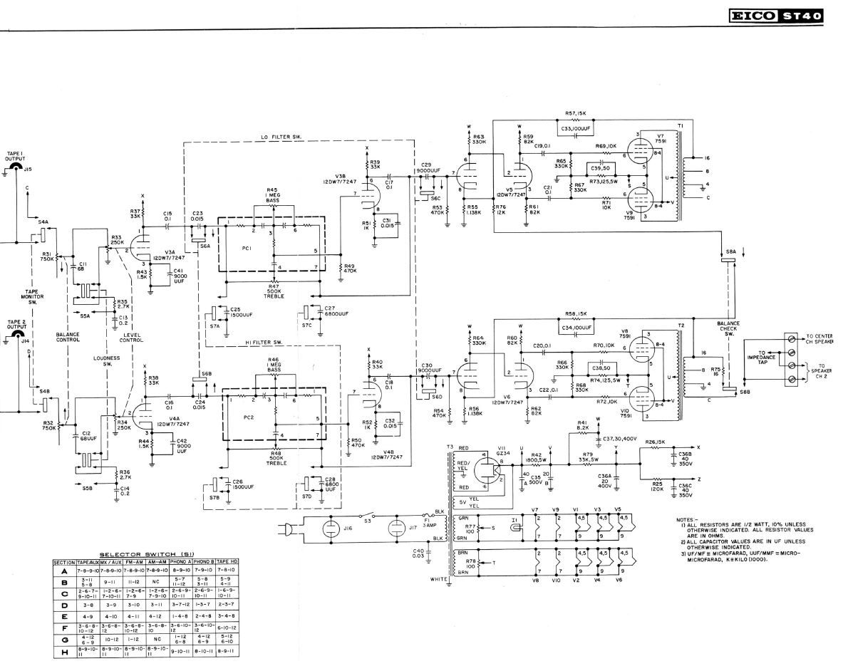
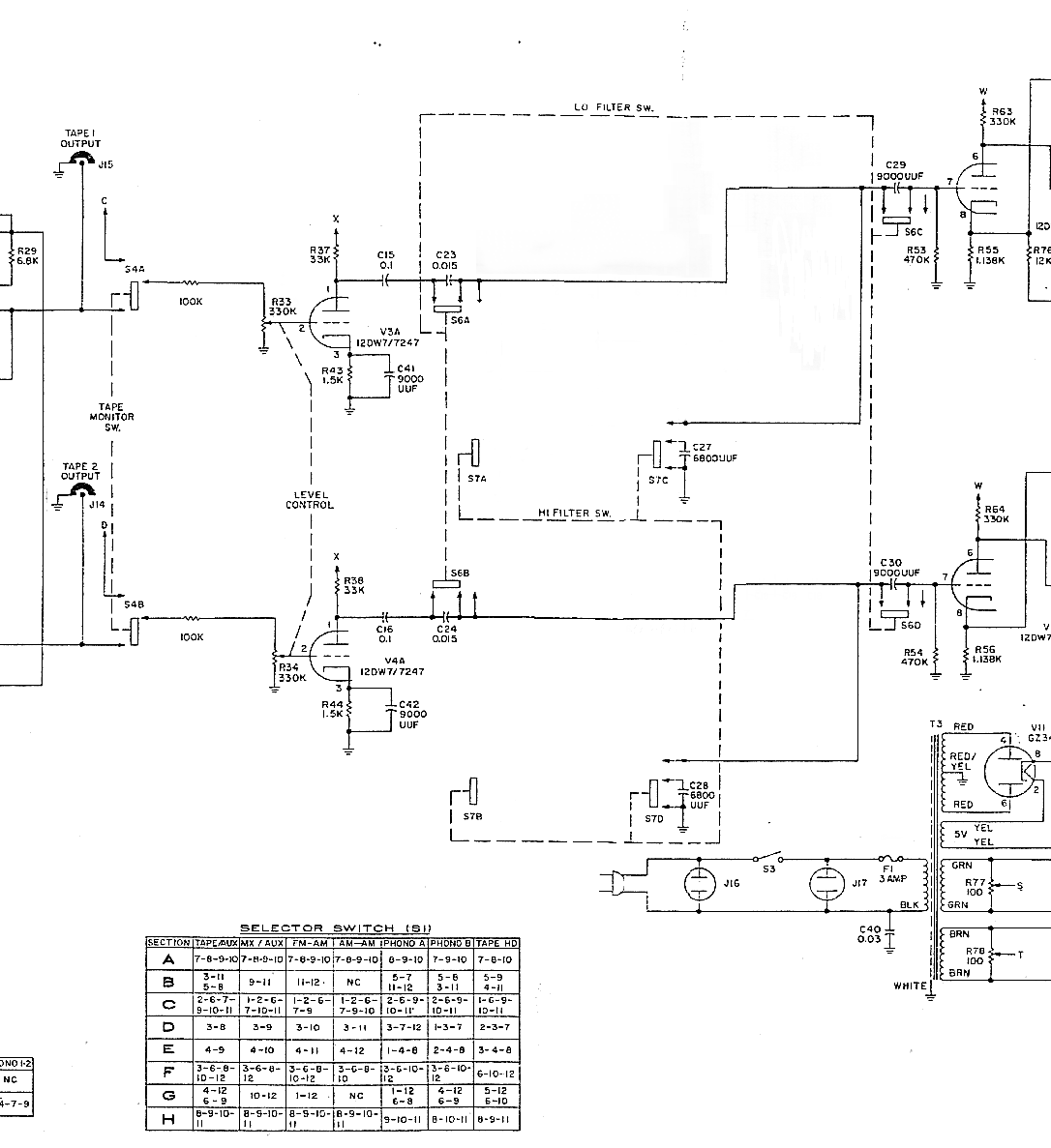
Ok, so what are the advantages or disadvantages to leaving V3 & V4 in circuit if the the tone controls have been removed? The entire front end of this amp was corroded beyond deoxit-ing so if it is going to survive in any capacity, it will be as a power amp... I did buy a pair of 7247 for the V5 and V6 positions to get a rough ideal of its sound but I am not trying to go nuts on parts in case this thing is really only worth its iron. I’ve seen a mod on another site that would mod V3/V4 for 12ax7 duty but it doesn’t make a ton of sense to me because it mostly modifies the already ax side of the 7247? I’ve also been looking over some of the over EICO schem that don’t use this tube like the ST84, HF85 and 81 just to get an idea of their thought process. I guess I was thinking worst/best case it could run similar to a Dynaco ST35 just off the single 7247 but maybe I am misguided.
-
They generally just request that you supply the SN of your speakers... https://support.klipsch.com/hc/en-us/requests/new I've ordered several replacement parts from them
-
I recently picked one of these up without tubes (for cheap) and was planning on running through it this weekend if I have time... My question is related to the 7247/12DW7's... I don't have any... but I do have AX's, AT's and AU's... what is my best choice for a sub for testing purposes? I've looked around online for help but many/most of the info I can find tends to lead to privately hosted links that are long dead. Side notes: My love of old switches and pots lives on (sarcasm) so expect most of them to be removed. I did located a gentleman who removed the tone control function (see ST40-mod-A4) though he left the Hi and Lo filter switches that I have no desire to use. This this amp is definitely no show pony so I am unconcerned with keeping it original. Thanks again for any help you can provide
-
Just so that this thread isn't left completely open ended... the issue with the one amp I was having was the Damping Factor Switch, which I ended up removing from both amps. Everything appears to be operating great now!
-
I'd like to thank everyone who's replied so far for trying to help... Work has been very busy and I've had and still have some family matters on my plate so this is realistically on the back burner for now. The other night I did tinker a bit just to clear my head of other things.... Currently both amps are now set to use C28 (0.033uF) going to V4 as the input. I have also completely disconnected the front end of the amp. It's hard to explain on the schematic but they actually made this rather easy on the chassis. This disconnected R57, removing C3, all the preamp heaters and the incandescent light on the front panel. I partially did this because it is near impossible to check the voltages or anything else in the power amp section without separating the 2 halves of the chassis. I also wanted to give this idea one more shot after realizing the amp I originally tested was not functioning properly. Well, on the good amp this setup sounds amazing, even on just an ok test speaker! Previous there was, what I would consider, a tremendous amount of noise. Currently the amp is so quite I didn't think it was working the first time I turned it on to test it. The malfunctioning amp makes some noise on power up but does quite down now and has about half of the output of the good one??? There are so few components left I am curious what would likely cause this? I did swap both the 6BA8A and the 5Y3GT since they were purchased as NOS but may not have actually been but the problem persisted. I guess I will check everything else when I eventually have time... Side Note: since none of these Sherwoods seem to be very popular/well known I thought I would mention that I got this whole idea from another one of their models, the S4400 & S360. The S4400 was a stereo pre with a mono power amp and you could buy the accompanying S360 to make it fully stereo. I guess this wasn't a popular setup at the time because the S360 is exceedingly rare. The S4400/S360 uses a 7199 instead of a 6BA8A and 4x 7189 instead of 4x 6BQ5 or 2x 6L6 used in most S1000's but other wise seem pretty similar. I actually have a schem for the 4400 but haven't been able to get my hands on a 360. At times, 4400 owners have had an easier time getting a hold of a second 4400 or a 7189 driven S1060 to convert and use as an S360 which made me think maybe I could do that to the 1000's I had lying around and just use my own pre... S1060_schem.pdf S4400_schem.pdf
-
Ok, so I used the tape input with its 100K to ground and placed a 0.01uF behind that with pigtail... Amp A: Disconnecting C25 (.022) from V3 pin 7 (grid) and attaching the aforementioned pigtail everything seemed to work quite nicely. The volume pots on both amplifiers are trash so it was good to see that they could be bypassed. Amp B: Disconnecting C28 (.033) from V4 pin 7 (grid) and attaching the pigtail everything worked but with much less volume and missing bottom end. After reworking this amp B to match the wiring of amp A, I notice that while the volume was better there still seemed to be an issue? The very top end of the output is distorted and still lower than amp A by a little bit? Both amp have had all electrolytic and paper caps replaced (they more or less match). They are also both running NOS 5Y3GT's, NEW matched 6L6GC's, NOS 6BA8A's and NEW 12AX7's. Any ideas on what would cause the distortion/low output? Also can some one tell me what function R54 (240ohm) and C1 (50uF) are performing? When going through the amps I notice one had a 270ohm and one had 300ohm (technically 270 + 30) in the R54 position... I have a schem for a similar Bogen MO30 that uses 200ohm and 50uF... I'v also seen schem at use nothing at all in this position... what does changing the value of the resistor or cap do? Thanks
-
I’ve had the fewest issues with Sonicaps and ClarityCap SA/ESA/CSA... in the old Klipsch filters I tend to like Obbligato Film and Foils too... but I tend to hover I the low to mid priced area. I will some times also use Daytona .01uf film and foils as a bypass... I am not sure why but the will smooth things out at times.
-
I’m not really familiar with Audio Asylum and when I went to check it out I would say I found it easy to navigate... I do realize that the Klipsch forum prob isn’t the best place to ask for this advice but I figured it was worth a shot? I am mostly interested from a general stand point, is it possible to jumper past the eq section? Like run a wire from one of the rca jacks straight to the loudness/volume pot? Could I just leave the other half of V3 unused? Or run a wire from the tape/monitor switch to pin 2 of V3 and throw like a 1M resistor to ground in there? Even better would be to remove C28, leave R40 and use that as the input... bypassing V3 altogether? If this were SS I would have better idea of where I could jumper in to the power amp from but I am just not very knowledgeable when it comes to tube amp design.
-
I haven't really delved all that much into tube amplification but I have a pair of Sherwood S1000's that I've been wanting to use/try out in a stereo setup for some time... Ideally I would be looking to use them as power amps solely. The amps have a tape monitor switch that bypasses V1 (Phono Pre) & V2 (Pre/Cathode Follower) completely but leaves the tone controls and volume in place... I am curious what your thoughts on bypassing those functions are? These amps appear to have been changed/revised quite a bit over their production so it may not be exact but I have included what I feel is the closest version of the schematic I have. Thanks Sherwood-S1000-II 6BA8A 6L6 Schematic.pdf