captainbeefheart
-
Posts
1422 -
Joined
-
Last visited
Content Type
Forums
Events
Gallery
Everything posted by captainbeefheart
-
Wow V13 was really loose looking!! Can you take the tube out of the socket, specifically V13 because that seems to be the worst one and snap a hi-res photo of just the socket for us to look at? It will also allow me to put it into photoshop and show you how to properly re-tension it. Is there any noise when you wiggle them like that through the speakers? I personally wouldn't want to ship an amp around the country like that, or transport it much at all honestly. It is really simple to re-tension the sockets yourself and you will be back listening to music before you even box that thing up to bring it out for repair. Screwdrivers work, I use a conjunction of a metal pick and small screwdriver. Leave the amp off and unplugged for a good half hour before doing this to make sure the voltage has bled from the capacitors.
-
Alan Eaton 45 Monos with Heresy
captainbeefheart replied to angelaudio's topic in 2-Channel Home Audio
When you have been into this hobby both as a listener and as an engineer as long as I have you end up with a pretty good idea of what you like and don't like. I have had the pleasure of hearing lots of systems and all kinds of different gear. Understanding the technology in and out also helps me weed out amps so I spend less time trying out different amplifiers and more time listening. I don't expect the average person to learn theory and study circuits and topology but that is what I am interested in so I get into deeper than many. Specs can be deceiving but also can tell you a lot if you know how to interpret them. High power at low distortion just doesn't tell you much about how it will sound so diving deeper into details is the only way for me to really weed out amps I will audition or build. Let's face it there are A LOT of options with many "fanboy's" in their respective corners peddling their wares. One thing that always bothered me about the Alan Eaton 45 amp is there is a 6SN7 each per channel yet he only uses one triode inside the envelope per channel. Using that other section that is already there and being wasted as a follower to drive the 45 into A2 operation would be quite easy and drastically improve the amp's performance. Or at the very least just tie the two sections in parallel to reduce noise and output impedance. Or if you really just want the circuit exactly as it is just use a single 6J5GT per channel which is the same as a 6SN7 just one section per bottle, no wasting a nice matched 6SN7 to only have half of it wear out from use and the other triode is still new strong condition. Such a waste IMHO -
I really was into the Corn-Scala but ended up just keeping the La Scala's with Active Sub-woofers. The preamp drives the mono's for the La Scala's and from the pre "sub-out" to the active sub-woofers. I really only recommend the La Scala with a separate sub-woofer because although the horn woofer is tight, it only is good down to 50Hz or so. The sub gives that kick in the chest thump no there with the La Scala's alone. I don't think just a Corn-Scala will quite get you there, you really need some power and air movement down to 20Hz for that shake the house bass feeling. You can get there with a horn sub-woofer but it would have to be enormously large.
-
A little history for anyone not in the know. The 6A3 is a 6 volt filament version of the famous 2A3 DHT. The 6B4G is an octal base version of the 6A3. Early 6B4G replacements were 6AV5GA tubes internally connected screen and plate relabeled as 6B4G because they knew the triode strapped 6AV5GA will perform identical to the 6B4G. So basically the cheap triode wired 6AV5GA is a great alternative to using 2A3 DHT tubes. I actually have one old 6B4G marked tube that is really an internally triode wired 6AV5GA sweep tube.
-
The input impedance of the power tubes is set by a resistor value not the actual tubes, this is for Class 1 operation like the majority of amps. Class 2 operation can operate the power tubes into grid conduction. So the drive requirements for two tubes in parallel is the same as a single tube. Tubes are voltage controlled devices unlike BJT's which are current controlled devices, beta multiplies base current into collector current. A tube changes plate current proportional to it's grid to cathode voltage. This is what we are changing really when driving a tube is the grid to cathode voltage. Yes a 12AT7 is plenty fine driver for a single KT88 or two in parallel. Yes, for the most part a tube with low plate impedance and high transconductance is going to perform better into tougher loads vs a high plate impedance low transconductance tube. You can see from the very first triodes made up too the sweep tubes for TV's that they originally had very low transconductance and as time and technology advances you see the height of tube technology with amazing characteristics. A large majority of us tube nerds actually build amps with TV sweep tubes because they are vastly superior to standard audio receiving tubes. This is mainly for pentode type performance where they really are incredible. Of course they can be wired like triodes also, for example if you wire a 6AV5GA as a triode they have practically identical properties as a 2A3, some actually came wired as triodes for direct replacements for 6B4G.This is well known in underground tube engineer networks where you can make an amazing push pull triode power amp that sounds like an expensive 2A3 push pull amp but instead using $3 6AV5GA sweep tubes. The reason many use transistors for driving tubes is because if you want to have the best performance you want direct coupling into Class 2 operation. Transistors are superior at delivering a low impedance source to drive the tube grids into conduction without wimping out.
-
Sorry it was a typo, I went and edited it to say "less veiled" 🙃
-
The easiest way I can explain it is first in the two tubes rolled up into one model, since the transconductance of each tube sums to the total transconductance the net "new single" tube model can possibly have less total transcondcutance so less current, less power and gain. Example both tubes should have a gm of 10mA/V but one is on the low side of 8mA/V, total gm is now 18mA/V instead of 20mA/V. One tube is working harder passing more current vs the other. Or thinking of it reciprocally the weak tube is holding the rolled up lump sum "singe tube" back, they are not working together well to form the optimal single tube model. When speaking in terms of how things sound, well to my ears when I take the time to match tubes very precisely for parallel use the total sound is less veiled, with better sound stage and imaging between instruments and vocals. For example I purchased a box of 50 power tubes for my amp which gives me the means to get really good matched pairs for parallel use. On a side note, the 2A3 tube is actually two 45 tubes in parallel inside one bottle. Take a look at the datasheets, the 45 has rp=1600 and gm=2500uMhos (2.5mA/V). The 2A3 has rp=800 and gm=5000uMhos (5mA/V). Neato
-
I did not mean to say the amp cannot run those tubes, everything has trade offs so I was more interested in what is gained and what is lost changing power tubes. My guess the better bass is from the lower output impedance but since the KT150 is much less linear I am curious to see a distortion vs frequency plot between the two tube types because often higher even harmonic distortion at low frequencies can be confused with more bass. I presume it is the lower impedance and increased current that with the KT150 that is giving you the better bass performance. BUT, is the midrange and top end as nice compared to the KT88? Has anything else changed besides the better low end? I am in the camp where I feel one tube is optimized for an amp and whichever gives the better overall performance is what should be in there.
-
Alan Eaton 45 Monos with Heresy
captainbeefheart replied to angelaudio's topic in 2-Channel Home Audio
It is not difficult to make a 45 amp that can deliver the goods with complex music but unfortunately the vast majority of builders just copy old schematics and feel that the 45 tube amp has to have these cons which sadly isn't true. What you want to look for primarily is a SET amp that operates in Class A2 mode, this is a huge advantage. Also many that build these amps are scared of feedback, but just a little bit of properly applied feedback will not ruin the sonics and bring the performance level up to where complex music can be appreciated and also have a damping factor >100 to boot. But sadly many just do not put forth the extra effort to address these issues but when you do find one it is the best of both worlds. -
Great questions but not easy to answer in way many will understand, I will try and explain as best as I can. With power tubes in parallel, specifically a Class AB push pull amplifier like you are discussing you want them to be matched for both bias current and transconductance. For bias current, if they are not matched the issues will be most apparent at higher powers and transients. Let's say you have two KT88's in parallel and they should be biased at 60mA, if one biases up at -45v grid to cathode while the other needs -40v, when signal is applied the one that is biased at -45 it can reach cut-off (no current) sooner and the one biased at -40 can reach grid current sooner. The latter being the most likely, this means the one tube that reaches 0v grid to cathode sooner will draw grid current clamping off the signal at both grid and plate output while the other is still in circuit. As for the one more negative, -45 if it reaches cut-off sooner (no current class B ) it will also drop out of circuit. Both conditions will cause the amp to wimp out at higher powers as now one of the parallel paired tubes is no longer in circuit and you just have one tube driving the load and not two. Transconductance will effect all performance, the tube with a higher transconductance will pull more current through the tube for the same swing grid to cathode. This issue has a whole host of problems too complex to explain here. If you want to parallel tubes lets view them as a one tube model because that is what is happening. The parallel tube's mu stays the same so you do not have to worry about the drive signal working any harder with two tubes in parallel vs one single tube. Input impedance is set by the grid leak resistor and since mu is the same the two parallel tubes will require the same amount of swing to bring to full power as the single tube. So what happens when you parallel two tubes? The model would be one tube except the transconductance is doubled and the internal impedance is halved. Since; mu=gm*rp gm=transconductance rp=internal plate impedance when you double gm and halve rp you can see how the math proves mu is exactly the same. The benefit is you now have a "tube" that has double the gm, which means it pulls twice the current for the same deltaV grid to cathode as the single tube. Example, gm=10mA/V, for a deltaV of 1v grid to cathode you get 10mA delta plate current. With them in parallel the gm doubles to 20mA/V so for the same 1v delta grid to cathode you get 20mA delta plate current. So for the same signal swing we are moving double the current through the load. It's as simple as that.
-
Alan Eaton 45 Monos with Heresy
captainbeefheart replied to angelaudio's topic in 2-Channel Home Audio
The 45 directly heated triode is one of the most amazing tubes out there which is why it is one of my personal favorites of all time. I like the simplicity of the Alan Eaton 45 amp and it has a classic DHT amplifier sound to it but there is major room for improvement. I know what you are going to say, simple is best and I agree with you 100% but hear me out first before scolding me. The 45 triode like many popular vintage tubes are dwindling fast and the nicest specimens are starting to cost a lot to purchase. Luckily they are currently making new 45 tubes but the good ones are quite expensive also. My thing, get your hands on some NOS and in a well designed amplifier will last a very long time if not your whole life. Any major piece of laboratory equipment that needs to power filaments, lets use a mass spectrometer for example will use a constant current source for power. Why because the replacement parts are expensive and they do not need their expensive lab equipment to break all for a simple filament blowing open like a light bulb Almost all failures I see from DHT audio tubes is in the filament. When it is not powered up and cold the resistance is really low, when hit with a voltage source it will draw a huge in rush current which damages the filament eventually burning open the weakest spot in the filament causing the poor tube to be thrown away with plenty of emissions left, just sad to me. A constant current source keeps the current constant and voltage changes with resistance, so as the filament gets hotter and increases it's resistance the current source too increases voltage to keep the current constant keeping tubes happy and healthy and so you will not have to throw a lovely rare DHT in the trash prematurely. This is nothing that will drastically drive the cost of the amplifier up, maybe $20 in parts we are talking about. Driving a DHT. What do I mean by that? Many of the DHT tube require a fair amount of swing to reach full power, say 100v peak to peak compared to an EL84 which is more like 20v peak to peak. But, more importantly with such low powered amplifiers is transients often swing the output triode close or past 0v grid voltage which draws grid current. The whole AC coupling between stages causes a bias shift and blocking distortion, not great for hifi audio. So you want a low impedance circuit which can deliver current to the 45 control grid. The most popular method in the days where these tubes ruled the world was an interstage transformer which Alan Eaton chooses not to use, he AC couples the stages via a capacitor which causes the aforementioned issues during transients. The other issue is the large swing needed to drive them will make the amplifier already have excessive distortion in the driver stage alone where most amplifiers the majority of distortion is from the output stage. Now I am not a person that requires in the parts per millionth (10^-6) distortion figures but I still like to keep hifi amplifiers clean, say between .1-1% THD at full power mostly second harmonic sounds great and anything more will muddy the sound with complex music. Another problem is output impedance, most of these DHT amplifiers just cannot properly drive our beloved Klipsch loudspeakers, the high output Z just follows the impedance curve and many times with non horn loaded woofers types like Heresy's cannot control the woofer properly. The amp was lovely with simple music, jazz trios, piano, vocal, chamber etc.. all were lovely but when we tried playing pop music, anything from Jay-Z to Pantera, Michael Jackson to Nirvana, Pink Floyd to Beastie Boys the amp just did not hold up well. -
Voltage rating will not have any sonic attributes.
-
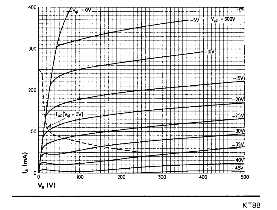
I am curious what you think of the KT150, yes you can get more power with the KT150 vs the KT88, not sure what the increase is with the PL amps but to gain +3db in sound pressure from the speaker you need to double the amplifiers output power. In this case there is no way the power will double so the actual increase in power is negligible to the ear, just a hair more headroom at most but the plate curves for the KT150 is just plain awful, much worse in linearity vs KT88. Luckily this amp uses a fair amount of negative feedback to clean things up but starting with a more linear device is always best. Here are the output plate curves. You can see how wobbly the KT150 is yikes!! Also note that KT stands for kinkless tetrode, the KT150 curves clearly show the negative resistance kink, definitely not good for audio and bias well away from that area.

-
Ideally when you have a resistor application where it will be getting hot you want to lift the resistor above the circuit board with extra lead length so air can get all around the resistor and reduce heat damage to the board. I doubt the ceramic resistor is bad, you shouldn't have to replace it just remove, increase lead length, and reinstall with a space between it and the board. Another option is to replace the resistor with one that is meant to be mounted to small heatsink that way it can dissipate a lot of heat and never get hot. Typical 50 watt heat sink versions are very affordable and so are the heatsinks. As for the capacitors I doubt you will benefit from replacing them. People have a fear of electrolytics but in this application there is no benefit to going with film unless you want them to last forever. The electrolytic can become high ESR for high frequencies which you do not want here, you want a low impedance for high frequencies to filter them out of the woofer circuit. If you crunch the numbers though even slightly high ESR is nothing to lose sleep over unless the capacitor has gone completely belly up then you will benefit from a fresh capacitor. The ESR in these caps is much less critical vs the ones in series with horn and tweeter where you will begin to get losses across the cap with too high an ESR. I have been engineering electronics for critical application almost my entire adult life and am in the camp where there is no benefit from changing to film, the high value capacitance in small package is great for this application, if you do end up replacing just choose a high quality Nichicon, or Panasonic that is rated for long life, typically 10,000 hours @ 105°C.
-
I doubt it is the actual sockets but anything can happen, if it is just the female part of the socket you can use small jeweler screw drivers or better a dental or mechanics pick and re-tension the sockets to fit tight again. You can also have a bad solder connection to the tube sockets that after removing and installing has altered the connection. Since all of your front end tubes are 12AU7, it sounds like you took the two high gain tubes (3&4) that are the most crucial to noise and swapped them to tubes 5 and 6 which are phase inverter and driver where noise is less critical to the circuit. The first stages have more gain and also any noise is multiplied by gain further down the line. So it sounds like to me you have a noisy 12AU7 tube that you moved to a less critical section of the circuit hence the noise is less than what it was. I recommend putting the tubes back to how they were originally and while the amplifier is on tap the side of each tube with a chopstick or wooden pencil, this may make the noisy tube easier to find and just replace it. Also while it is on give each preamp tube a wiggle and listen for noise, do not pull it out of the socket just gently rock it side to side in the socket. So probably just a noisy microphonic tube, these amps have the autobias feature which I have seen many fail and have to be repaired, you may just want to bring it to a good tech to have the whole thing looked over while it is in there.
-
Sounds to me like arcing, that crackle and pop, bacon in frying pan sound when a resistor starts to internally arc. Could also be just a bad solder connection arcing or even a tube/tube socket. This often happens to plate load resistors especially if chosen near it's limits. Many engineers feel it is ok to run a resistor near it's dissipation limit, I will say depends on application but for a high quality amplifier a good engineer will choose plenty of headroom, I like at least 5x preferably 10x. For example you have a plate load resistor dissipating 100mW, I personally would use a 1 watt plate load resistor (1 watt) but 1/2 watt (5x) would be ok. I have seen way too often 2mA of current on a 100k plate load resistor, this dissipates 400mW and they use a 1/2 watt resistor. Yes technically it is within the maximum limits but depending on the temperature coefficient it could change values drastically and also fail sooner. If you are careful around high voltage open her up and poke around with chopsticks until you hear the arcing noise become worse. Wiggle everything you can and keep one hand behind your back or in pocket while doing this.
-
Which specific Fisher amplifier are you using and what is it's service history? How long and what type of speaker cable are you using?
-
Wow lot's of work great job! I had one of these a long time ago and ended up doing major surgery as well. Looking at the schematic had me thinking it wasn't worth wiring back how it was originally so I decided to keep the same tube compliment but shifted things around a bit. I moved the 12AX7 to the input stage and wired the 12AU7 as a long tailed pair vs the original paraphase splitter. What is your experience with the CE multi-section capacitor cans? I am in a few different antique and ham radio groups and many of us had bad experiences with them. I don't purchase multi-section cans much anymore as I prefer now to just very carefully open the crimp around the wafer and pull the guts out. The machine shop lets me set up a lathe to spin the cap slowly while the tool slowly opens the crimp. I then stuff with high quality caps, it's amazing how small they have become over the years to allow this to happen. Many in the group also do this but use a tubing cutter to open the can but this often leaves clues that the can was once opened. I am going to be following this thread definitely.
-
Hey take it easy on me I'm new here 🙃
-
Where are you located? I am near Boston and have a nice set of La Scala's if you want to hear them.
-
I must have missed that part where you mentioned that. There have been times where I though a switching supply for a woofer was bad but when I tested them under my own loads they were fine and had to move on to the amp circuit that was faulty. Just giving people advice to check power supplies under resistive loads as a troubleshooting step.
-
KP-301 (3.0B) Crossover - What is this?
captainbeefheart replied to geoff.'s topic in Technical/Restorations
You need to take the resistor out if you are going to take the polyswitch fuse out. The polyswitch is of very low resistance when at it's normal operating currents, when a fault is detected by increase in current the polyswitch increases it's resistance to reduce current and protect the tweeter. When the polyswitch is at normal current and normal operating conditions of low resistance it being in parallel to the 200 ohm resistor will pass almost all of the normal operating current. If you just remove the polyswitch you will have 200 ohms in series with the tweeter seriously reducing it's output to almost nothing. -
It is a TRS type 1/4 jack. It gives the option of using balanced or differential type electronics with common mode rejection for better noise control. +/- are the two phases for signal and the other is ground for use with xlr or balanced mic type cables. You do not have to set it up like that if you just want to run normal single ended. Just use regular RCA cable and tie the - and ground together. Tip would be + and ring/sleeve would be tied together. It's either that or they give you the option to separate signal - and safety ground to reduce noise using shielded speaker wire. In which you can just do the same as above with regular speaker wire, just tie ring and sleeve together for negative. You may have to open it up and take a look.
-
TLC for Klipsch Chorus II (mid 1990s)
captainbeefheart replied to gabuchan2's topic in 2-Channel Home Audio
There is one capacitor in the woofer circuit that is not critical, the earlier crossovers types like the AA never even had one there and people love those crossovers. I highly doubt it is a capacitor problem to be honest. The type there when fail usually dry up and kinda stop working which don't cause much trouble like the symptoms you describe, unless they short but that would be extremely rare in this application. You can even take that capacitor out of the circuit as a troubleshooting step to see if it is causing problems but I doubt you will notice much. Should be the one marked 68uF and it looks different from the others as it is an electrolytic type. Does the bass sound bad at all volumes or only at high volumes? Is it all bass or just some bass notes set off bad sound? -
The holes in which to poke with what is said in their supposed technical explanation are vast. First very simple issue would be the term resonate, while yes objects do have a resonant frequency it is all but one frequency at which this phenomenon happens at. If when the stylus vibrates the record at the specific resonant frequency of the wooden clamp what molecules are released? How are they attracted back at the cartridge? Even IF there was some molecular interaction with the air around the clamp it would be at the resonant frequency. I fancy they are implying the interaction is physical not electrical akin to pressure waves expelling out from the clamp, it is strong enough to reach the cartridge and vibrate it again? Why don't we then hear this resonant molecular wave pulse? And again it would only occur at the resonant frequency so how does one frequency help? So now you have one random frequency most likely so high you cannot hear it being amplified through your gear? This ultra high resonant frequency would most likely wouldn't even make it past the first amplification stage as us engineers do set an upper frequency pole on purpose for stability. I try seriously to give anyone the benefit of the doubt on these claims but almost always they are never proven and shown to do the things they say they do and physics usually just tells us this can't happen or it plain old just doesn't even make sense in our predictable Newtonian physics world. Anyway thanks for a good laugh!!!