mboxler
-
Posts
574 -
Joined
-
Last visited
Content Type
Forums
Events
Gallery
Everything posted by mboxler
-
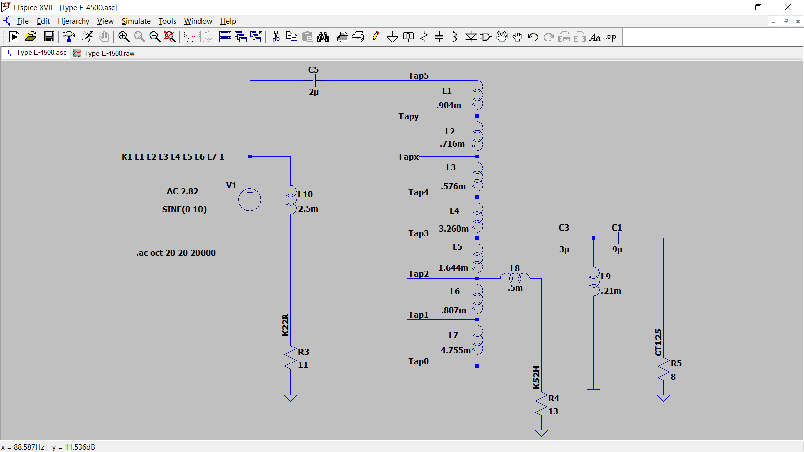
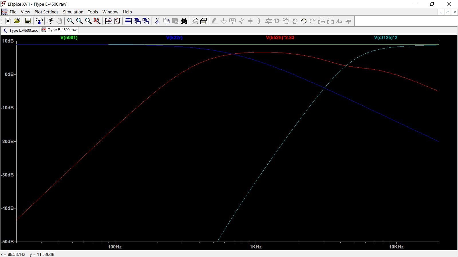
Here's an E-4500 crossover I've simulated but not built. I was going to use the CT-125 tweeter, though. The T2A autoformer is also replaced with a simulated 3636, using the same taps. Not sure how safe it would be with your EV tweeter. Now you got me thinking about building a pair. Mike Mike

-
ALK CSW Universal Crossover Capacitor Question
mboxler replied to Heaterman's topic in Technical/Restorations
Hey Mark Although not nearly as knowledgeable as Dean, I'll try to answer your question. The purpose of the 10 ohm green resistor across taps 0 - 5 of the autoformer is to keep the load on the high pass capacitor to around 8 ohms. To keep it simple, let's identify the crossover point to be the frequency at which the impedance of the high pass capacitor equals 8 ohms. I use this calculator to determine that frequency. http://www.pronine.ca/capimp.htm If you enter 47uf in the capacitance field, and 8 ohms in the impedance field, you get 423 Hz as the crossover frequency. 49 - 50uf gets you close to 400 Hz. 40uf gets you closer to 500 Hz. If you enter 33uf, you get 603 Hz. Keep in mind that this is a gentle slope electrical filter. Acoustically you may like the sound of a 500 Hz capacitor in a 400 Hz horn. Hope that helps! Mike -
Heresy crossover mod, back from the dead
mboxler replied to Tom Mobley's topic in Technical/Restorations
Non-inductive resistors are recommended, although the error of an "inductive" resistor will generally not be apparent in the audio band. I can't see a reason why that resistor wouldn't work, although I use these across the autoformer. There is an 11 ohm version if that's what you want. https://meniscusaudio.com/product/10-ohm-10-watt-mox/ Mike -
Apologies, @sootshe, but I have a question for @Deang I modified the Type A/AA illustration with a hybrid approach for the 3636 / 10 ohm shunt resistor. By placing the resistor on the 3636 side of the capacitor to common, the intended 1 db attenuations of the 3636 can be utilized. This , too, represents a "Constant Impedance". Connect tap 0 to common (input '-' and squawker '-'). Connect capacitor (with shunt resistor) to tap 5 (+0 db), tap y (+1db), or tap x (+2db). Connect tap 1 (-12db) , 2 (-9 db), 3 (-6db), or 4 (-3 db) to "output " squawker '+'. I know you feel that both "outputs" to the squawker must float, but I don't understand why? I like the ability to get attenuations in 1 db increments. Thanks, Mike
-
OK, I'm stupid....need help with layout from schematic.
mboxler replied to sootshe's topic in Technical/Restorations
It's unfortunate that the terms Plus and Minus. Positive and Negative, and even Ground worked their way into speaker terminology. They are either misleading or flat out wrong. I wonder if you changed the crossover input and output labels from "+" and "-" to Red and Black? The only purpose of the labels is to help with the amplifier and driver connections. Perhaps things will be a little clearer??? Mike -
OK, I'm stupid....need help with layout from schematic.
mboxler replied to sootshe's topic in Technical/Restorations
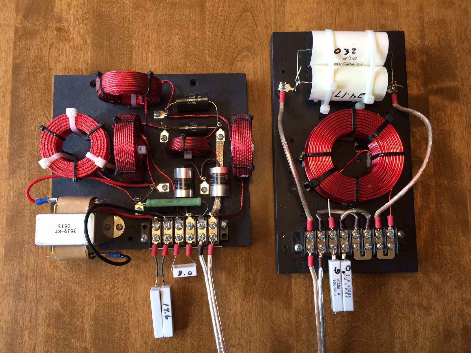
Sorry, but I don't seem to follow, unless you want to connect tap 0 to input IN- ? That wouldn't hurt, but tap 0 is already connected to the common bar at Mid+. Let's say you do. Connect IN- to tap 0. Connect the "output" of the .2mH inductor to either x,y, or 5. Two connections I drew 4 possible connections "above" the 3636 indicating either 1,2,3,or 4. Connect this wire to Mid-. Connect tap 0 to Mid+. Two connections. Regarding the crossover photo. It's hard to tell from the 3619, but it appears that... Tap 0 to common Tap 5 to inductor and Mid + Tap 2 to Mid -. So, input 0 - 5, output 2 - 5. Not your normal connection, but if my calculations are correct, you get a 1.546 turns ratio, (3.78 db attenuation), and phase reversal. It will work, but attenuation levels of taps 1 - 4 are not standard. I'm not sure how to wire the 3636 that way. Sorry I'm not helping. Mike -
OK, I'm stupid....need help with layout from schematic.
mboxler replied to sootshe's topic in Technical/Restorations
Looks like the output to the squawker is inverted, so think I allowed for that in the attached. The "output" from the .2mH inductor should connect to Tap 5, x, or y, as well as one end of the resistor. The other side of the resistor to common (tap 0). Mid - should connect to Tap 1, 2, 3, or 4. I moved the common bar connection from Mid - to Mid +, so that Tap 0 is always connected to the common bar. So, for -6 db, input 0 - 5, output 3 - 0 . Hard to tell, but the pictures show only three wires attached to the 3636 as well. Tap 0 is both input and output and connected to common. I reserve the right to disagree with myself later, but for now this seems right. See what you think. Mike
-
OK, I'm stupid....need help with layout from schematic.
mboxler replied to sootshe's topic in Technical/Restorations
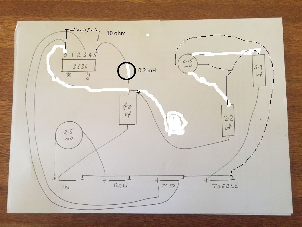
More like this. I missed something earlier, and deleted the wire from the "top" of the 40uf cap to tap 0. Sorry for the poor "Paint" job. I may find something else after my coffee kicks in.
-
OK, I'm stupid....need help with layout from schematic.
mboxler replied to sootshe's topic in Technical/Restorations
If you know what mid driver you will be using, and you want the ability to attenuate the tweeter, remove the .2mh inductor from the input, and we can calculate it's replacement and position it between tap 3 and the mid driver. Now, if you want to attenuate the tweeter by 3db, attach the 2.2uf cap to tap 4 instead of tap 5. -
OK, I'm stupid....need help with layout from schematic.
mboxler replied to sootshe's topic in Technical/Restorations
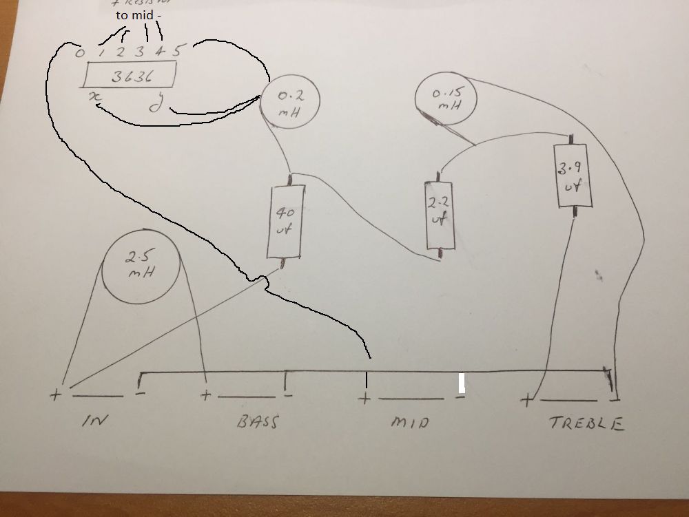
The .2mh inductor needs to be in series between the 40uf cap and the 3636, like you have the .15mh inductor between the 2.2uf and 3.9uf caps. The .15mh inductor should not be in series with the 2.2uf and 3.9uf caps. Connect the two caps together, draw a line from the middle of that connection to one side of the .15mh inductor, then connect the other side of the .15mh inductor to common. Place a 10 ohm resistor across taps 0 - 5 of the 3636. -
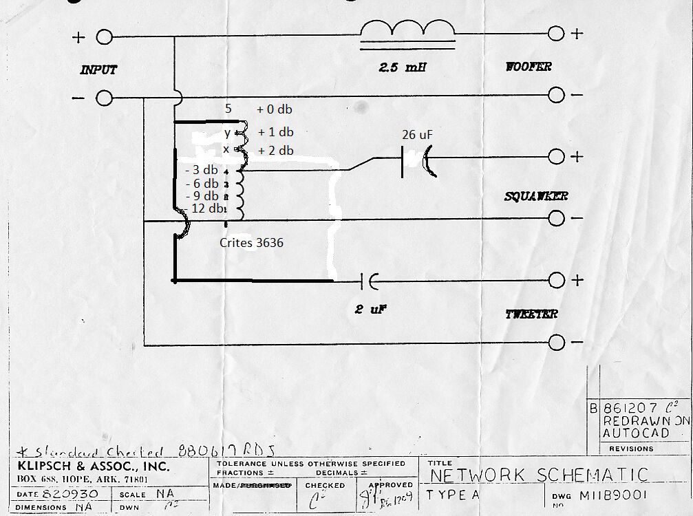
I'm definitely no expert, but... Attached is a schematic of an adjustable Type A that I may build someday. Ignore the 26uf cap on the output. I changed the 3636 to show the taps in a clearer way. In fact, you could put new labels on the 3636, changing... 5 to +0 db y to +1 db x to +2 db 4 to - 3 db 3 to -6 db 2 to -9 db 1 to -12 db The .2mh inductor and 10 ohm resistor should connect to a point on the board, not to the 3636. You then need a wire with a quick disconnect. Solder one end of the the wire to this point, and move the quick disconnect end to +0 db, +1 db, or +2 db taps. Run a wire from the positive side of the K-55 to another point on the board. Again, you then need another wire with a quick disconnect. Solder one end of the the wire to this point, and move the quick disconnect end to -3db, -6db, -9db, or -12db taps. Hopefully, this is a clear way to decrease the voltage to the K-55 in 1 db increments by "adding" the input tap to the output tap. In the attached schematic, input is +0 db, output is -3 db, so the "sum" of the taps = -3 db. I hope that was somewhat clear. Mike
-
Ahh, the fun with passives. After all the work building them, you always wonder if a component here or there would have made an improvement. If you want the tweeter attenuated, you need even more changes. If I were to go to all the effort to build a pair of speakers, I'd go active. Even bi-amped, with a passive between the squawker and the tweeter, will sound great. You can easily play with the woofer to squawker crossing points and voltages. Six or seven years ago, I had Al build me a bi-amp, extreme slope version of his ES5800. He removed the tweeter autoformer and added the squawker autoformer. The picture of the ES5800T on his website is mine. It sounded great, but I wanted the flexibility to go fully passive as well. I built a simple low pass/hi pass filter to put ahead of it, using a 2.5 mH inductor and two 24uF capacitors. Now I have four options...single wire, bi-wire, passive bi-amp, active bi-amp. Mike
-
I would think 2.5mH would be okay. This is an electrical low-pass filter. The natural rolloff of the loaded woofer plays into it as well. I have Khorns. Perhaps someone with Belles could jump in.
-
Nice! Just to be clear, the 48uf capacitor will get you around 400hz to the squawker. For 500 hz, use around 40uf. For 600hz, 33uf. Mike
-
What Klipsch model are you putting it in? Is 400 hz the desired cross?
-
So the stock crossover has no user adjust for the squawker? Well, you can adjust it, but the corner frequency of the stock 13uf capacitor will no longer be around 400 hz. I'd like to keep the 13uf cap rather than going to a 40uf, cap as it keeps the cost down. So are you saying in this scenario, I can't change the squawker level....that it has to be just one particular setting?? Same answer as above, unless you add a resistor across the squawker. If you want the corner frequency of the stock 13uf capacitor to be around 400 hz, the load across taps 0 - 5 has to be twice the impedance of the squawker, or 29 ohms. If you move the output to taps 0 - 3, the impedance in quadrupled (58 ohms). A 14.5 ohm resistor in parallel with the 14.5 ohm squawker gets you to 7.5 ohms. 7.5 times 4 = 29 ohms across taps 0 - 5. So if I change the cap value to 48uf & put the 10ohm resistor in, I can use any tap I want....like in the ALK design?? Yes. & in all these scenarios can I use the 3636 auto former?? Yes.
-
The stock Type AA crossover needs no resistor, as the load on the 13uf high pass capacitor is twice the impedance of the squawker, which is across taps 0 - 4. If you want to keep the 13uf capacitor and use a different output tap number, then you need a specific resistor value across the squawker. The 16 ohm resistor placement in the schematic looks weird, but it will work for output taps 0 - 3. I would use a 14.5 ohm resistor, but that wouldn't change things that much. If you want to choose any output tap number, you need to replace the 13uf capacitor with 48uf (I use two 24uf capacitors in parallel), and put a 10 ohm resistor across taps 0 - 5. You could also add a 35uf capacitor parallel to the 13uf capacitor. The 10 ohm resistor keeps the load somewhat constant regardless of the output taps used. I hope that helps. Mike
-
Swapping the red/black outputs is the solution. Just so you know, this is the solution even if one of the outputs is grounded. When I built Nelson Pass's ACA, the outputs had to be swapped because the single-ended output is inverted. Sorry about missing the picture links. Mike
-
I believe the TPA3255 chip is an inverting amplifier. With the inverting op amps in front, the output phase would have been the same as the input. Can't tell how you connected the input signal to the EVM. Is it underneath...bypassing the op amps? Mike
-
I wonder what the 24uf labeled cap actually measures. It could very well measure 26uf, which is within +- 10% tolerance.
-
Two 70uf caps in parallel to get the 140uf value. Yep...they are pretty big.
-
This link will take you to Klipsch Crossovers. The AK-2 schematic is three-quarters down on the first page. https://community.klipsch.com/index.php?/topic/113804-klipsch-crossovers/
-
I think this is the document describing the issue. I don't remember anyone figuring out how to fix it. If you run differential inputs to the amp and bypass the input op amps, I believe you circumvent the issue. http://www.ti.com/lit/an/slaa719/slaa719.pdf Mike
-
About three-quarters down this page...maybe? https://community.klipsch.com/index.php?/topic/113804-klipsch-crossovers/page/8/ Looks like it was pulled from here... https://audiokarma.org/forums/index.php?threads/crossover-upgrade-on-rf-83s.588494/
-
Another way to look at it... The two rooms are the two capacitor plates. The wall between them is the dielectric. Ideally, the door between the rooms is so small that everyone (the current) will need to go through the hallway (the circuit) to get to the other room (the other plate). In reality, some people do get through the small door (leakage current). Sorry...only door analogy I could come up with.