glens
-
Posts
2337 -
Joined
-
Last visited
Content Type
Forums
Events
Gallery
Everything posted by glens
-
Jeff, are you forgetting that in a double 2nd-order crossover the lows, by the inductors, are delaying the signal by 90 degrees and the highs, by the caps, are advancing the signal by 90 degrees? That's half a wavelength (~8" @ 800 Hz) electrical waveform separation. So to get it right, for a starting point, you'd set the HF voice coil 8" behind the LF voice coil.
-
I've been a fan of JBL since I bought my first pair in the '70s. But you're talking about models that only sell at a rate of a few pairs per year, and largely in Japan, right? Still, I'd like to know just how sonically notable doubling up on the capacitors and biasing one each pair really is.
-
I agree that the notion of preventing current reversal sounds attractive, but only one of any series pair is so affected. The other is still acting the same in that respect as a single non-biased unit would be acting in that circuit location. I'd consider it less than a wash in the case of two equal-value (twice as large) caps. If you used one small-value cap and one ultra-value cap to arrive at the desired pair-value, and biased the huge one I could see maybe deriving some non-current-reversal benefit, but at what cost/performance ratio? In terms of the expansion / contraction, if the cap "breathes" with current flow, I don't see how biasing can do anything about that. It'll just take a further swing in whichever direction than the other. "Nay," says I on this one.
-
Out of circuit (at least one end) for true readings.
-
Depends on the meter. If it measures uF that's only part of what you'd need to know, though if that value is now wrong it's enough to fail the cap. But that value could measure good with the cap still needing replaced. The only all-in-one meters I've seen that can do the whole job are dedicated to capacitors.
-
800 Hz, I believe. 1/16 inch is nominally 5 microseconds of sound travel time in air not terribly far from sea level. That's damn good resolution by ear! One wavelength at 800 Hz is going to be all but 17 inches. 1/16 inch therefore represents ~1.3° phase angle. That's damn good resolution!
-
Squeak, squeak, screech, screech. It could often be temporarily fixed by ejecting the cassette and slapping it against something, both sides, to pack the tape more evenly. That is if the noise resulted from interrupted-and-resumed play and/or FF-or-RW. Done that many a time. Simply pry the shell apart if glued. Of course, you'd need a screwed-together shell available for use... Yeah, 90 minute tapes were the best compromise. It was often possible to juggle the order of the songs on the album(s) so that two programs of somewhat less than 45 minutes each could be derived. Record the longer of the two, then cut the tape splicing the leader back, and record the other side. Minimized blank tape time 'til the direction switched. I once recorded my live UFO album and instead of cutting the tape just faded it out right into the leader and faded it back in on the other side, then filled up the remaining space with other material on the second side. That was ~1979. To this day, when listening to that "album" I expect that same Michael Schenker's solo to fade out, then back in again
-
It may be. Apparently there's a lot of things that I don't know. Logically, it would have to be part of the spec, else how could one espouse following the spec by using something which either falls short of or goes beyond it?
-
(Has anyone checked to see if they've ever posted simultaneously, or is it always in sequence? Hmmm...) That was uncalled for. My apologies.
-
I assumed that was implicit in the spec?
-
Just about any page which shows a wiring diagram should suffice. Two caps in series, with 9 volts fed via 2 resistors, one resistor each end of the downstream (from the amp) cap. The upstream cap remains completely unbiased (unless of course it's reverse-biased via a circuit through any other components, including the voice coil and amplifier output, to achieve the same-enough-though-opposite potential from the battery across the upstream cap - especially unlikely if the second pair of caps in a 3rd order high-pass is also so biased) . Every drawing, including those in the JBL Everest manual (PDF) I found shows the same configuration. I'm surprised the drawings don't call for a (mil-spec wire) lead length factor of some derivative of 57.125 inches...
-
I had to look it up (biasing capacitors in a high-level crossover)... Have to say I'm not enthralled by the notion. You've got to go twice the capacitance, times two, and only one of them gets "class A biased." I even saw mention of higher IM levels as a byproduct (measured, though inexplicably going unnoticed). Sad to say that's one path I'll most likely never explore; thank you very much, but no thanks. My ears are precious, but they're not that golden. I'd sooner "up" my indiscriminate-length speaker leads from 14-ga.
-
I fetched the manual and "thumbed" through it over lunch. It's the combination I'd try based on what I saw. "Small" mains is for when they can't go low.
-
Try "large." And maybe "LFE + main."
-
-
There's an echo in here, in here, in here.
-
Or get a solid-core door for the closet, cut a hole for the woofer, and there you go.
-
An unloaded driver would benefit from neither the "amplification" nor dispersion control of the horn, in this case. How do you surmise that might sound?
-
Jeff, it did not escape my notice in that article that not only did they recommend the speakers, highly so, but that they also used them as reference when judging amplification. Did you read page 3? It tells how they later backed off the recommendation, and use, and why they did so. I'm utterly amazed at the rating of upwards of 100 kHz with that 2" driver. It must have had a focus as tight as that of a lazer beam! Seems to me like a waste of resources, time, and money for something which has no benefit whatsoever to the human aural mechanism. Again, I ask you if the 57-1/8" includes the leads from the final output devices and those internal to (so to speak - would have to include the crossover in that notion even if it weren't physically "inside") the loudspeaker cabinet. If not, why not?
-
The capacitor represents varying impedance to alternating current signals based on frequency. Starts out high impedance at low frequencies and tapers off as the frequency goes up. Eventually the impedance will match that of the high-frequency driver and that will be the "crossover frequency". The capacitor impedance continues to decrease from there and eventually gets out of the way, enough. A single capacitor is a "first order" high-pass filter (crossover), so the driver it's hooked to still carries a fair amount of signal below the crossover frequency. The woofer in this case is being run full-range. It would have a coil of wire (inductor) of a certain size feeding it to attenuate high frequencies in a complementary way to the capacitor on the tweeter. But the woofer in this case loses output as the frequencies go up, both on it's own and, very likely, what's still there is being further blocked by the cone attached to the back of the grill. If you can read a microfarad (uF) value on the capacitor, or find out from literature what it should be, you'd do well to replace it with a new one. The higher the value the lower the frequency the tweeter will reproduce. That ancient unit is more than likely not working correctly any longer, so either the tweeter will be getting too much power or not enough. Definitely worth a few bucks to replace.
-
Through the years I've installed (replaced) many starter relays that look strikingly similar to those units! That was my point. Certainly if they have the required values they should work for the purpose at hand, even if that's what they are.
-
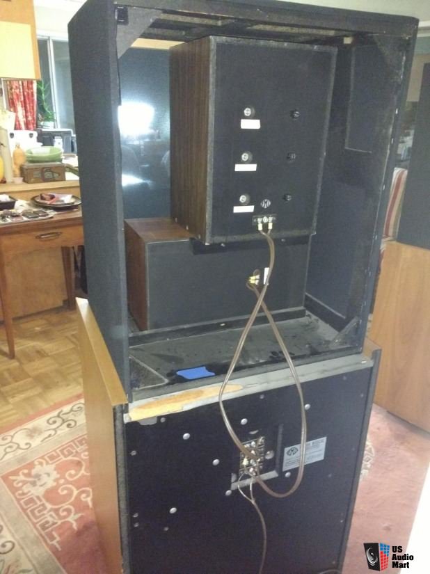
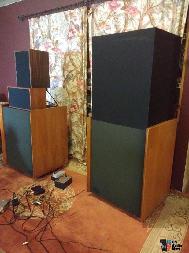
Go read my math, which still refutes the claim, even with my +10 db "stupid loud" exaggeration. Oh, I don't need to re-read your math. I concur with both you and it. My point was merely that I think I've identified the flaw in the other logic. On another note, I did a search for "Fulton Speakers". I'm not suggesting anything like having familiarity with even the vast minority of speaker manufacturers, but this thread introduced me to Fulton for the first time. At any rate, Stereophile has an interesting 3 pages of 4 regarding some Fulton product. The third page is the most fun, but they're short so don't just skip to it. https://www.stereophile.com/standloudspeakers/0973fulton/index.html Another result of the search was an ended sale at US Audio Mart. The link for stereophile will likely be good for some time to come, but I fetched a few images off the Audio Mart page so they will be available from this server for this thread. The speaker "system" is, I believe, mentioned in the stereophile material. In the image of the crossover, I can't help but think the coils look an awful lot like items that could be purchased at AutoZone...

-
I think I can "see" where Jeff is coming from (not that I concur entirely). You can be listening at a level of milliamps average level but a sudden transient would, for the instant, increase the level at a rate that, were it sustained, be amps, yet no so long as to raise the overall average appreciably. And if there weren't a sufficient reservoir of electrons under pressure in the leads (like fuel in the line feeding the Corvette engine), the pressure might fall too far before the transient can be properly delivered, and the speaker would run lean on the peaks. Does that about sum it up, Jeff?
-
Crossover resistors what’s there purpose
glens replied to Ryan0348's topic in Technical/Restorations
Resistors are usually used in a crossover for level matching between drivers and/or impedance shaping. I'm not familiar with those speakers, in either version, so can't offer advice that would be worth a hoot. However, I'd have to guess out loud that you'll want to also go with a "version 2" crossover, assuming the woofers aren't also different between the versions. -
It should be "plug and play" but I'd check the overhang nonetheless.