captainbeefheart
-
Posts
1422 -
Joined
-
Last visited
Content Type
Forums
Events
Gallery
Everything posted by captainbeefheart
-
Cheap Forum Amp by Captainbeefheart
captainbeefheart replied to MEH Synergy's topic in Talkin' Tubes
You officially have me drooling over your 1966 912 coupe. What color are you going to paint the exterior? I always liked either the light ivory or slate grey. Those flat 4 cylinder (616/36) engines are so cool. Are you keeping it all original with the original Solex Carbs? I always envisioned my later years having an old beauty like what you got but as of now it's just not in the cards. A good friend of mine has a few classic cars, 66 GTO, 72 Mustang and a 68 MGB roadster. He is thinking of selling the MG at some point because it's the car he drives the least and his wife has been getting on his case to sell one of the cars since he just picked up his second vintage motorcycle. He is also a vintage hifi nut. The MG is the only car his wife likes to drive as she says the goat and mustang are too big so I think I can convince them to hang onto it for another couple years and hopefully then I can afford a luxury item like that. -
1-5

-
I have 1-5 but not hard covers. She can have them free just pay shipping. I already read them 3 times and plan to get a complete set of hard covers once I get healthy and caught up financially. Reading the books are so much better than the show because of the amount that has changed in the HBO show. Both are good don't get me wrong but I like the books better.
-
Maybe You Have A Juicy Question?
captainbeefheart replied to RealMarkDeneen's topic in 2-Channel Home Audio
Excellent plan so far, especially since you already have the Quasimodo bell ringer to find the correct RC values. I too would just increase transformer leads to go straight to the boards you have then flying wires back to the board. I didn't know you already had those boards, nice job btw. There have been times where traces were in positions where I could cut out the bad spots and scrape the insulation off, then planar mount discrete components from trace to trace essentially just moving the solder pads from one section of the board to another. This obviously doesn't work for vias. I have zero experience with the equipment you are working on but it appears to me the 3 red wires go to the tube socket for tube rectified B+ and the two blue wires are low voltage AC going to the bridge rectifier for DC filaments? There are better options if you aren't opposed to modifications of the circuit. For the longest possible tube service life you may fit a current source to power the filaments instead of a filtered voltage source. The issue with a voltage source is the cold filament in rush current stressing weak spots in the filament. With a current source it will only output say 150mA, when the filament is at a lower resistance I*R will yield lower potential across the filament, as it warms up and resistance increases the current source will increase voltage across the filament until the heater has stabilized. What's even better is you can set it to a tad under the rated current, say 145mA which should yield around 12.2v instead of 12.6v for even longer tube life. With the price of NOS tubes right now, and the fact they will just go up in price as they become more scarce tube life and protection isn't a bad thing. -
To me it's one of those situations where there are so many variables at play that to make an accurate assessment on if the sound will be adequate for your personal tastes or not is to try them. If you don't mind putting in some effort and at worst case scenario you can sell them without it being a big financial burden then I'd say grab em and don't let the opportunity pass you by. When we moved to a ranch my listening room is now half the size as with the previous cape we owned. I just couldn't get my La Scala's to disappear in regard to achieving a phantom auditory scene; e.g. imaging and soundstage. I waited for a very long time for Heresy's to come up for sale in my area and very happy I pulled the trigger when they did. The Heresy just fits the room better where they are better able to perform a magic trick for the ears - a trick where the speakers disappear and a phantom auditory scene comes alive. There was no other way to know for certain if they were going to work well enough for me.
-
No thank you!! Again sorry about the delay, my check was deposited when I was in the hospital.
-
Maybe You Have A Juicy Question?
captainbeefheart replied to RealMarkDeneen's topic in 2-Channel Home Audio
I typically cut the lift traces off the board and where the last good section of trace is and scrape off the trace insulation and then drill a hole if there is no trace on the other side and install a header pin. If there is a trace on the other side of the board I won't drill a hole and utilize a planar type solder joint on the trace. The header pin can then be quickly connected to wires bringing the circuit out to a chassis mount bridge rectifier. Another option is if the only connection from the power transformer secondary is to the rectifier then just de-solder the wires from the power transformer secondary off the board and run them to a chassis mount bridge rectifier. There are other options also if none of these options are viable. I'd also just ditch those caps around the bridge rectifier, they aren't "snubbers". If you want to dampen any rectifier induced LCR ringing the optimal method is an RC network across the secondary winding. Secondary transformer interwinding capacitance and the rectifier diode junction capacitance are in parallel, adding capacitance across the diode only lowers the resonant frequency. The resistance in the RC network across the secondary is what actually does the "snubbing". -
Cheap Forum Amp by Captainbeefheart
captainbeefheart replied to MEH Synergy's topic in Talkin' Tubes
Since both Shakey (Tim) and Westcoastdrums (Chris) asked me to make custom amps the same day I felt it only fair to ship both amps at roughly the same time. As of right now Chris' amp is a little behind Tim's so his will go out 2 weeks after Tim's. I didn't want to show favoritism to one person or the other by building one amp before the other so I'm doing both at the same time. It's a lot of work but I like doing it this way because when I was stuck on one amp, say deciding which tube to use based solely on sonics and not simulation or calculated data I would bring the breadboard to my listening room and listen to it while I switched over to work on the other amp. Basically I could listen to one circuit while working on the other. I don't even start building the actual amplifier until I have the circuit design 100% completed. The reason is because how can I optimize the layout if I don't even know what the circuit will be? Many guys will have a schematic picked out that they found and will build it, then kinda tweak things inside the built amp until they are happy and then it's done. I don't like doing it that way because often times if you try and apply an afterthought you are limited on layout choices since everything is already built in the amp and holes are punched etc...... Tim's amp had the most design time put into it for a couple reasons. The point of a custom amplifier is to make it work best in the application, we know the load is La Scala's but the source being either passive or active would ultimately have a huge impact on the amplifier design. With an active preamp I would be able to decrease the sensitivity of the amp quite a bit since there were gobs of signal swing available at the output to use. That and the fact it has a very low output impedance I could reduce the input impedance of the power amp to reduce noise floor even further. We went from Passive design to active when Tim got his active Benchmark preamp but it was after a few weeks or so that Tim realized his ears did not like the Benchmark and so he had a custom passive preamp made. I needed to go back to the drawing board to increase the input impedance of the amp and also increase the open loop gain. I was breadboarding lots of different circuits to get enough gain, from two cascading gain stages which I didn't really want because an extra gain stage will increase phase shift so keeping the voltage amp to just one stage was ideal. I tried different sharp cutoff pentodes, I tried two triodes wired as cascode (which behaves like a pentode but with better noise figures). My ear settled on the 6SJ7 pentode. That wasn't the hard part either. The tough part is Tim's amp is single ended Class A2. What the heck is A2 you say? It means the power output tube is not AC coupled and the driver circuit can drive the it into positive grid territory where the impedance drops drastically and the grid starts to draw a lot of current. Class A2 is a huge advantage with lower powered amplifiers in that if you do end up running the amp near normal clipping would occur (G1=0v) it won't produce the nasty blocking distortion and bias shift caused by normal A1 operation. Plus you get more output power as a bonus. The crummy part about going this route is just about all the electrical models of tubes out there for simulations do not simulate grid current territory so I needed to do ALL the research on the A2 driver the old fashioned way, on paper and then breadboarding, bench testing and finally listening tests. It takes up a lot of time. What I was trying to sort of compete against was a popular amp called "Bigger Ben" by ampsandsound. That amp with KT88/6550 produces 8 watts with 5% THD and costs nearly $6,000. My amp with the same power tube will do 12 watts with 1% THD and go up to 20 watts when nearing 5% THD, but only costs $1,200. Little bit better specs I think This wasn't the budget amp, Shakey wanted the very best parts and a nice exotic wood chassis with custom BMW paint. The output transformers were a huge chunk of the cost. -
Check your paypal again. Refund should be there.
-
Cheap Forum Amp by Captainbeefheart
captainbeefheart replied to MEH Synergy's topic in Talkin' Tubes
Hey guys I'm okay now. I awoke early one morning in severe pain again and shortness of breath, turned out the hole didn't fix itself and my lung collapsed again worse this time. I went through a procedure where they glued the hole shut so hopefully it won't reoccur ever again. They did originally tell me I had a 1/4 chance of coming back which it did, not fun let me tell you. I charged my phone yesterday and turned it on, I didn't see any texts from Shakey or Chris if they were trying to get a hold of me. I'm also under moderated posts so I don't know when anyone will see this but I figured I would check in here anyway and see what's going on. -
I prefer Trinium, also known as ke by the native Salish people of PXY-887. It's rare and very expensive because the spirits only put so much in the river to be used and get angry if you try and mine more. T'akaya and Xe'ls are very stingy with the trinium.
-
Hard to say really. My La Scala's have the original metal can polymer/foil in oil and what I started doing about 15 years ago was do a sweep of each output of the network, woofer, tweeter, and horn for a total of 3 plots per board. One time I removed the capacitors from one board and measured ESR at frequencies of interest. What I mean is testing the 2uF caps in my AA networks for ESR at 100Hz is not useful information. The 13uF I would test 500Hz through 20kHz. The 2uF caps I would test ESR from 5kHz through 20kHz. Comparing the ESR to what the impedance/reactance of these components are between these frequencies will tell you if losses are acceptable or not. I found the caps to be functioning great and since both networks matched closely and I was happy with the sound I haven't touched them. When sweeping the output of each section of the networks you are looking for a specific transfer function. If this function deviates from the desired intention the networks aren't doing what they were intended to do so one needs to figure out if the capacitors are the culprits and from the reliability of the inductors and transformers it almost always is going to be the capacitors. Basically at point of the intended frequency range where the part is at it's lowest impedance is where the ESR will have the largest losses, since capacitors impedance is lowered as frequency is increased this means that a high ESR will have the greatest losses at the extreme top range of high frequencies; I.e. at 20kHz. Basically I compared to a simulation with as close a parasitic properties as I could add to the models. When you adjust ESR for the capacitors in the simulation it will show the transfer of a network with old caps and high ESR. It will steepen the roll-off slope for the network which is why you'll hear many people report the speakers are brighter after the restoration. Problem is if ESR is a large enough factor in the networks going with an extremely low ESR cap like a modern Polypropylene it may have too low of an insertion loss making the speakers slightly brighter than when they were brand new out of the box. If you don't know what you are doing, or you don't know what you will like; for example an older person with severe hearing loss in the treble range may actually prefer a slightly brighter speaker. But to be safe use the Capacitors from @deang . They use the same dielectric as the originals which is probably the most important factor. If you want to try and get even closer to the original use a polyester and foil type. The ones provided by Dean are metallized film types which won't have a huge impact at all but will still make them have slightly different properties. The dielectric layers with a foil type will be a magnitude size larger vs metallized so they will be larger in size and also the dielectric properties will be more prominent. I have the new JEM caps from Klipsch in my 1975 Heresy's and they sound great. I do plan to switch over to a paper and foil type or polyester and foil and take some measurements between the them but I need to finish other projects first.
-
Depends how hard you were pushing the amp to determine if it's the lack of power being an issue but I doubt it is. The issue is most likely just the design of the 300b amplifier, and no it doesn't have to be a problem with every single ended 300b amplifier, it's just how most are designed. Firstly the majority of 300b amps I see out there have zero negative feedback, especially the single ended ones. It will have too high an output impedance to control tough loads in the bass region. Secondly, if the output transformer isn't designed well enough many of these SET amplifier produce gross amounts of distortion down in the low frequencies. You think 5% is a lot of distortion? That's typical at 1kHz with these open loop amps but go measure down at 35Hz and it's probably over 20% THD. The extra distortion made by the output transformer down in the bass frequencies can be confused sometimes for "more" bass because of the added content that was not there in the original content because it's predominantly nonlinear and so second harmonic. If you have 20% THD at 20Hz then that means for 8v output you'll now have 1.6v of 40Hz that was never there before. This signal that's an octave above the fundamental reinforces it so it can be deceiving. This is why I believe the first problem of high output impedance is the majority of your problem with that 300b amp.
-
I really hope this is sarcasm and meant to be a joke. If so mission accomplished 😂
-
This is always confusing for students. Current changes through a conductor is not the same as electromotive force created from the current change through the conductor but they are related to each other. You need the varying change of currents in order to produce the magnetic field that can be induced into another conductor, like a transformer. I'm not going to get into teaching or explaining this because it's too in depth to cover in one post without sitting here for two hours. Terms to look up and understand. Faraday's law of induction Electric fields and Electromotive force Flemings left/right hand rules In simplest terms Electric fields originate from electric charges and time-varying electric currents like AC current passing through a speaker wire (conductor). It's easy to see there is absolutely zero advantage to cable risers with audio signals passing through speaker wire (straight conductor) once you understand the concepts.
-
What circuit do you plan to use now with this new wood chassis? I can share some of my schematics if you want to try something different. I highly suggest something based on the 4P1L tube because not only do my ears say it's better sounding than a 45 but many others have had similar experiences. If not the 4P1L which can have some not so easy heater requirements for a "simple build" I would recommend a Triode wired 6AV5GA which will end up sounding like a 2A3 but with no hassle of powering the directly heated cathode and they are much less expensive than a 2A3. Then there is the 20 watt SEP amp I'm making for Shakey but it's fixed bias and has a power drive circuit for A2 grid drive operation. Not exactly "simple" but it's not that complicated if you want something more challenging. The only issue with this design is it uses 20db of negative feedback that should be compensated properly, not an easy endeavor for the casual hobbyist amp builder.
-
If you're keeping the amp yourself I see no harm in just leaving them as is. My comment was more for a reference for all builders following the thread. If you end up getting curious (pun intended) about stability with the amount of feedback you have already you don't need anything special. Just shoot some square waves through it and keep increasing capacitance on the load. Start low, like simulating cable capacitance then keep adding more. Use whatever spare values you have on hand. Also if you want to do the bode plot I'll explain my process. It's kinda fun actually.
-
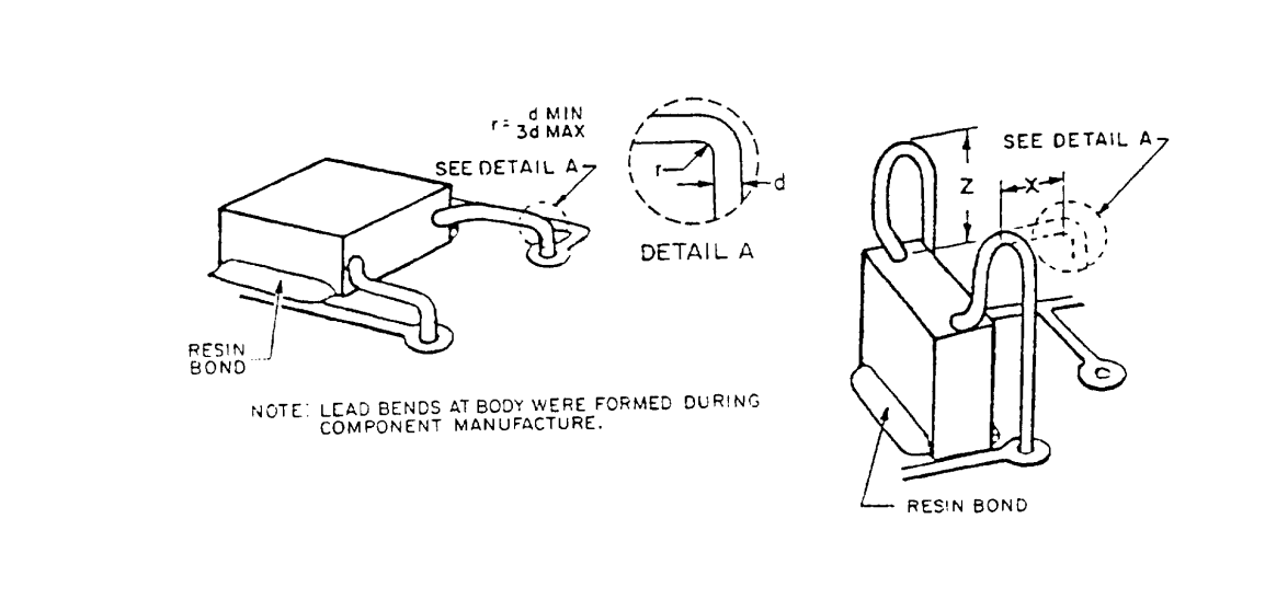
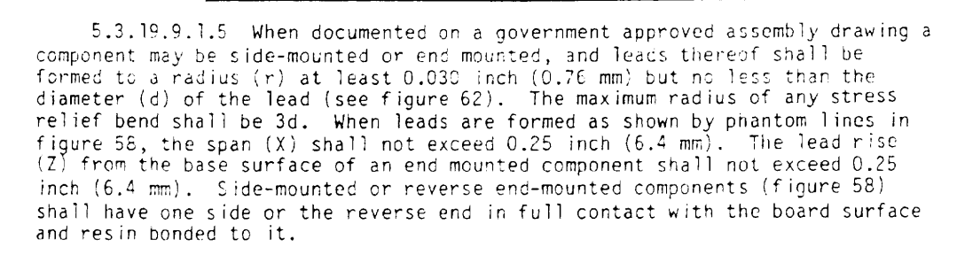
Nick is one of the cleanest builders I have seen on here. I love that sort of stuff. I apparently catch flack for taking too long to build amps but I'm very anal about things. I like the coupling caps going to the tag boards like you did there to keep them from moving around, it's hard to see but a lot of those radial caps don't like the leads bent coming right out of the body. It breaks the seal or "meniscus" and moisture may creep inside. I'll post some images and the explanation for a stress loop except you aren't going down to a board, bring the leads to the tag boards. A little dab of resin/epoxy where the cap meets the chassis helps with end mounted parts. The leads are thick enough to still hold the capacitor stiff against the chassis. Nice rugged layout. I see a lot of builders skip the tag boards and just solder one leg to the tube socket and bring a wire to the other leg, the capacitor kinda just floats around by it's leads and the wire. Not very professional looking in my book. But I'm anal probably because I was programmed to meet a certain standard because if something failed it's would be your butt on the line. That and I always just loved to see rugged MIL spec electronics, it's a science that doubles as a art form almost. Some of those Japanese guys are fantastic builders, you could tumble the amp down a hillside and it would still function perfectly. Just amazing.
-
That's the great thing about feedback, use as little or as much as you like. You have local feedback in your output stage with the distributed loading which is usually the worst offender of distortion so less global feedback makes sense. Since I typically build Pentode operation I have found that 30db or more of feedback gets tough to keep stable with off the shelf EI core output transformers. I found that 20db or slightly higher if i have enough gain is good amount to improve performance but still end up with a healthy phase margin after compensation to where square waves look good even with capacitive loads. Which brings me to my next question. Have you added any reactance to your bench load with the square wave testing? That's how I find if an amp is marginally stable without having to work out it's actual phase and gain margins. In the real world with loudspeakers as a load can push some amps into ringing where on the bench it looks fine. Which is partly why even if I still get decent square waves with the loop closed I continue on to adding compensation networks for the sake of increasing phase margin past the point where I feel confident the amp won't ring with any load it's hooked up to, even electrostatics. Heck I'll even just hook a capacitor up to the amp as the load to see what happens. I'd feel bad if someone hooked my amp up to some ES panels and it at best produced poor sound or worse, damage from the amplifier turned oscillator. I cloned a popular guitar amp load box which contains all passives to emulate a voice coil electrically. I use that sometimes as a "speaker load" test but it's only good for 50 watts. Most of the time I just use my 1800 watt dummy load and hook caps up across it, works just fine. So if your amp keeps stable on a capacitive load then you should be good to go. With 15db of feedback with that circuit you may find it doesn't like the capacitance which is where adding the compensation networks will help. From memory with Edcor transformers a 5-20 circuit with that much feedback will most likely start to misbehave with some reactance. Well, at least for my amps they did but I don't remember testing exactly 15db, more closer to 20db. I have a simulation file of the UL amps I made a while back so all I have to do is go in and pop in the resistor values I was messing with (3.3k-6.8k me thinks) to see how much feedback I got at minimum, which would be a 6.8k resistor. That's with using the 100 ohm resistor for the divider network at the input stage cathode.
-
I might be a little pickier than most people. I didn't like his layouts for certain reasons, like the example of the coupling capacitor with extremely long leads puts stress on the where the leads exit the molding of the capacitor. If he is just going to clone things he may as well follow some MIL spec standards to make his amps better than any random guy in a garage which his looks like, nothing special really. Also the sheer fact he straight copies certain amps that I know for fact will have issues like the WE91A without any modifications is not optimal. His terminology he gets mixed up is a little concerning also, like saying the input requires 300mA to full output 😂 That will give you over 15,000 volts with an input impedance of 50k!! There is no arguing here, you have your opinion and I have mine, we are just sharing our opinions is all. I wouldn't remotely consider him a "bloody good builder", I'll give him he is prolific that's for sure. But of course one can be prolific when you are just whipping amps together without any real thought into a great layout or following any sort of MIL spec for components and soldering. I have seen some all clone builders that aren't engineers but they studied stringent guidelines for their soldering and component layouts and it shows, their underneaths are very rugged and eye candy for us nerds. That I can tip my hat to. I'm not saying you are getting a piece of garbage from Min, but maybe he should slow down on his output and focus more on improving his craft. That's what I like to see, instead of reaching a certain point that's "good enough" and just spitting out amps because you like to move beyond your plateau and improve your craft. Work on better layouts and more rugged construction methods. Study electronics to get a good grasp on problem areas like the positive feedback in older WE amps. I would put him in with average amp builder, nothing special but also nothing garbage either.
-
Maybe I used the wrong cap value? I can't remember what value you (or I) used for the formula as I don't see it in any of the posts. Since you are at 15Hz for resonant frequency now you must have around 220uF in there now? Most of the text books on power supplies for audio amplifiers using LC filters states the resonant frequency should be ideally lower than 10Hz but they might be shooting for flat response down to 20Hz. Of course the high pass filters for the coupling stages could be set high enough to not cause issues with the resonant frequency. Same goes for if the output transformer or anything else limiting low frequencies etc... If you are using 20kHz square waves that is like testing for 200kHz, I usually start at 1kHz and work my way up to 20kHz. There were some instances where 10kHz was worse than 20kHz, I'm thinking it depends where the resonant frequency is at in the output transformer? That was odd which is why I just test at different frequencies in case there is an anomaly. The amp looks great underneath and it sounds like it's working great for you. How much feedback are you using currently?
-
I can hear it now. PWK from beyond the grave guiding Roy through the Ojiou board to authentic parts selection😂
-
Exactly. If quoting someone but for whatever reason a word gets changed to another word that means the exact same thing then it's odd and inaccurate but at least conveys the original quotes intention/message. I think Schu might be integrating his own thoughts into the quote, like the contour of the horn will most likely have an effect, distortion could be one effect and hence "color" the sound.
-
Contours to coloration, these are not synonyms.
-
I'm sure Mr. Delgado chooses components for his work just like any other engineer. The application dictates parts selection and the engineer puts the puzzle pieces together. For example, reading through a datasheet for a specific 3 terminal LDO voltage regulator there will most likely be a graph somewhere that shows stability vs ESR for the output capacitor. The engineer will know that ESR is the main property that needs to be chosen carefully. I think for capacitors in networks Mr. Delgado has said as long as the output of a filter meets his targeted transfer function then it's the correct capacitor. So in that particular application he is looking for a very specific transfer function from the filter and whatever parts get him where he needs to be then they are the correct ones for the application. Of course I am paraphrasing what he said from memory but that's the gist.