Al Klappenberger Posted March 21, 2005 Share Posted March 21, 2005 Shawn, Something doesn't look right with that curve! I have a hard time beliving the response is that bad! Look at the smoother curve. Even it is 1 dB down at 20KHz. It should be virtually flat into a load resistor. I could believe it was the curves for a SET amp, but not a high quality amp of any brand! Al K. Quote Link to comment Share on other sites More sharing options...
BS Button Posted March 21, 2005 Share Posted March 21, 2005 Paper in oil caps? Is that the cheap looking pc of garbage on most of these networks. Looks like it's got a metal bridge over it? Could somebody post a picture for us nimrods? Old with cost? vs. new with cost and benefits of the new? BS Quote Link to comment Share on other sites More sharing options...
Dflip Posted March 21, 2005 Share Posted March 21, 2005 colterphoto1 What capacitors are in your B3 networks for your Cornwall II's? The Cornwall II schematic is located in this post. I am just not sure which version this is, B2 or B3. I can't read schematics, but it appears to have a couple of inductors, 3.0, 3.0 and .16 mHy and one big *** capacitor, 68, and a 3 and two 1.5 uF capacitors. http://forums.klipsch.com/idealbb/view.asp?topicID=60291&forumID=66&catID=19&search=1&searchstring=&sessionID={9545211D-3440-4FFA-99D5-1D332DC61D6B} The B networks are simple by comparison, a 2.4 or 2.5 mHy solid wire inductor and a 2.0 and 4.0 capacitor. A lot cheaper to build and they do sound quite good. Don Quote Link to comment Share on other sites More sharing options...
Dflip Posted March 21, 2005 Share Posted March 21, 2005 Original caps in a Cornwall Type B network. They would be the oval shaped cans, one 2.0 uF and the other 4.0 uF. The inductor is to the right and the T2A autoformer is to the left. Check some of Dean's posts for what a revised version looks like with Auricap polypropylene or Jensen PIO's. Quote Link to comment Share on other sites More sharing options...
dodger Posted March 21, 2005 Share Posted March 21, 2005 For what is now a number of 6, Appreciation is given to Bob Crites for the Courtesy of answering a question posed in writing THREE (3) times. Though it may have appeared to be a no brainer, I did agree to post it. For me in Marketing any product, the answering of questions is important. To others it very well could be the difference as to whom they would use. dodger Quote Link to comment Share on other sites More sharing options...
colterphoto1 Posted March 21, 2005 Share Posted March 21, 2005 Okay, I'm looking at my B3 network. It has three transformer-looking thingies, those are the 'autoformers' that represent the coil portion of the low-pass networks, right? One says t2a and it has 6 labeled 'taps' on it numbered 0-5. I guess this is what you guys mean when you say 'change the tap from x to z'? There are two black plastic boxes about 1" square x 1/2 wide that I think are the capacitors with the values 5uF and 2 uF, there is a big oj can about 1 1/2 dia x 4" long that says 70uF, is that another cap? It's wired straight away from the input pos to the woofer neg terminal. Then there is another little round thingie that looks like it might be another choke. Shouldn't there be some resistors in this to cut the output of the tweet and mid to match the efficiency of the woofer? All I know is that this is entirely different from my B networks on the 1963's. Looks like I'll be taking the full semester course on Crossovers this summer. Michael Quote Link to comment Share on other sites More sharing options...
dodger Posted March 21, 2005 Share Posted March 21, 2005 Michael: Didn't you post a photo of it or was that your Cornwall? dodger Quote Link to comment Share on other sites More sharing options...
colterphoto1 Posted March 21, 2005 Share Posted March 21, 2005 edit sorry Quote Link to comment Share on other sites More sharing options...
colterphoto1 Posted March 21, 2005 Share Posted March 21, 2005 edit Quote Link to comment Share on other sites More sharing options...
BEC Posted March 21, 2005 Share Posted March 21, 2005 ---------------- On 3/21/2005 7:04:34 PM colterphoto1 wrote: Okay, I'm looking at my B3 network. It has three transformer-looking thingies, those are the 'autoformers' that represent the coil portion of the low-pass networks, right? One says t2a and it has 6 labeled 'taps' on it numbered 0-5. I guess this is what you guys mean when you say 'change the tap from x to z'? There are two black plastic boxes about 1" square x 1/2 wide that I think are the capacitors with the values 5uF and 2 uF, there is a big oj can about 1 1/2 dia x 4" long that says 70uF, is that another cap? It's wired straight away from the input pos to the woofer neg terminal. Then there is another little round thingie that looks like it might be another choke. Shouldn't there be some resistors in this to cut the output of the tweet and mid to match the efficiency of the woofer? All I know is that this is entirely different from my B networks on the 1963's. Looks like I'll be taking the full semester course on Crossovers this summer. Michael ---------------- Michael, The device labeled T2A is the autotransformer. It attenuates the squawker and tweeter to match the woofer. The 5 uF device is a capacitor the feeds the midrange frequencies to the autotransformer. The 2 uF device is a capacitor that routes the highs to the tweeter, The largest of the "transformer looking things" is the woofer inductor. Sends the lows to the woofer. The 70 uF device keeps highs out of the woofer. The other "transformer looking" device is a 2.5 mH inductor. (My, that is a weird hook-up. I guess it works.) The "little round thingie" is a 125 uH inductor that helps keep lows out of the tweeter. Ok, that is a pretty simplistic explanation and there is more too it than that. Bob Crites Quote Link to comment Share on other sites More sharing options...
Dflip Posted March 21, 2005 Share Posted March 21, 2005 Bob, you worded that so that the less knowledgable could follow the parts by looking at the inside of their Cornwalls. You do it so much better than I could. Don Quote Link to comment Share on other sites More sharing options...
Marvel Posted March 21, 2005 Share Posted March 21, 2005 Michael, What are the file names you used when posting the pics? Marvel Quote Link to comment Share on other sites More sharing options...
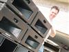
colterphoto1 Posted March 21, 2005 Share Posted March 21, 2005 There, that's better, okay, this is a photo of one of the B networks from my 1963 Cornwalls (most recent acquisition) My these are certainly different. Looks to me like the B3 is more complex, possibly 2nd order (12db slope) in a few places???? Michael Bob, thanks for the explanation, now I've just got to get used to tracing from diagrams onto the board so I know what's what. This is interesting! So if any of these xovers don't have the 'can' oil and paper capacitors, there is little to go wrong, is that correct? How about that bump at 9 kHz that the K55 has? Will I need to deal with that as well through that 'trap' circuit or implement a lo pass on the sqwaker? (am I getting any better at the terms guys?) The autoformers are just a coil, right, nothing to drift out of spec? Quote Link to comment Share on other sites More sharing options...
BEC Posted March 21, 2005 Share Posted March 21, 2005 Michael, That type B in the picture is definately an oldie. From the days of hand wound inductors. Not even sure what the second inductor on that one is for. Most type B networks just have one inductor and one autotransformer along with 2 capacitors. The caps,wire and connections are the only thing on the networks that would certainly be subject to effects of aging. If the other stuff is effected by aging, it is likely to be over a longer period of time than for the items mentioned earlier. Bob Quote Link to comment Share on other sites More sharing options...
Deang Posted March 21, 2005 Share Posted March 21, 2005 That rogue inductor is in series with the squawker. Quote Link to comment Share on other sites More sharing options...
BEC Posted March 21, 2005 Share Posted March 21, 2005 We should name that one the B minus 1 perhaps. Bob Quote Link to comment Share on other sites More sharing options...
BEC Posted March 21, 2005 Share Posted March 21, 2005 Michael, I forgot earlier to address your question on the (supposed) 9 khz glitch. I have spent a lot of time searching for that glitch since I so often found it mentioned on this forum. I have been unable to find anything really significant at 9 khz in my testing of the K-55V drivers. Perhaps the reason is in this recent post by Tom Brennan. "The fella tht developed the P Trap (a very experienced old horny and friend of PWK) reports that about 20% of the K-55 drivers he tested had the 9khz flare. One can't assume that one needs a P Trap but it's a good thing to try if your certain older Klipsch sounds harsh and fierce." Perhaps I just haven't run into one of that 20 percent so far. Bob Crites Quote Link to comment Share on other sites More sharing options...
sfogg Posted March 21, 2005 Share Posted March 21, 2005 Bob, "Perhaps I just haven't run into one of that 20 percent so far." Could be. I certainly saw it in the K55Vs in my '76 LaScala's. Shawn Quote Link to comment Share on other sites More sharing options...
colterphoto1 Posted March 22, 2005 Share Posted March 22, 2005 Dean sez.. 'That rogue inductor is in series with the squawker.' So if my new learning is correct Dean, that would indicate a 12 db slope on the high pass side of the squawker, yes? That would be a good thing in terms of driver protection. I should think that this should be required. Bob, so then does my B-1 pictured here need to have it's caps changed out? I take it those are the two cans bolted to the board. Or could these components be tested individually to see if they're still in spec? For some reason, I would like to keep the 63's as stock as possible. Looks like the 85's B3 (for center channel) is up to snuff. It's the one described earlier- since it's got so many parts it must also be 12 db slopes. Probably the ones in need of most care might be the B?'s from my 1974's, which are most likely the B2's. Those speakers have metal horns on K55's and are somewhat harsh. Re the K55 9 kHz bump, could this be tamed with either the 'trap' or a proper lowpass filter (same thing) as an addition to the xover board? I think I've read that one K55 has solder terminals, one has spring types, only one of which has the 'bump' perhaps that corresponds to the 20% figure? Sorry so many ??, but I think I'm starting to get a handle on this. It's tough owning all three genres of Corns when there seems to be infinite permututations of this famous cabinet. I go sleepy sleep now... Michael "This new learning amazes me, tell me again Sir Bedevere, how sheep's bladders may be used to prevent earthquakes" King Arthur- Monty Python Search for the Holy Grail. Quote Link to comment Share on other sites More sharing options...
dodger Posted March 22, 2005 Share Posted March 22, 2005 edited Quote Link to comment Share on other sites More sharing options...

Recommended Posts
Join the conversation
You can post now and register later. If you have an account, sign in now to post with your account.
Note: Your post will require moderator approval before it will be visible.