DirtyErnie
-
Posts
387 -
Joined
-
Last visited
Content Type
Forums
Events
Gallery
Everything posted by DirtyErnie
-
What size/thread for spikes on a set of CF2s? Not super impressed with the lower frequencies and want to try spiking them to the subfloor. I will say, the lower extension is great, but not much authority. Smallish room, maybe 13x15, 800 square foot first floor with three bedrooms, bathroom, kitchen.
-
There are many ways to skin a cat. Klipsch, being a large producer, is likely to aim for the one that costs less. Quite a complex crossover posted for the Econowave, CF2 is much simpler.
-
You're right about what a constant directivity Horn does, but all the (manufacturers) literature and theory I've seen about the beasts says they need a 6db/octave power increase above about 5KHz to keep a flat frequency response across their wider directivity. I'm pretty sure (granted, it's from about an hour playing with Xsim) that the first 1.75uf cap sets that 6db/octave slope, as it's -3db break point with an 8-ohm driver is around 12khz. If that's the case, one could theoretically be able to take a -3db attenuation from the whole Tweeter Horn by moving that point a half octave higher, to around 18KHz.
-
Doesn't that first 1.75uf cap set a 6db slope to compensate for the constant-directivity of the horn? I see the same set-up on my CF2's, same horn I think. Would it be possible to both decrease the volume a bit (3db) and extend the treble by moving that cap's break-point up a half octave?
-
 Your DC resistance measurement is going through the crossover coils into two parallel 8 ohm woofers, so that looks about right. The tweeter is 8 ohms, above the crossover, and the woofers are 4 ohms below the crossover. It's a trick to keep the levels similar; tweeter is high efficiency horn, woofers get +3dB by having two of them, and another +3 dB by having half the impedance/drawing twice as much power. Would be fun to see the impedance curve through a frequency sweep.
 -
Finding a good receiver for Klipsch speakers
DirtyErnie replied to Fallenangel's topic in Home Theater
With the RF-260's and a 5.x speaker set-up, I'd vote for finding a 7.x receiver that can bi-amp, and then bi-amp the RF-260's. -
You'd be surprised how much cleaner your CF3's (any speaker, really, especially ported ones) will sound if you can cross them to 50Hz+ and run all the lower stuff through the sub. Getting all that wasted cone motion & port delay/slop out of your sound makes a huge difference.
-
Power, Clarity, and Emotion at Mike D's in Maine
DirtyErnie replied to Delicious2's topic in 2-Channel Home Audio
Naw, man! It's "Horn if you're honky!" -
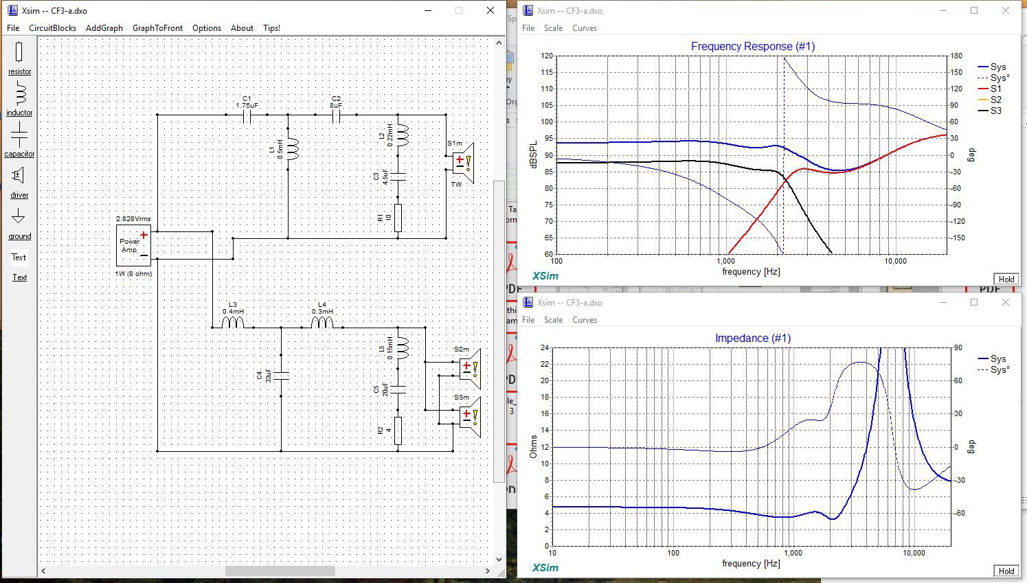
Downloaded Xsim and started to play around with the inductor values I didn't have with the earlier schematic I posted. Screenshot below is what I came up with, and should be fairly close for a 2,200 Hz 2-way crossover. The RLC filter inductors were based on the assumption of a .7 Q factor. If that's valid: Low-pass RLC knocks out three decibles centered around 1,850Hz, useful to take out some of the 'beaming' effect of pushing a pair of 8" drivers separated by a 7" high horn up to 2,200Hz. I have a feeling these speakers would be decent candidates for a 2.5 way treatment, but I'm not gonna be messing with that while The Toddler is in charge around this house. High-pass RLC is centered around 5,050 Hz, likely to tame some effect in the horn/driver combo. Hi-pass has a 1st order slope up to about 11KHz, which seems about right for a C/D conical/tractrix horn. Again, this is my educated guessing at what's actually in there, unless someone comes up with an official schematic, or pulls one apart and measures the values. Again, I'm on Toddler Time, so... The first low-pass inductor could be larger, on the order of .6mH or so to also roll-down some of the beaming issues in the midrange. It is significantly bigger than any other inductor on the board. Assumed driver efficiencies: Horn: 106dB 8" Woofers: 89dB Figured those values *might* get us into a fairly close ballpark, so don't get all snippy if the output looks weird; this was an ASSUMPTION. Yeah, it could all be crap, but I had fun while the kid was napping. Thanks. P.S.: I'd really like to multi-amp these with an active crossover and filter setup, but that's just not in the cards for the near future...

-
Bi-Wiring & multiple impedance OPT
DirtyErnie replied to DirtyErnie's topic in Technical/Restorations
Yes, but above the pass-band for the 4 ohm circuit is an 8-ohm circuit taking the load, third order, so two series capacitors and a coil shunted to ground. Where one circuit starts to phase out and change impedance, the other circuit is phasing in and dropping into it's pass-band. Knowing what we know of KG/Epic/KLH + series impedance traces, it seems the WTW, TMWW arrangements are nominally 8 ohms, but love to drop down into the sub-4-ohm range lower in the frequency bands; right where they're going to draw the most power. Solid state amps, good ones anyways, don't have a problem with supplying the current. Tube amps are a little more picky, especially small pentodes like the EL84s in question. I'm definitely going to try this when I get the time. Will do one speaker at a time and a lot of listening. Should be fun. -
Bi-Wiring & multiple impedance OPT
DirtyErnie replied to DirtyErnie's topic in Technical/Restorations
Read both of the forum post links, neither seems like the situation at hand. Since each tap would be feeding a band limiting filter (crossover), only the pass-band frequencies would be able to get out of any given transformer tap. Third order crossovers would keep the overlap down to a reasonably small amount. Current/power won't be going where it shouldn't go. How the Scott is set up for feeding speakers: there are two identical strips, one for each channel. Each channel has: two 0-ohm/neutral taps, and one each of 4, 8, and 16 ohms. Each tap is a screw terminal, suitable for bare wire or a fork lug. Ultimately, this is a variation of Bi-Wiring, isn't it? -
Bi-Wiring & multiple impedance OPT
DirtyErnie replied to DirtyErnie's topic in Technical/Restorations
Question to be answered: if these speakers were designed for solid state drive, the woofers are getting +3dB for being x2, and +3dB for pulling 2x power from a solid state supply. Might bet on Glens thought of tweeters going +3dB... -
Bi-Wiring & multiple impedance OPT
DirtyErnie replied to DirtyErnie's topic in Technical/Restorations
Not quite sure what that has to do with the discussion at hand. -
Bi-Wiring & multiple impedance OPT
DirtyErnie replied to DirtyErnie's topic in Technical/Restorations
That's a question in my mine, too: where does this wiring scheme put the speaker load on the plate curves? It's likely the low impedance of the woofers was too 'vertical' of an operating line to begin with and they weren't getting powered quite right off the amp (was running from the 8-ohm tap). Setting that Load Line to it's correct position could only help, and with a tube amp that means more left-right (voltage) swing before the load line blows out the top of the plate curve (runs out of current). I'd think re-aligning the load lines for woofers and tweeters could only improve operating conditions for the power tubes and force less correction through the NFB loop. Fun mental exercise, this. Too bad the KGs are in my basement lab, not exactly a 'critical listening' environment. That doesn't matter with solid state, but we're not talking about sand. -
Bi-Wiring & multiple impedance OPT
DirtyErnie replied to DirtyErnie's topic in Technical/Restorations
Glens, the KGs were good, but I don't think they were top-shelf. Anywho, might try it some day. -
Had a thought about this: I have a Scott 222C, it has 4,8,16-ohm outputs and two 0-ohm returns/commons. (Edit: per channel!) I also have a pair of KG2.5 and a pair of CF2 speakers, both have WTW arrangement, 8 ohm tweets, and a pair of 8 ohm woofers in parallel. Thinking of splitting the inputs on the x-over boards, direct wiring the hi-pass filter to the 8 ohm OPT tap and the low-pass filters to the 4-ohm tap. Then each frequency band would be getting fed by the correct tap and reflecting appropriate loads back to the power amp. Any good reasons to stop right there and come back to sanity?
-
I'll also echo the tag board/construction paper method. I've done this with my CF2's and an old Kustom 4x12 cabinet when I was playing bass and gigging a bunch.
-
Well, disregard everything I just posted... One speaker was wired backwards. Effenheimer! Nice to finally have some bass, though.
-
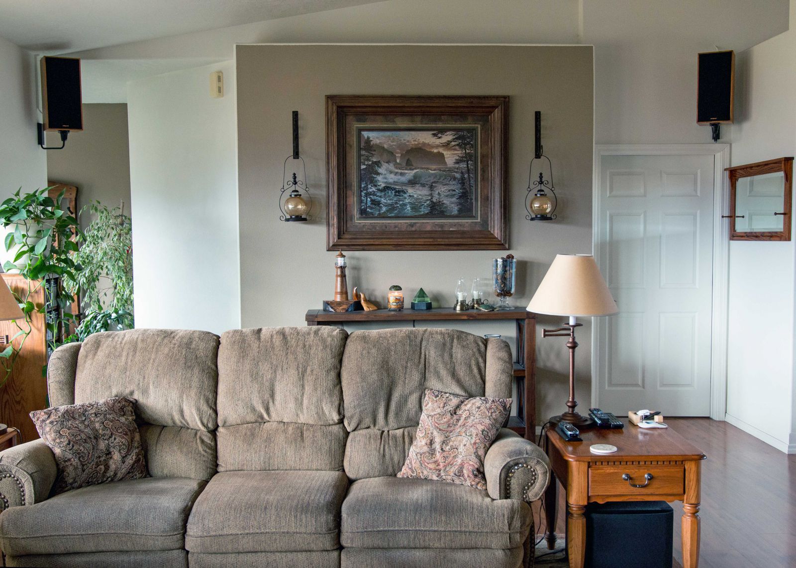
That's probably not far off from where I have them turned right now. Maybe I'll post a picture some day. 😉 I'm loving how these things throw sound through the whole house without getting that loud. The horns could probably use an L-pad, maybe with some HF EQ to balance everything.
-
I tried the CF2's straight-ahead, and it wasn't great, weird kind of hot-spot in the middle, and a bit of a 'head in a vise' hot-spot right down the middle. Then tried them toed-in, pointing directly at the MLP, the hot-spot in the middle sounded better, but it was even more of a 'head in a vise' affair. Now I have them toed-in pretty severely, so that the horn directivity on both speakers covers both the main and side sofas in the (small) living room I have. Things are much more even-handed now. Sound got even better after letting the cheap sony HTIB receiver run it's calibration sweeps with the supplied microphone. Yeah, it's not strictly hi-fi, but it's working pretty well on my budget (and with small children, I'm definitely not putting the vacuum tubes back on display )
-
 did those Omni mounts line up with the holes in the bottom of the 2.5's, or was there drilling involved?
 -
Not really that, more of the modern YouTube type. Flat-Earther and all that stuff. Basically, one of those guys that thought he knew something but was missing a little bit of basic physics. There's a lot of garbage out there, and a little bit that isn't garbage and will piss a fella right off.... Anyways, back to tubes.
-
What would you do with these 12"ers?
DirtyErnie replied to DirtyErnie's topic in Technical/Restorations
Edgar, that's about what I was thinking it would be. -
What would you do with these 12"ers?
DirtyErnie replied to DirtyErnie's topic in Technical/Restorations
Let's riff on 'open baffle' vs 'infinite baffle' for a minute. any real appreciable difference? Maybe it's my perspective, when I think 'Open baffle' I'm thinking of a board with a speaker in the middle of it, usually reserved for Lowthers or somesuch. "Infinite Baffle" makes me think of what JohnA posted. -
What would you do with these 12"ers?
DirtyErnie replied to DirtyErnie's topic in Technical/Restorations
Seismic Audio Earthshaker. Allegedly a stronger motor version of their Richter model. Infinite baffle into the basement has crossed my mind. (Attic it's right out, there's a good 2' of fiberglass and blow-in insulation up there). Speakers in the cream Fender clone are Carvin PS12B, some kind of Eminence re-branded. Beta, I think.